
MicroMAS-2
MicroMAS-2a, short for Micro-sized Microwave Atmospheric Satellite, is a radiometer-equipped CubeSat mission flying as a follow-up to the original MicroMAS that successfully demonstrated the satellite core systems but was not able to gather data with its radiometer due to a transmitter failure.
The project continues under leadership of MIT/LL (Massachusetts Institute of Technology/Lincoln Laboratory), MIT/SSL (Space Systems Laboratory) and the University of Massachusetts at Amherst with funding from the United States Air Force and the National Oceanic and Atmospheric Administration.
MicroMAS-1 was launched aboard the second operational Cygnus spacecraft resupplying the International Space Station in 2014 and was deployed from the orbiting laboratory on March 4, 2015 on a planned 100-day demonstration mission. The primary objective of the mission was to demonstrate the satellite platform systems and the functionality of the radiometer payload and its moving parts with actual data collection classed as a bonus objective.
MicroMAS-1 hosted a nine-channel radiometer only sensitive in the 118 GHz band to demonstrate a CubeSat could deliver radiometric data useful for scientific applications as well as operational weather forecasting. All key spacecraft subsystems could be demonstrated by the mission but actual radiometer data could not be collected due to a radio transmitter failure.
The success of the MicroMAS-1 mission was carried into development of a more advanced version with a four-band, 12-channel radiometer observing in the 90, 118, 183 and 206 GHz bands typically identified as the most crucial for temperature and humidity sounding. The initial MicroMAS mission also fed into the MiRaTA technology demonstration that combines a miniature radiometer with GPS occultation measurements to demonstrate a novel method for instrument calibration that may become the future of operational space-based atmospheric sensing.
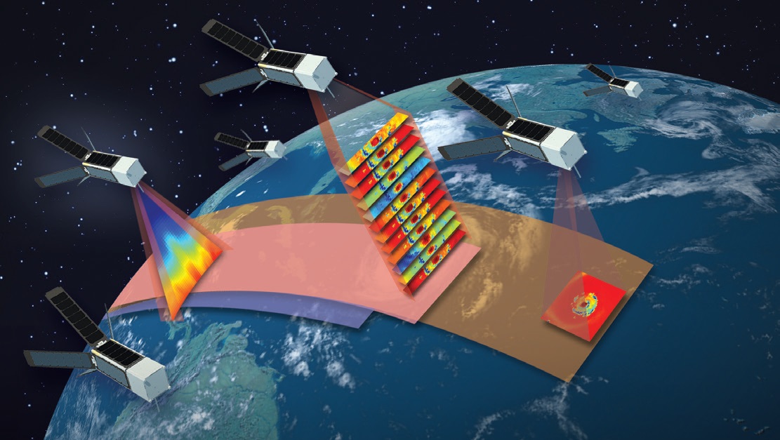
If successful, the MicroMAS-2 missions will build the foundation for a 12-satellite, three-plane constellation known as TROPICS-CubeSats deployed into 600-Kilometer orbits at a 30-degree inclination to deliver high-revisit coverage of the tropical regions where high-refresh-rate data is of critical importance when following fast-progressing phenomena like hurricanes. The full constellation would be able to deliver data at a 30-minute revisit.
MicroMAS-2 carries a multi-band passive microwave radiometer to demonstrate miniaturized radiometer technology in space for application in ultra-compact spacecraft systems such as a high-performance multi-band sounder for future weather satellites.
The low-cost, mission-flexible MicroMAS bus could find use in the development of a constellation of radiometer satellites that could provide near-continuous coverage. A continuous coverage would be desired as the current coverage using high-cost platforms has a longer revisit time leading to gaps in data during which rapid changes in storms can be missed.
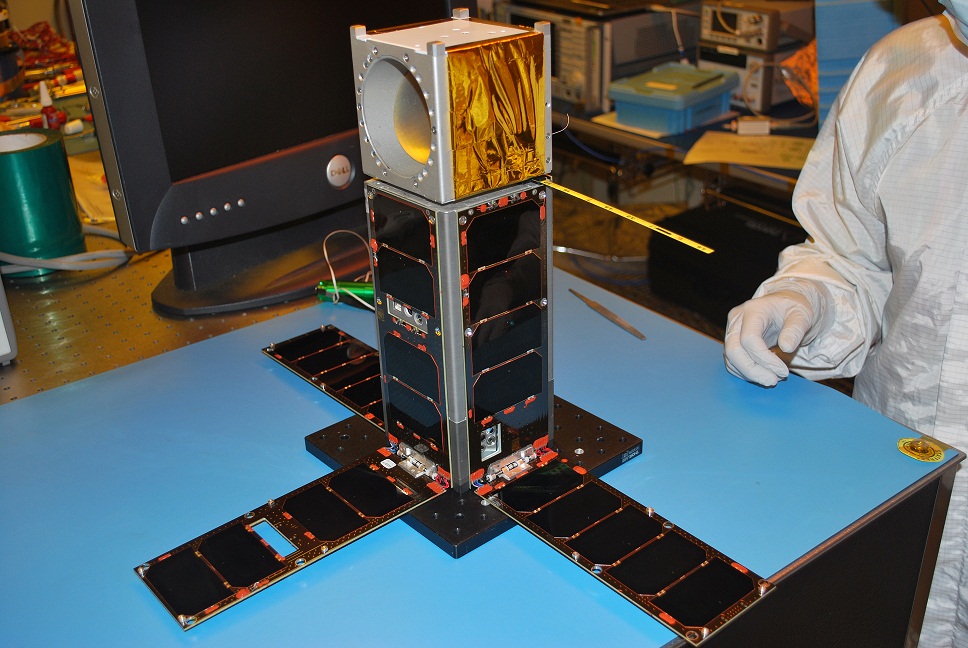
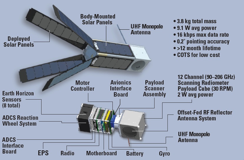
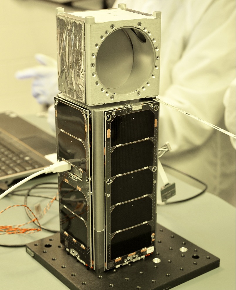
The MicroMAS-2 CubeSat consists of a two-unit platform section and a one-unit payload section connected the the platform via a spinner assembly that rotates the payload at 30rpm. The 3.8-Kilogram satellite measures 10 by 10 by 34 centimeters in size and employs three-axis stabilization, deployable solar panels and data management to fulfill its task of autonomously collecting radiometry data that is transmitted to Earth for processing and analysis for use in weather models.
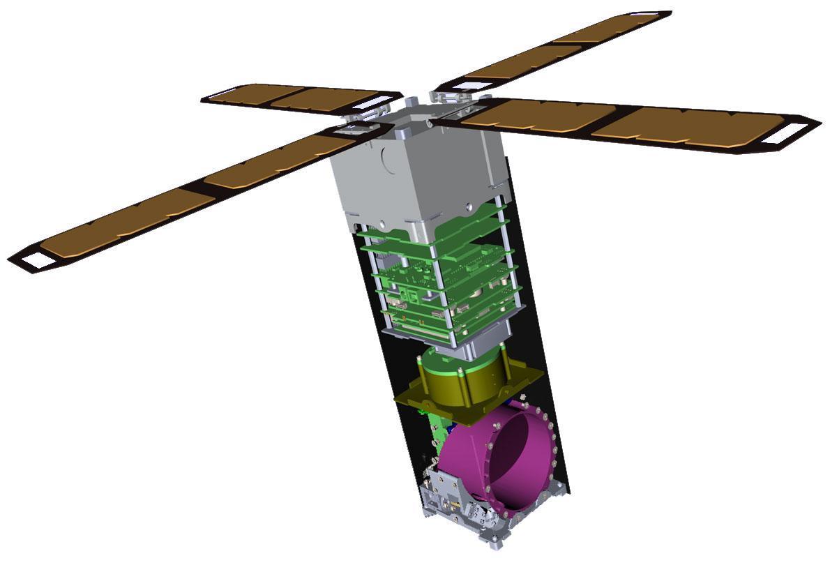
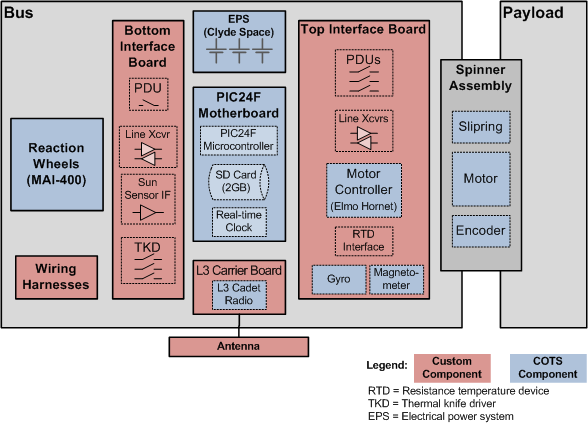
The satellite bus consists of an 0.5-Unit external Attitude Determination and Control Subsystem coupled with a 1.5U skeleton chassis provided by Pumpkin Inc., widely used in CubeSat applications. The 2U bus is attached to the payload via the spinner assembly that includes a 6mm gap for spinner clearance.
The internal components of the satellite platform are arranged in the following order: Attitude Determination & Control Unit, ADCS interface board, S-Band comm board, battery, electrical power system, satellite controller, payload interface unit, magnetometer, encoder head, Scanner Assembly motor.
The satellite uses mostly passive thermal control featuring thermal tape that is attached to individual components and provides a thermal interface to the exterior of the satellite where heat is radiated into space using the highly emissive tape for a total heat emission of up to 20 Watts. Active thermal control in the form of heaters is used for thermally critical systems such as batteries and microcontrollers.

The attitude control system of the satellite consists of reaction wheels that are used to stabilize the 2U satellite bus and keep it in an Earth-pointing attitude with one panel facing Earth. The ADCS is tasked with eliminating any transients and disturbances from the spinning system and keep the satellite bus pointed correctly while the payload spins. Attitude determination is accomplished using an Inertial Measurement Unit, a three-axis magnetometer, Earth horizon sensors and sun sensors.
In its de-tumble mode, the satellite uses three torque-rods and its IMU & magnetometer to reduce rates on all three axes to less than one degree per second. This leaves the spacecraft in an arbitrary attitude from which it will recover by switching to Slew Mode using the reaction wheels and the TRIAD navigation method that compares the magnetometer and sun vectors using a model of Earth’s magnetic field and an astronomical almanac for sun position comparisons. In slew mode, the torque rods are used for momentum dumps of the reaction wheels. The Earth horizon sensors provide a final verification of the correct attitude for scientific measurements.
Once in the correct science attitude, the satellite switches to stabilization mode where the TRIAD method is again used for attitude determination using the magnetometer, but switching from the sun sensors to the IR Earth horizon sensors to provide the second vector in addition to the magnetometer output. In this mode, the X-axis reaction wheel will spin at about 8000rpm to compensate for the rotation of the spinning payload. This compensation will be sufficient to allow the satellite to be pointed with an accuracy of 30 arcmin when in science mode.
Electrical power is provided by four 3U double sided solar panels that are deployed in a dart-type arrangement at an angle of 120° to the satellite structure. An additional 2U solar panel is installed on the zenith-facing side of the satellite platform. The satellite uses Ultra Triple Junction solar cells to generate an average power of 9.1 Watts. Power is stored in 30 Watt-hour lithium polymer batteries and an EPS card conditions the power buses at 3.3, 5 and 12 Volts and provides bus protection.
The satellite motherboard is a standard CubeSat board provided by Pumpkin using a PIC24 microcontroller that serves as flight computer that runs on Pumpkin’s Salvo Real Time Operating System. The satellite uses CubeSat-Kit interfaces for the reaction wheels, communication system and mass memory while the PCB is used for the attitude sensors, motor controller and payload. Payload Data is stored in an SD card.
Communications are accomplished with a half-duplex L-3 Communications Cadet UHF Nanosatellite radio. Operating at a frequency of 450MHz for uplink, the system achieves a data rate of 9.6kbit/s with GFSK modulation and 16kbit/s with FEC. Downlink uses the 468MHz UHF frequency for low data volumes and an S-Band transmitter to reach 3Mbit/s for payload data downlink.
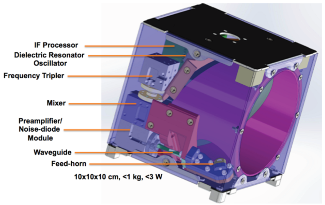
The payload of Micro-MAS is a total-power passive microwave radiometer/scatterometer that is similar to deployed instruments, but uses miniaturized systems to fit within the 1U form factor in terms of mass, size and power/data availability.
A microwave radiometer observes the radiance of the atmosphere at microwave wavelengths that are detected by an antenna which uses support electronics to detect and amplify the signals of given frequency bands. The detected power level for each frequency band is used to generate temperature and moisture profiles through the various regions of the atmosphere. Elements present in the atmosphere have different absorption spectra, allowing radiometers to observe different atmospheric constituents.

The radiometer uses a parabolic reflector that focuses a conical scalar feed horn toward the satellite footprint on Earth. The reflector system has been designed with a worst-case beam efficiency of 95° and a beam width of 3°. The antenna has a 9cm aperture and uses a 3dB beam to create a nadir ground resolution of 20 Kilometers across a 2,500-Kilometer ground swath which can be compared with high-cost satellite radiometers. Of each antenna rotation, 155 degrees around nadir are used for atmospheric scanning while the rest of the rotation is available for calibration measurements and data processing.
The major improvement from MicroMAS that only sounded one frequency band, MicroMAS-2 covers 12 channels in four microwave bands at 89 GHz for water vapor measurement & correction, 118 GHz for temperature, pressure & precipitation, 183 GHz for humidity and precipitation and 207 GHz as another water vapor band.

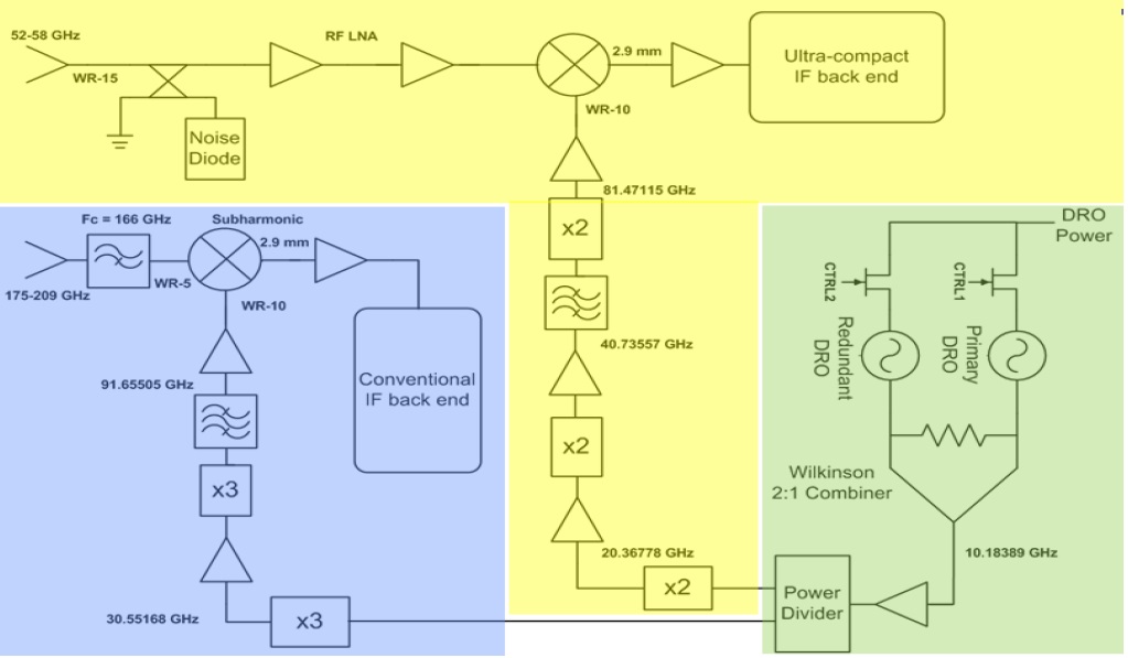
The instrument uses highly miniaturized technology – the tripler, mixer/preamplifier and RF electronics weigh just about 100 grams and are integrated as a single unit. The Local Oscillator of the mixer is produced by a tripler housed in a separate block operating at 90GHz. The overall RF gain exceeds 40dB while the IF gain is over 30dB with a front-end noise of under 5dB. Channelization, detection and conversion is accomplished in a single unit, the Integrated Frequency Processor.
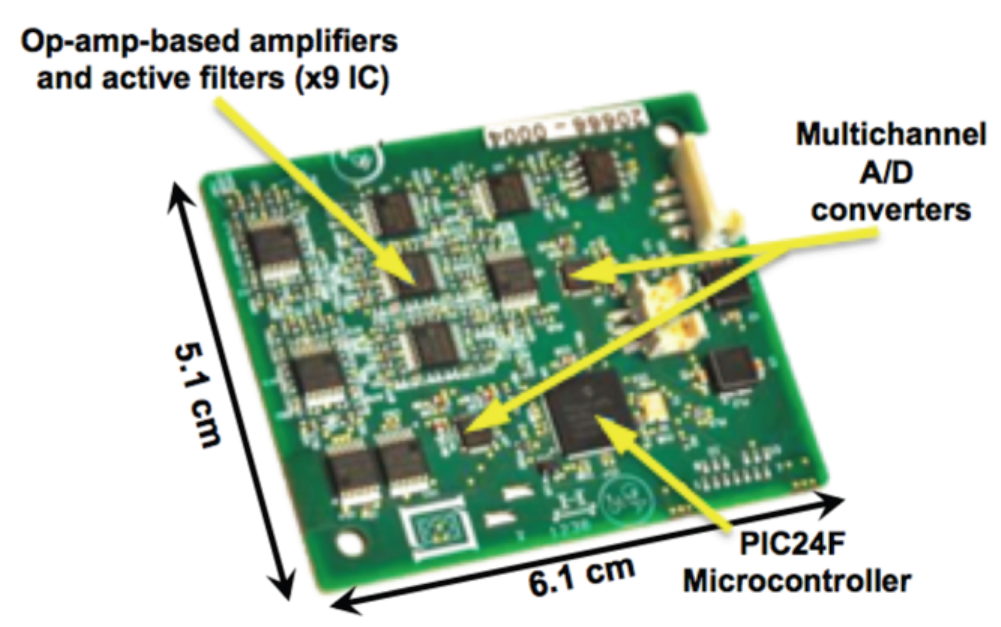
Each channel has its own amplifier and filter system that feeds amplified and filtered signals to multichannel analog-to-digital converters that generate the digital data output of the instrument that is stored in the spacecraft memory ahead of being downlinked.
The payload includes a Payload Interface Module that connects it to the data system of the satellite while a Voltage Regulator Module enables the system to be integrated into different satellite buses for flexible mission architectures. Average payload power is 3 Watts.
The observation at these frequencies yield a temperature and precipitation profile from ground level up to an altitude of 20 Kilometers at a sufficient quality for weather forecast models.
The overall objective of the Micro-MAS satellite is to demonstrate the feasibility of operating meteorological instruments on a CubeSat scale to create a constellation of many spacecraft to minimize revisit time and increase the real-time tracking and short-term forecasting capabilities with special focus on severe weather. A constant data stream can be used for now-casting and short-term forecasting of storm initiation, evolution and decay and help in the warning process.
