PicSat Satellite Overview
PicSat is a three-unit Astronomy CubeSat hosting an interferometric imaging system to measure Exoplanet transits via continuous observations without atmospheric disturbances. The satellite employs single-mode fiber filtering and single pixel avalanche photodiodes for high-accuracy photometry and also serves as a pathfinder for future interferometric missions.
Miniaturizing interferometric instruments to fit the constraints imposed by the CubeSat form factor (volume, power, cost) would be of great benefit for Exoplanet research as it offers the opportunity of launching a large number of low-cost spacecraft that could be tasked with continuous measurements of various targets of interest.
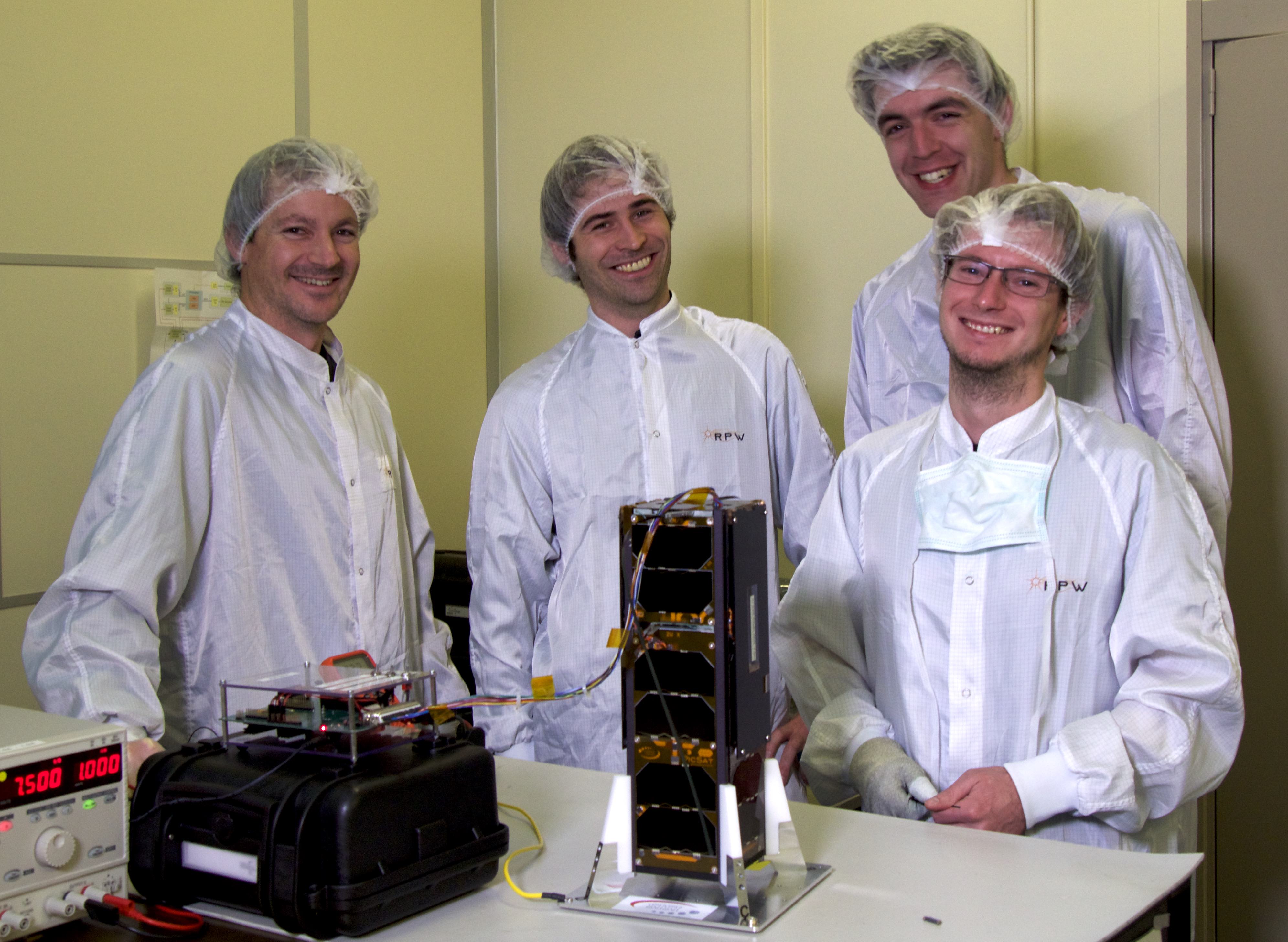
The PicSat mission is conducted by he High Angular Resolution Astronomy group at LESIA (Laboratoire d’Etudes Spatiales et d’Instrumentation en Astrophysique), Observatoire de Paris, and three university partners. In addition to its pathfinder role for future missions, PicSat has the specific mission objective of observing the transit of the planet Beta Pictoris b across its host star.
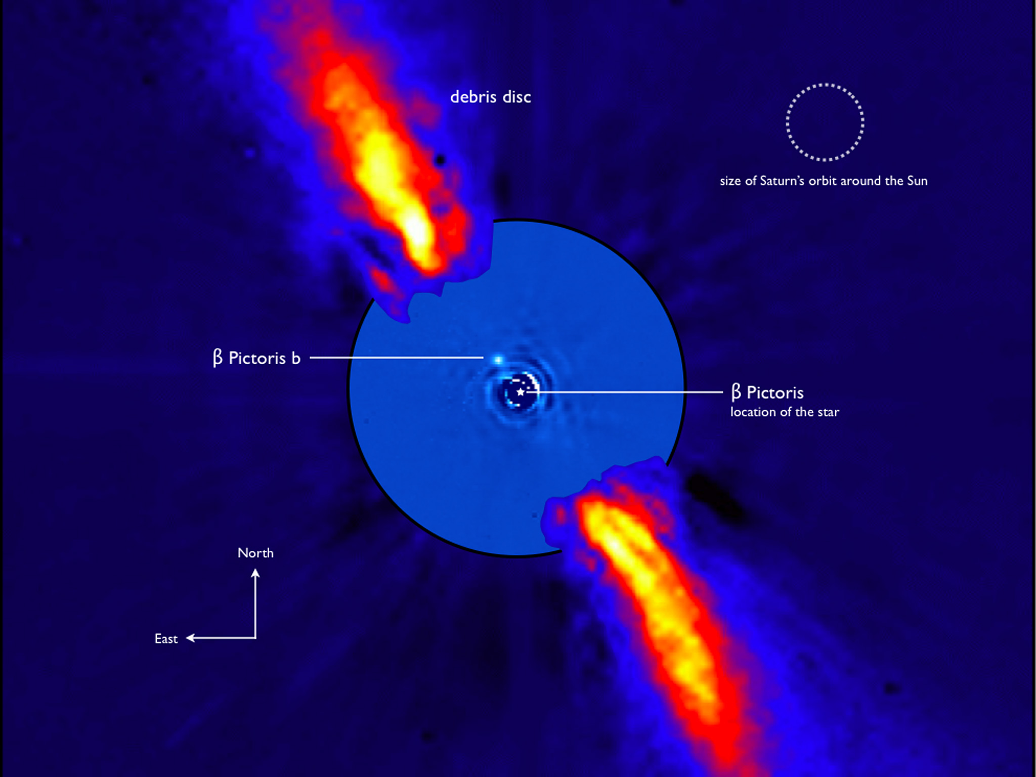
Beta Pictoris b was discovered in 2008 by Lagrange et al. through re-reduction of direct imaging data collected in 2003 by the Very Large Telescope in Chile; its discovery was largely owed to the development of modern image processing tools that revealed the faint point source. The planet is of particular interest since it is the closest orbiting planet to its star ever imaged. It is seven times more massive than Jupiter and, with a rotation period of 8.1 hours, is the fastest-spinning planet known – faster than Jupiter’s ten-hour rotation period.
Measurements taken between 2003 and 2015 allowed the planet’s orbital parameters to be refined and indicate Beta Pictoris b passes in front of its host star – consistent with a 1981 transit-like event that generated important photometric data. Based on the timing of the November 1981 event and the refined orbital parameters, scientists predicted the next transit between July 2017 and March 2018.

The chance of observing a transit of a young planet over an astronomically close and bright star was deemed an extremely valuable scientific opportunity that prompted development of the PicSat mission. Observing the transit requires continuous photometric monitoring of Beta Pictoris which is only possible with a space observatory, avoiding atmospheric disturbances and the day-night cycle.
PicSat was originally manifested on the PSLV C38 mission in June 2017 to be in orbit and operating at the opening of the transit window, but the spacecraft was not ready in time and was pushed to the next PSLV cluster mission that had been set for November, still with plenty of time in the window. However, the PSLV C40 mission ended up being delayed nearly two months due to the failure of PSLV C39 that suffered a problem with its payload fairing and grounded PSLV while the mishap was investigated.
Launching in January 2018 may very well mean PicSat will miss its opportunity to study the transit but the mission is still of value for its technical demonstration aspect and the instrument can add valuable scientific knowledge by characterizing the debris disk around β Pic to learn more about its structure and the dust tails of exo-comets.
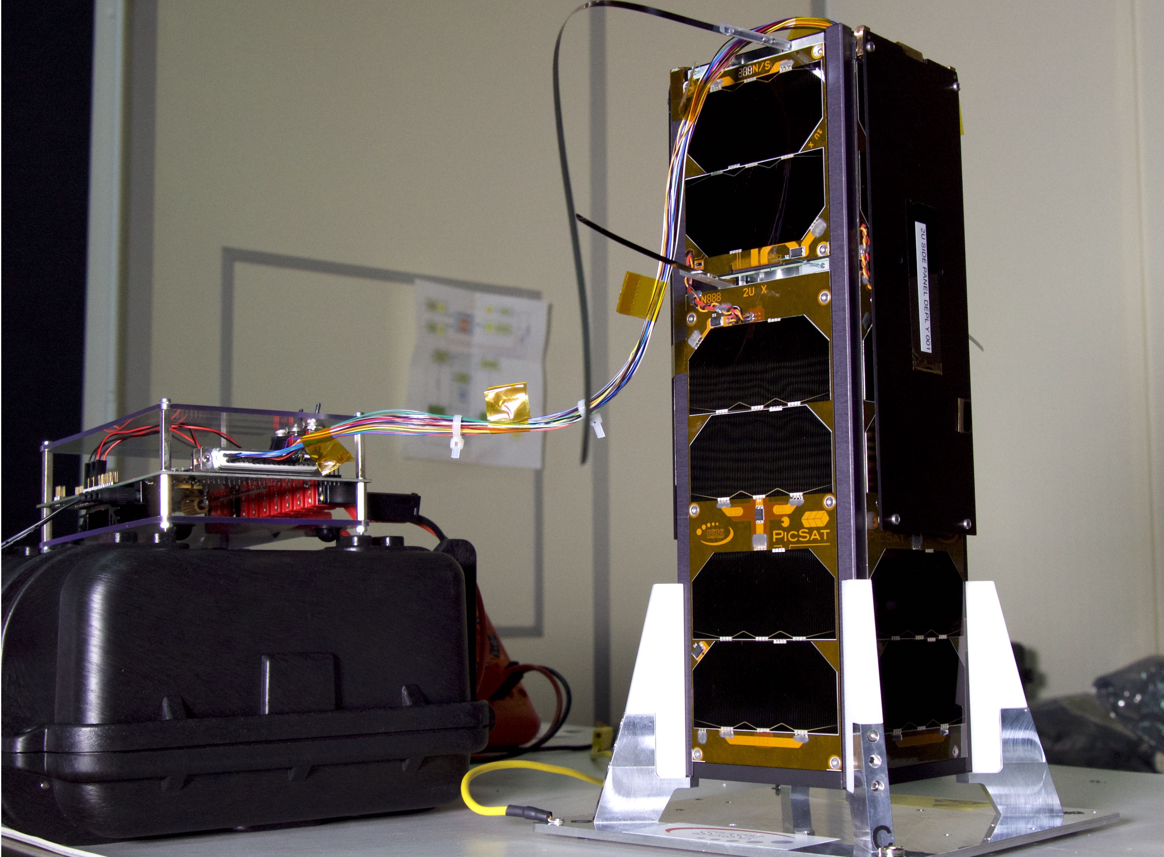
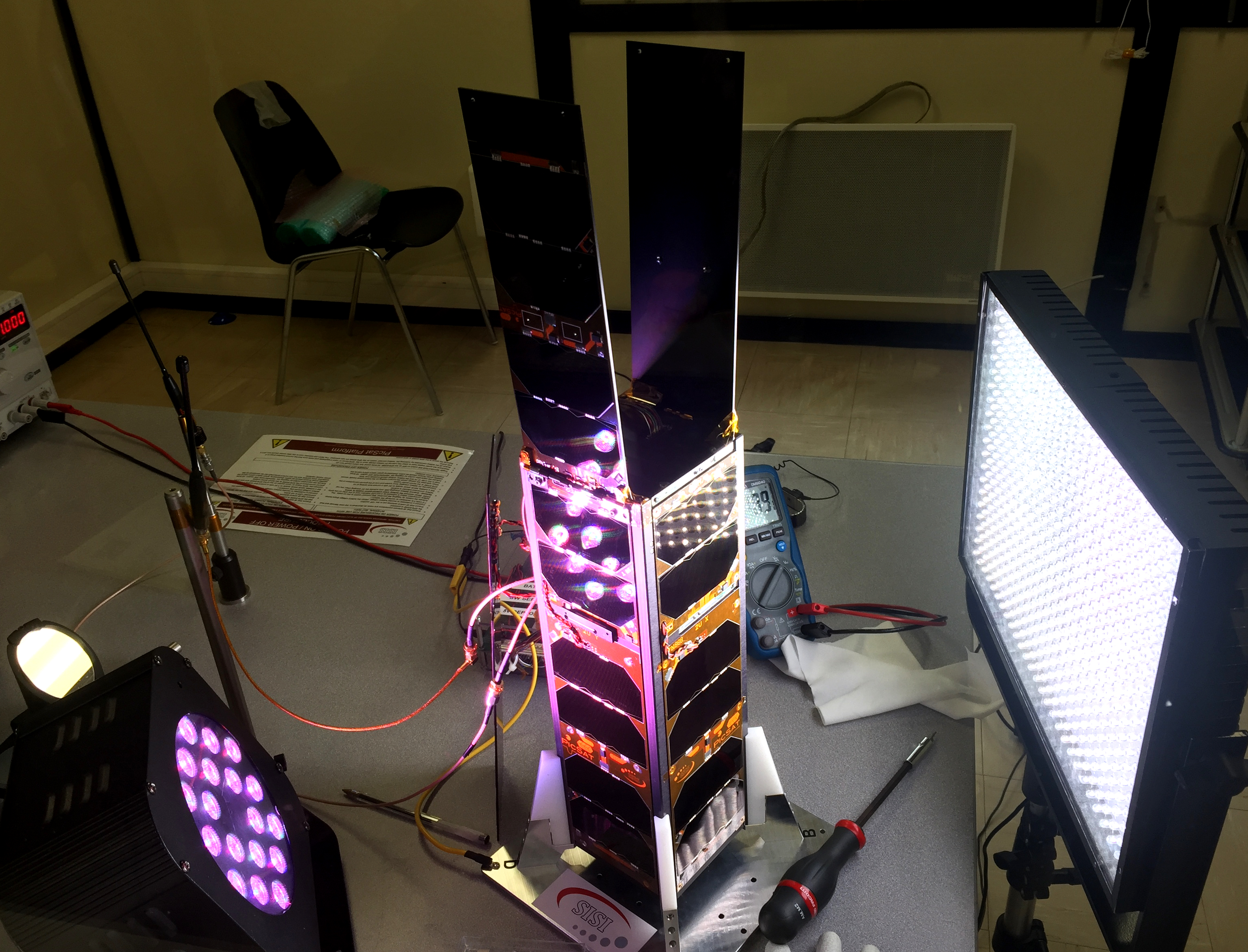
PicSat, 30 x 10 x 10 centimeters in size with a mass of 4 Kilograms, complies with the 3U CubeSat Form Factor and employs a standard platform. The platform, bus and attitude control system have all been subcontracted by the PicSat collaboration as in-house development focused solely on the instrument. Particular attention was paid to the selection of the Attitude Determination and Control System since precise and jitter-free pointing are critical for an interferometric imaging instrument.
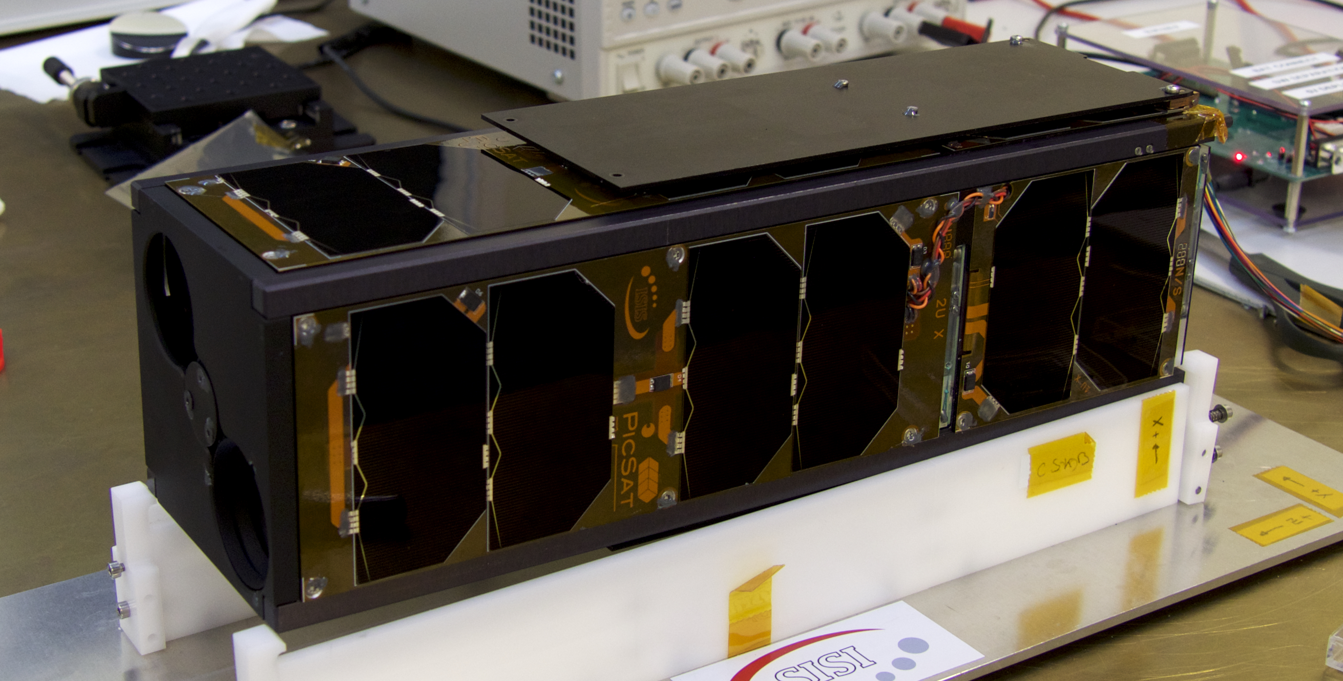
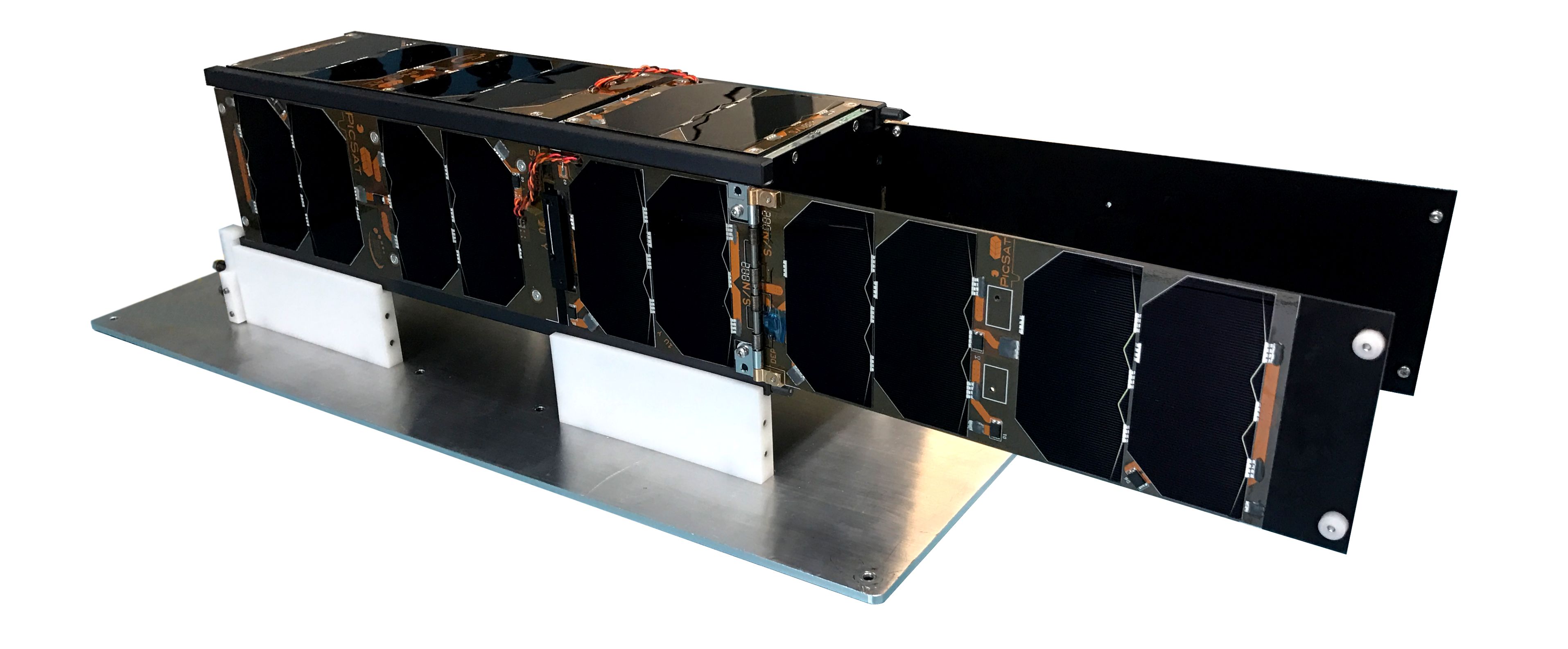
The satellite structure, communication, command and data handling and power system all use designs provided by ISIS (Innovative Solutions In Space). PicSat’s structure was slightly adapted from the standard 3U package to accommodate the telescopic payload. The Electrical Power System comprises a GomSpace P31U management system and a GomSpace BP4 battery pack with a capacity of 37.4 Watt-hours. Power is generated by a total of 32 solar cells installed around the satellite body and on two deployable panels to deliver the required orbit-average power for continuous operation of the instrument.
PicSat uses the iDACS-100 Integrated Attitude Determination and Control System provided by Berlin Space Technologies and Hyperion Technologies, Delft as an integrated unit consolidating all attitude determination and control functions.

iDACS-100 is a self-contained attitude control solution, consisting of a star tracker, MEMS sensors, three reaction wheels and magnetic torquers and a star tracker unit plus a computing unit capable of attitude determination and actuation of the wheels and torquers for three-axis control as commanded by the main flight computer. iDACS-100 is 95 by 90 by 32 millimeters in size and weighs 350 grams, making it one of the smallest full-functional ADCS packages currently in operation.
For iDACS-100, Berlin Space Technologies provides overall management and system design as well as the structure, assembly and testing of the unit while Hyperion is responsible for the electronics design and production of the wheels and torquers. iDACS-100 requires 0.5 to 1.8 Watts of electrical power and communicates with the CubeSat platform via an RS485 serial link and I2C circuitry.
The primary sensors of iDACS are the Micro-Electro Mechanical System (MEMS) suite that measures body rates and acceleration and is employed during the initial de-tumble to enable the Star Tracker to acquire an attitude solution. A magnetometer within the MEMS suite provides information on the current magnetic environment for actuation of the magnetic torquers.
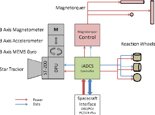
The ST-200 star tracker captures imagery of the star-filled sky that are processed by an onboard algorithm with a star catalog to calculate the precise three-axis orientation of the satellite with a typical attitude knowledge of 30 arcsec. Auxiliary sensors used by iDACS are a series of Fine Sun Sensors that provide knowledge on the solar vector for safe mode attitude control. A GPS receiver connected via I²C provides time references a precise position measurements.
The actuators of the iDACS system are three RW200 reaction wheels with a torque of 0.087mNm and a momentum capacity of 1.5 mNms, enabling attitude slew rates of over 1.5 degrees per second. The achieved pointing accuracy will be better than one degree, permitting iDACS to be used on Earth observation missions. Three magnetic torquers are available for use in attitude control during spacecraft safe mode and for regular momentum dumps from the reaction wheels
At the center of the satellite is an onboard computer in charge of actuation of all satellite systems and handling of systems telemetry data as well as science data from the payload. It uses an ARM 9 processor with an additional pluggable daughter board supporting the payload. A pair of 32 GB SD Cards serve as the primary memory for data collected by the instrument. The PicSat flight software was developed by LESIA as a key investment for future missions, based on a RTOS (Real Time Operating System) containing a number of management modes to handle the satellite’s core functions and process data from the payload.
The Communications System uses an ISIS TR x VU transceiver, transmitting in UHF at 435 MHz and receiving in VHF at 145 MHz. An additional ham radio transponder on the satellite will be activated when the craft’s power state allows.
The single payload of the PicSat spacecraft is known as PFP – PicSat Fibered Photometer, an interferometric instrument with the sensitivity needed to observe exoplanet transits, study exo-comet transits that have so far only been detected through transit spectrometry, study the structure of a debris disk around a young star, and demonstrate light injection into a single mode fiber that could open up possibilities for future instrument designs.
PFP fits into a single CubeSat Unit (10 x 10 x 10 centimeters) and weighs 1.3 Kilograms, ideally suited for the CubeSat Form Factor while offering high-precision photometry.
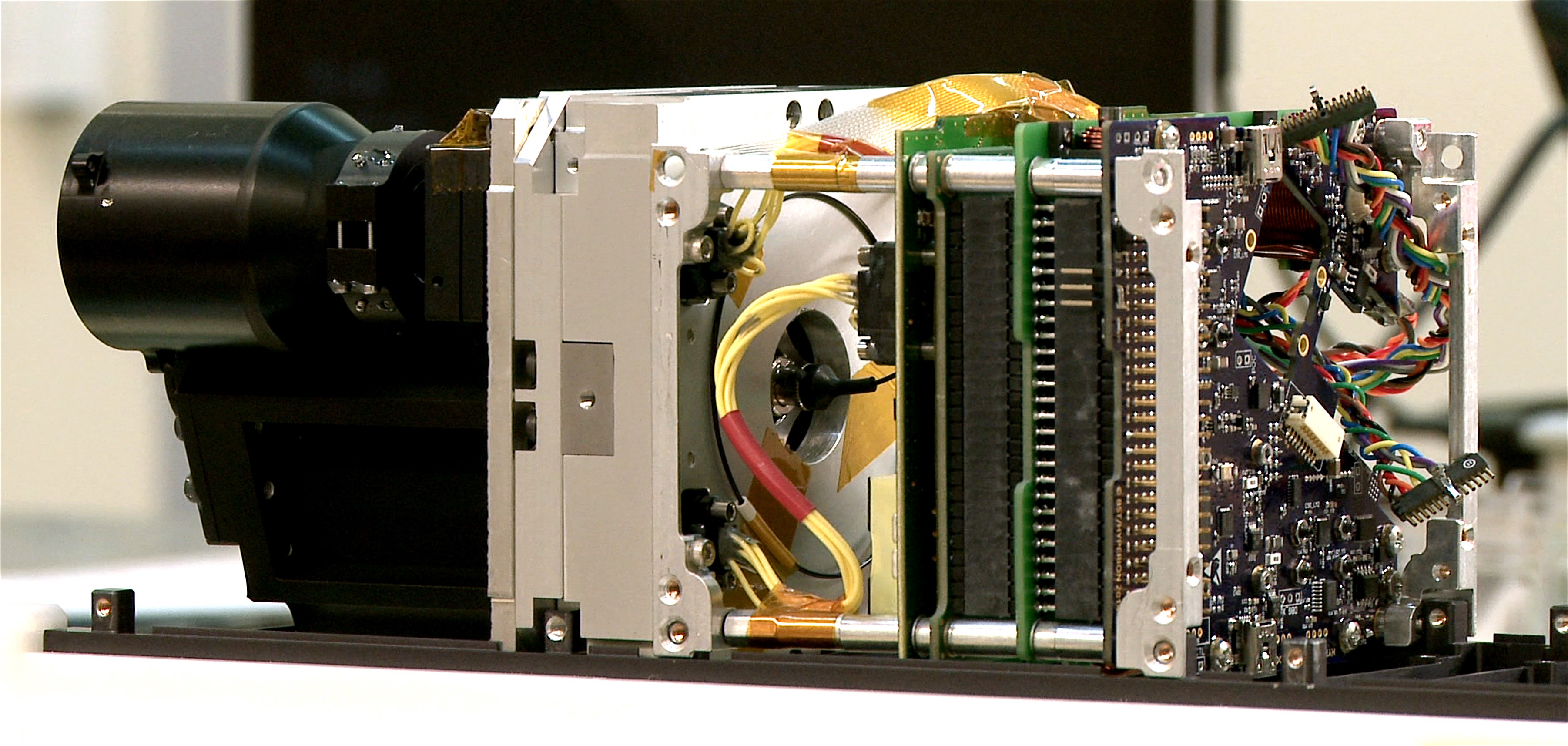
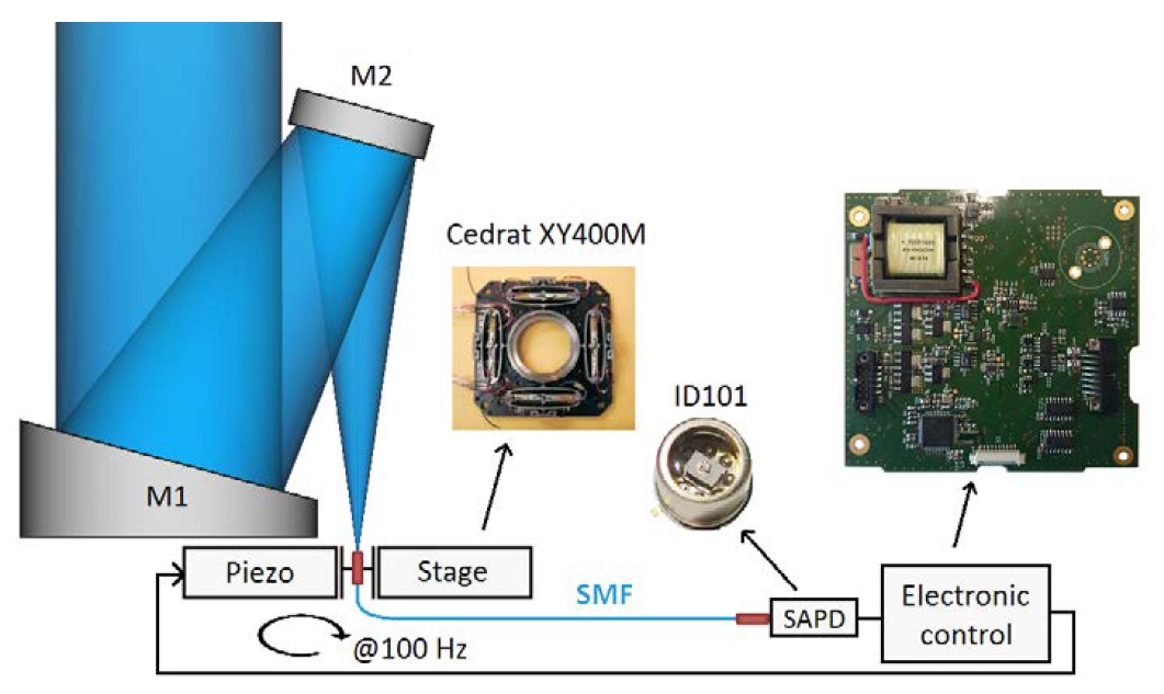
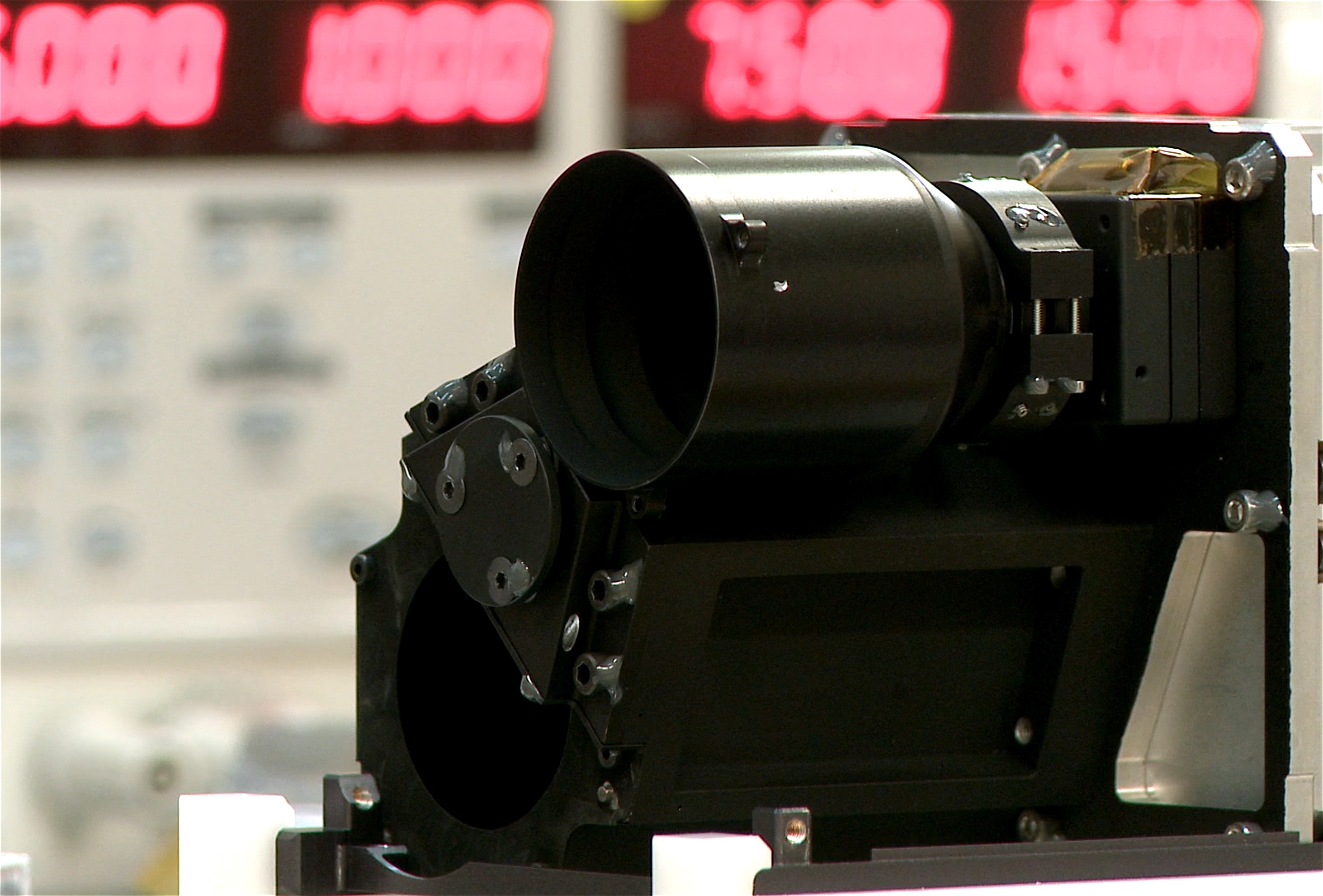
PFP comprises a two-mirror telescope, a Piezo Stage for jitter compensation, a single-pixel avalanche diode and support electronics. The light coming from the target star is collected by a small optical telescope with an aperture diameter of 3.7 centimeters and is injected in a Single Mode Fiber (SMF) placed in the focal plane of the telescope and brought to the Single Pixel Avalanche Diode (SPAD) where the incoming photons are counted.
The telescope employs a compact 30° off-axis Newtonian design with a focal length of 14.8 centimeters and an aperture ratio of F/D=4, constrained by the requirement of matching that of the optical fiber for proper injection. The telescope’s parabolic primary mirror is 50 millimeters in diameter and has been slightly oversized to ensure optimal image quality on the edges; the secondary mirror employs a plane design with a diameter of 22 millimeters.
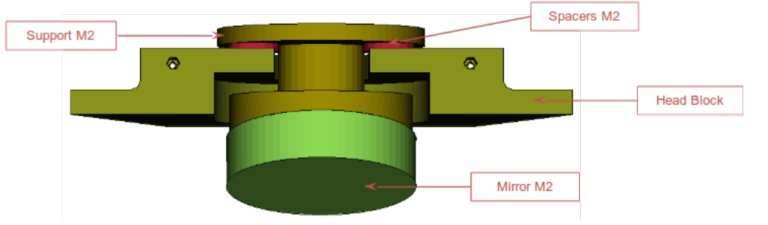
The secondary mirror is installed on a mechanical assembly that has three peelable washers that allow the mirror position to be fine-tuned with respect to the alignment with the primary parabolic mirror. All elements of the optical system, including the mirrors, are made of aluminum in order to keep thermal variations homogeneous across the entire structure and thus minimizing their effect on the optical quality of the instrument.
Given the fiber’s very small diameter of 3 millimeters and the size of the star image on the focal plane nearly matching that size, a deliberate mechanism is needed to properly keep the star image on the SMF and inject all incoming photons.
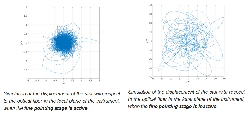
This is realized via a tracking system and Piezo-Stage which keep the small fiber centered on the star, even in the presence of pointing errors and unavoidable jitter from the attitude control system. The SMF resides on a dual-axis Piezo-Stage which can move the fiber in the focal plane over a 450 x 450-micrometer area. PicSat’s attitude determination and control system has sufficient precision for keeping the image within the accessible range of the stage and acquisition is accomplished through a scanning mode that moves the fiber over the full range of motion to find the star and switch into tracking mode.
However, excellent tracking of the target star is not enough when attempting to reach a photometric precision in the 100 parts-per-million/hour range. Some variations in the Point Spread Function of the instrument can be expected due thermal variations in the optics which is a known cause for variations in photometry. To correct this, the PSF is estimated through measurements of its most critical parameters – instrument focus and anastigmatism. This is accomplished by the Piezo-Stage constantly modulating the position of the fiber around the central position of the star.
The PFP support electronics are consolidated on a single board, tasked with collecting data from the avalanche diode, communicating with the satellite platform and running the tracking algorithm. Its central processing unit is a 72MHz microchip which was specially space qualified for this mission as it has the required low-power, high-performance characteristics needed to run the 1kHz Kalman filter algorithm.
The Piezo-Stage is driven via two digital-to-analog converters and a 150V high voltage source, allowing the stage to be moved at 0.01µm increments. The SPAD (Single Pixel Avalanche Diode) receives a 5V power bus and a -25V bias voltage with high stability (100µV) to maintain the required photometric precision. A 4b-bit hardware counter receives the electron cascade signal from the SPAD and its operation is regulated through a discrete 3.3 V signal from the hardware timers of the PFP electronics to ensure proper timing of the integration cycles.
A dedicated Thermo-Electric Cooling system is built into the SPAD and controlled by a separate control system to manage the temperature of the pixel between 2 and 16°C at a stability of 0.1°C over extended periods.