
CANYVAL-X – Tom & Jerry
CANYVAL-X is a two-satellite CubeSat mission aiming to demonstrate a Vision Alignment System that could enable a virtual telescope with very long focal length for application in cutting-edge heliophysics and astrophysics missions. The mission consists of a 2-Unit CubeSat, nicknamed Tom, and a 1-Unit satellite “Jerry” that will maintain optical alignment over a distance of ten meters for time frames sufficient for astronomical observations.
CANYVAL-X stands for CubeSat Astronomy by NASA and Yonsei using Vision ALignment eXperiment and involves NASA’s Goddard Spaceflight Center, Korea’s Yonsei University and the Korea Aerospace Research Institute (KARI). Under the international collaboration, Yonsei and KARI are building and testing the 2U and 1U CubeSats while Goddard provides the µCAT micropropulsion system.
The mission’s primary objective is demonstrating alignment between two satellites along an inertial line of sight to a distant celestial target over periods of time sufficient for an astronomical observation. Although tandem-flying experiments have already been conducted, the feat of keeping two satellites in alignment to observe a target will be a first and would enable virtual telescopes with extremely high focal lengths to become a reality.
One application of the technology demonstrated by CANYVAL-X is a two-satellite solar chronograph comprising an occulter satellite that is placed in the line of sight of the sensor-craft and the sun so that the bright sunlight is blocked and the spectrographic sensor can complete studies of the much fainter coronal structure. Presently, spaceborne chronographs house the occulter and spectrograph within the same telescope assembly at very close distances which imposes limits on their scientific performance.
To achieve a vision alignment between the two satellites, the system needs to be able to complete relative orbit determination and control as well as relative attitude control in order to maintain vision alignment for durations of several minutes.
The CANYVAL-X mission architecture calls for one of the two satellites to be actively controllable (Tom) to follow the the orbital progression of the other member of the system which lacks a propulsion system but is capable of coarsely setting its three-axis orientation in space. Per the mission concept, Tom employs a micro-propulsion system to follow Jerry’s orbital progression and the two use a laser-guided optical navigation system to set the proper relative geometry once they are at the proper distance with Jerry holding its attitude relative to the sun and Tom moving onto the vector joining Jerry and the sun.
The Relative Orbit Determination System employs GPS-based orbit determination systems on both satellites and an inter-satellite communications link to provide the GPS information from the passive craft to the propulsive member of the combo. As such, Jerry constantly calculates its orbit and transmits it every five minutes via a 435.020 MHz UHF link to Tom which then calculates the propulsive inputs required to link up with Jerry.
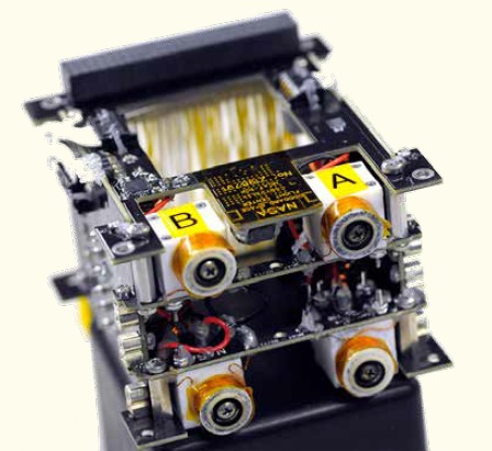
Tom is equipped with an µCAT (Micro Cathode Arc Thruster) developed by NASA Goddard and George Washington University to precisely control its orbit to link up with Jerry and follow its orbital decay. The µCAT system of the CANYVAL-X mission employs four thruster heads, each capable of a maximum impulse of 0.05 mNs, and all installed on the same body axis. Per Tom’s orbit control algorithm, it will calculate the direction of the required impulse, use its three reaction wheels to re-orient to the appropriate attitude and fire the proper thrust in each sampling time step.
Each µCAT thruster head consists of two coaxial electrodes that are separated by several millimeters of Electric Solid Propellant with a Magnetic Coil on the forward end of the thruster. Each thruster head measures one centimeter in diameter and 2.29 centimeters in length. The Anode is located in the center of the thruster while the titanium Cathode material builds the external shell of the thruster. The solid propellant used in these thrusters can only ignite when an electric current is applied and only sustain operation as long as the current is present. This allows for precise control and a reliable ignition.
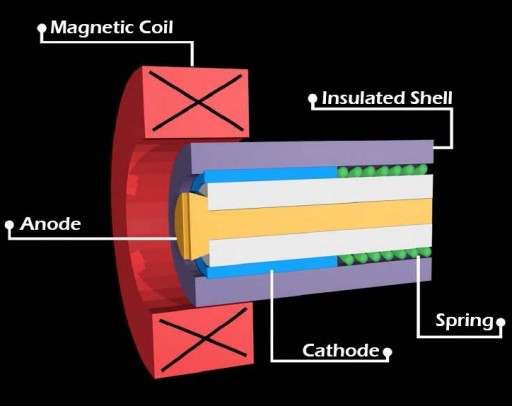
Conventional solid-fueled thrusters can not be controlled – once ignited, they burn until expending all their propellant. Thrust on the µCAT is generated through outstreaming electrons and atoms. The µCAT thrusters can operate at frequencies between one and 50 Hz, generating impulse bits of 2µNs per pulse and operate at a specific impulse of 2000 to 3000 seconds, much higher than conventional liquid-fueled thruster systems. Tom’s entire µCAT package fits into a 6 x 9 x 9-centimeter envelope.
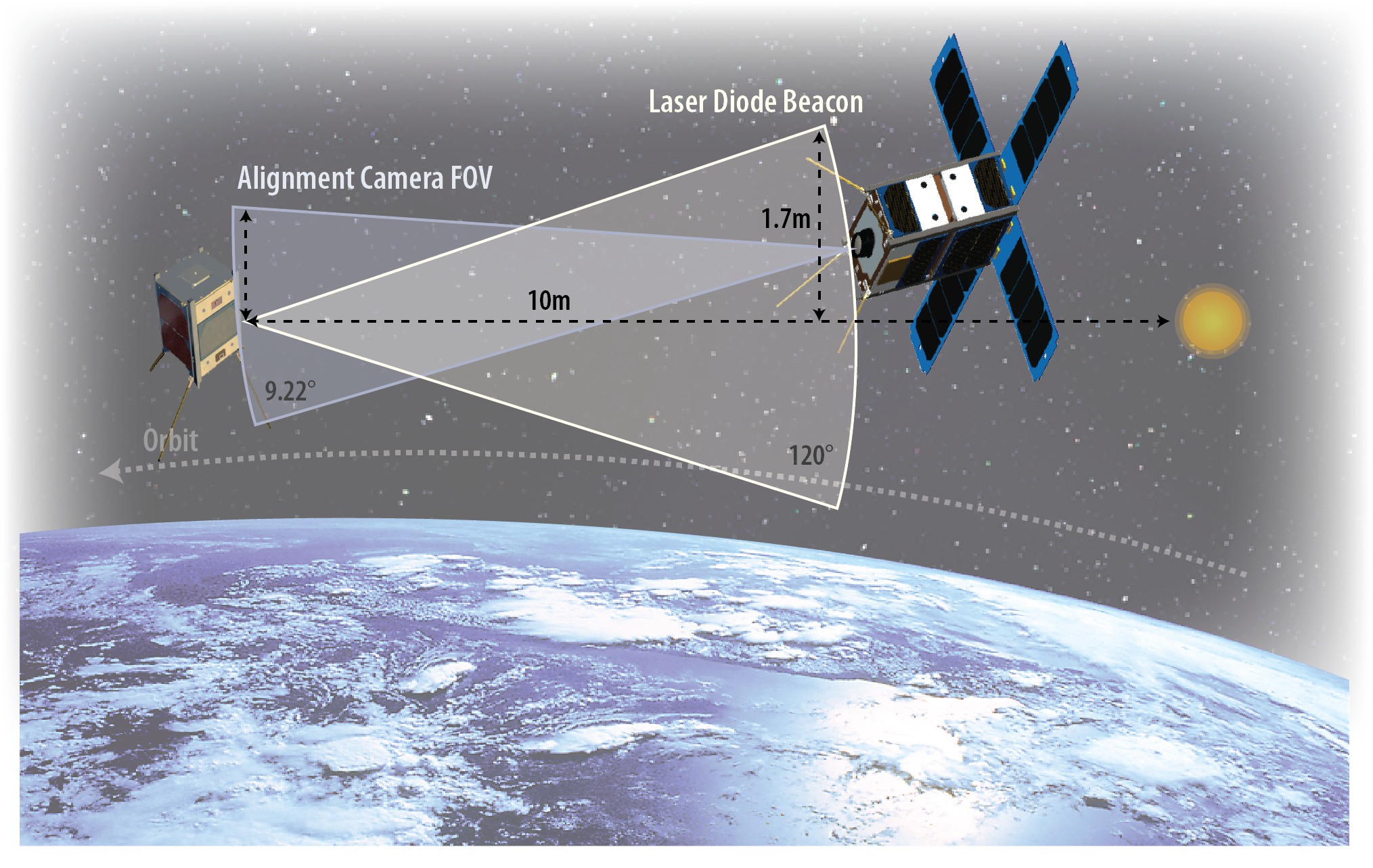
The Vision Alignment System consists of a laser beacon on Jerry and a visual camera on Tom. When a Vision Alignment Sequence begins, Jerry employs a sun sensor to orient toward the solar vector with the laser diodes pointed to the sun. Tom will then use the laser diode projection as navigation source and move into position on the solar vector at a distance to 10 to 50 meters to Jerry. To keep the inertial alignment, Tom will control its position on the transversal plane of Jerry and the Sun via its thrusters and attitude actuators.

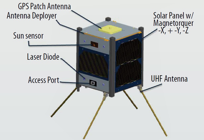
Jerry uses a typical 1U CubeSat structure with five of its six external panels occupied by solar cells to generate an orbit-average power of 2 Watts, fed to a 10 Watt-hour battery and distributed to the various users on the satellite. The solar panels double as coarse sun sensors to determine the approximate solar vector to move the sun into the field of view of a Fine Sun Sensors which is used for fine-pointing toward the sun with an accuracy better than five degrees for the experiment.
The 810-gram Jerry employs a NanoMind Onboard Computer, a custom Attitude Determination and Control Board facilitates the inertial sensor and magnetometer in use for basic attitude determination and the magnetic torquers for attitude actuation. The GPS antenna and OEM615 receiver provide the data needed for orbit determination with an accuracy of ten centimeters on all axes and a NanoCom UHF communications terminal is used for the inter-satellite link and the 9.6 and 4.8 kbps down- and uplink.
Jerry’s three laser diodes deliver a beam pattern spanning -/+60 degrees, allowing Tom to acquire the laser pattern from up to 1.7 meters off the solar vector when at a distance of 10 meters.


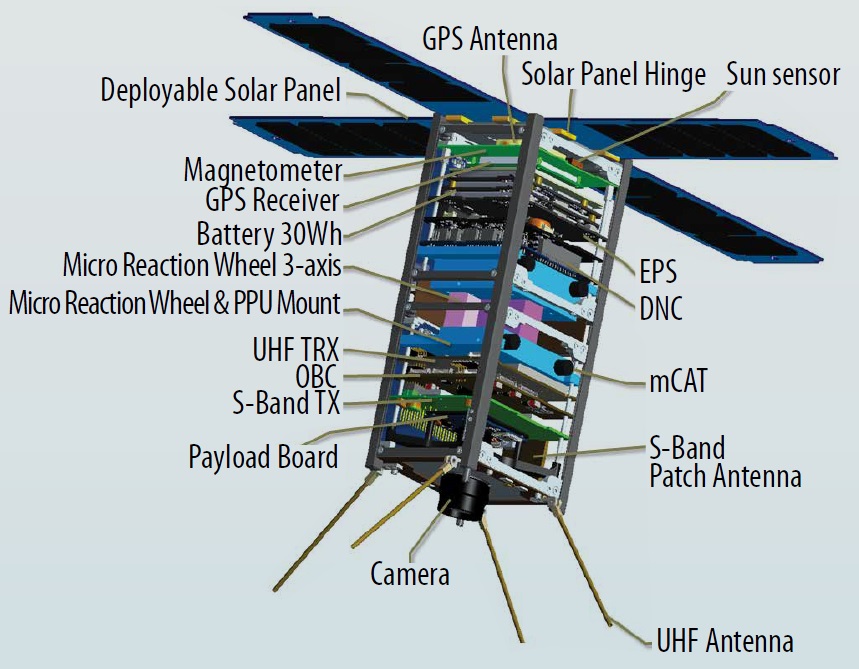
Tom uses much of the same systems as Jerry (NanoMind OBC, GPS chain, NanoCom communications) with a number of changes an additions given its more advanced functions as the maneuverable of the two satellites. These include the addition of the µCAT module, a dedicated ADCS Cube Computer to run the attitude determination and control hardware, reaction wheels as attitude actuators with assistance from magnetic torquers, an S-Band downlink system (100kbps) and a more powerful Electric Power System from Clyde Space comprising 12 strings of solar cells on body-mounted plus four deployable solar panels and a 30Wh battery.
Tom’s visible camera system for detection of the laser beacon of Jerry has a bandpass of 610 to 660 nanometers to eliminate ambient light from various sources. NanoCam has a 2048 x 1536 CMOS sensor and a 35mm lens; it has a field of view of 9.22 degrees and a Fine Sun Sensor assists during initial acquisition of Jerry by putting Tom sufficiently close to the solar vector. All in all, Tom weighs 2.25 Kilograms and its power system generates a peak power of 13 Watts when in harvesting mode – pointing the cross panels at the sun to fully charge the battery before a Visual Alignment Cycle that requires simultaneous operation of the µCAT, reaction wheels, GPS, camera and ADCS/OBC computers.
Attitude Determination and Control on Tom exceeds 1°, the relative orbit determination algorithm has a minimum precision of ten centimeters and the relative orbit control system exceeds and accuracy of one meter.

Tom and Jerry launch as a single payload and are joined by a Satellite Separation System on the z-panels of the two satellites. On Tom’s side, there is a heat resistor of 10 Ohm and the two satellites are bound using a dynamo wire that melts at high temperature. A voltage of 7.8V is applied to initiate the separation by severing the wire and push the two satellites apart with a loaded spring. Separation is completed after the two satellites have been tracked in orbit and stabilized their orientation. Once on their own, the two would drift apart by 4.55 Kilometers per orbit due to orbital mechanics and their different size/mass properties, requiring Tom to actively keep up with the passive Jerry satellite.
