
MiRaTA Satellite Overview
MiRaTA (Microwave Radiometer Technology Acceleration) is an Earth observation technology demonstration CubeSat mission developed at MIT Lincoln Lab to test a miniaturized multi-band microwave radiometer and compact GPS occultation payload that could build the foundation of a future CubeSat constellation for the collection of global weather data at very rapid revisit intervals.
The MiRaTA project is part of NASA’s InVEST (In-Space Validation of Earth Science Technologies) Program aiming to develop and test small instruments and remote-sensing subsystems that can advance the current state of technology to enable relevant Earth science measurements via smaller satellite platforms. MiRaTA will validate a new ultra-compact and low-power microwave radiometer for the collection of atmospheric profiles, a GPS occultation receiver and antenna for tropospheric radio occultation sounding and a novel approach to radiometer calibration using GPS radio occultation measurements. The goal is to advance the technology readiness level of both components from TRL 5 to 7 at the conclusion of the mission.
MiRaTA is the first ever implementation of co-located radiometer and occultation sounding and the first CubeSat implementation of temperature/humidity radiometric sounding and occultation sounding. The mission will not only validate multiple subsystem technologies but also demonstrate a new sensing technique that could dramatically enhance the capabilities of future weather and climate observatories. Shrinking an operational radiometer and GPS RO system to fit onto a nanosatellite platform furthermore enables new architectural approaches for low-cost, high-return missions in the field of operational meteorology.
The calibration approach developed for MiRaTA calls for a pitch up/down maneuver once per orbit to complete a radiometer pass and GPS occultation across overlapping volumes of the atmosphere through Earth’s limb where sensitivity, calibration, and dynamic range are optimal. For an operational mission, this type of measurement will allow for an intra-satellite calibration approach no-longer relying on blackbodies and other calibration sources. For MiRaTA, concurrent radiometer and GPS RO data will be compared with ground-based radiosondes and other satellite observations to validate the measurements.
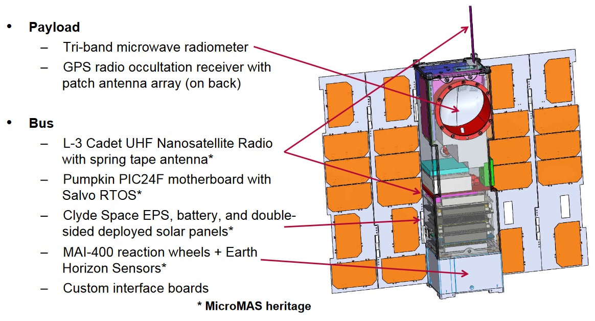
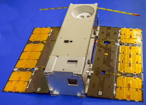
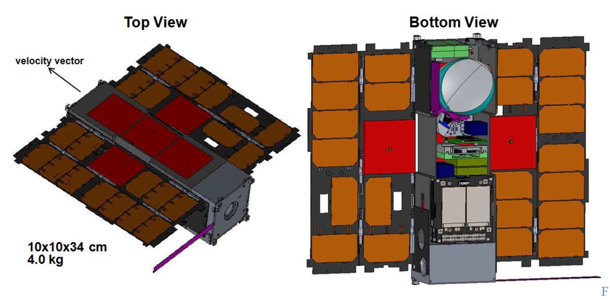
MiRaTA is a three-unit CubeSat, 10 x 10 x 34 centimeters in size with a mass of under 4.5 Kilograms, using a platform that builds on the MicroMAS (Micro-sized Microwave Atmospheric Satellite) though with a number of simplifications, e.g. eliminating active scanning mechanisms and reducing deployable structures to a pair of solar panels and a simple tape-spring UHF communications antenna. Per the instrument requirements, the radiometer resides on the nadir-facing panel of the satellite while the GPS antennas face toward zenith.
Electrical power is provided by two double deployed solar panels that are hinged on the zenith-pointed satellite panel and feed power to a 20 Watt-hour Li-Ion battery assembly. An EPS card conditions the power buses at 3.3, 5 and 12 Volts and provides bus protection with the overall EPS design calling for a typical energy requirement per orbit around 8.3 Watts and a 20% design margin at satellite end of life. The two solar panels can deliver a peak power of 24.8 Watts.
The attitude control system of the satellite consists of reaction wheels that are used to stabilize the 3U satellite bus and keep it in an Earth-pointing attitude for normal data collection and facilitate the once-per-orbit pitch maneuver for instrument cross-calibration.
Attitude determination is provided by a series of sensors – an Inertial Measurement Unit and magnetometer are used in the initial attitude acquisition and de-tumble before the satellite begins processing sun sensor data in a TRIAD navigation method with Earth horizon sensors in use for verification of the correct attitude for science operations.
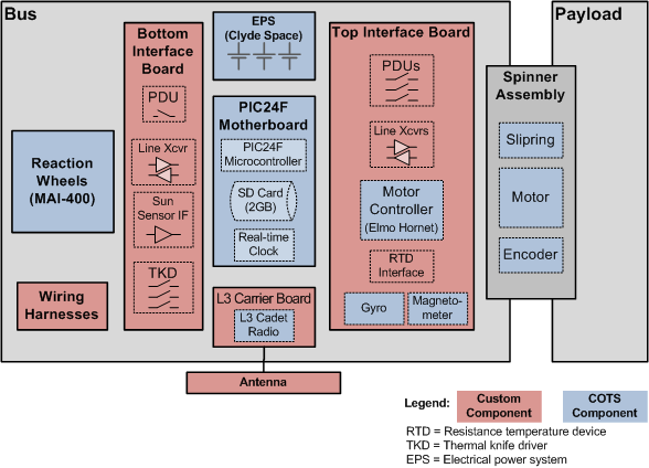
Attitude actuation uses a combination of torque rods and reaction wheels integrated within the MAI-400 assembly provided by Maryland Aerospace. In addition to two Earth horizon sensors within MAI-400, the MiRaTA satellite hosts a third sensor to assist in the pitch-up maneuver.
The satellite motherboard is a standard CubeSat board provided by Pumpkin using a PIC24 microcontroller as flight computer that runs on Pumpkin’s Salvo Real Time Operating System. The satellite uses CubeSat-Kit interfaces for the reaction wheels, communication system and mass memory while the PCB is used for the attitude sensors, motor controller and payload. Payload Data is stored in an SD card.

Communications are accomplished with a half-duplex L-3 Communications Cadet UHF Nanosatellite radio. Operating at a frequency of 450MHz for uplink, the system achieves a data rate of 9.6kbit/s with GFSK modulation and 19.2kbit/s with FEC. Downlink uses the 468MHz UHF frequency for low data volumes as the payload generates a data volume of about 19 kbit/s when operating.
The MiRaTA nanosatellite hosts two complete instrument systems: MWR – the Microwave Radiometer, a tri-band atmospheric sounder, and CTAGS – the Compact TEC (Total Electron Count)/Atmosphere GPS Sensor. Both are operated to allow cross-comparison and cross-calibration to validate a new approach for potential future exploitation.
A microwave radiometer observes the radiance of the atmosphere at microwave wavelengths that are detected by an antenna which uses support electronics to amplify and record the signals of given frequency bands. The detected power level for each frequency band is used to generate temperature and moisture profiles through the various regions of the atmosphere. Elements present in the atmosphere have different absorption spectra, allowing radiometers to observe different atmospheric constituents.
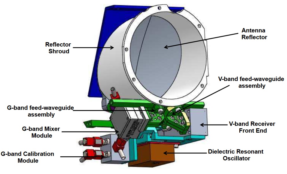

The MWR instrument is a passive microwave radiometer collecting co-registered observations over three frequency bands via two radiometer subsystems. Two scalar feed horns illuminate an offset parabolic reflector that yields pitch-plane-aligned beam widths of 1.25 and 5.0° for the G- and V-Band systems, respectively with a beam efficiency higher than 95. The system has been designed with scalability in mind, allowing the aperture to be enlarged for a 6U CubeSat mission.
The first subsystems hosts the systems of the 52-58 GHz V-Band channel, comprising the V-Band front end, low-noise amplifier, mixer coupled to a 81.47 GHz Local Oscillator, intermediate frequency amplifier and a compact back-end to provide six channels with temperature weighting functions approximately uniformly distributed over the troposphere and lower stratosphere up to an altitude of 20 Kilometers.
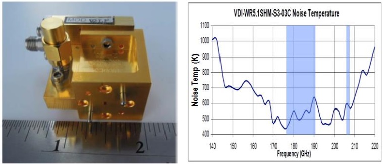
The second subsystem builds the G-Band sensing system covering a pair of channels at 175-191 and 206-208 GHz with a front end operating between 175.3 and 208.4 GHz and subharmonic detection chain with a 91 GHz Local Oscillator and conventional intermediate frequency spectrometer and back end. Both MWR subsystems share a common redundant dielectric resonator oscillator with multiplication stages in each of the local chains to match the required frequencies.
The addition of the CTAGS instrument allows MiRaTA to combine the benefits of passive sounding and GPS Radio Occultation measurements to achieve highly accurate calibration with dense geospatial sampling. Benefits of using GPS RO are primarily found in the accuracy of measurements which easily achieves 0.1 K for vertical temperature profiles in the upper troposphere and lower stratosphere; however, GPSRO measurements have sparse geospatial coverage with daily measurements ranging between a few hundred and a few thousand while traditional microwave radiometers can conduct continuous measurements and easily achieve global coverage.

The issue that arises for microwave instruments is an elaborate calibration requirement to ensure radiometric accuracy which, for typical missions, relies on internal blackbodies as a hot reference point and soundings of cold space as cold reference as well as solar irradiance and lunar calibration measurements. The combination of a radiometer and GPSRO instrument will allow a two-way calibration without Internal Calibration Targets which often drive the instrument design and add mass to the sensors.
GNSS occultation measurements for atmospheric and ionospheric measurements is a proven method for the acquisition of temperature, pressure and humidity profiles from high altitude to near-ground level. The science and methodology behind GNSS occultation measurements is well established and has been employed for many scientific projects as well as operational meteorology systems.
GPS operates a constellation of approximately 30 active satellites in six orbital planes, 20,000 Kilometers in altitude, transmitting different L-Band signals used for navigation and precise timing applications as well as a wide variety of other applications including meteorology. At least four satellites are simultaneously visible from any position on Earth, an observer in Low Earth Orbit will usually see 12 satellites at any time.
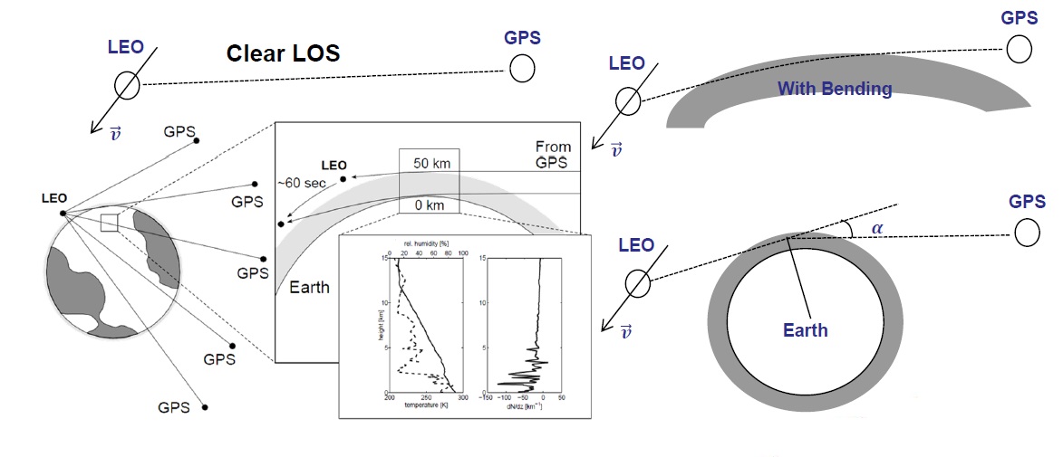
Occultation measurements make use of the fact that Earth’s atmosphere can alter the properties of a GPS signal to extract relevant meteorological parameters. The measurement is done by a satellite that sees its line of sight to a GPS satellite penetrate Earth’s atmosphere as the GPS satellite either rises for sets from the receiver’s vantage point.
CTAGS flown on MiRaTA is based on the successful CTECS (Compact Total Electron Content Sensor) hosted by the OSIRIS-3U CubeSat. The advanced system employs a more compact and capable GPS receiver and a high-gain patch antenna array to extend measurements from the ionosphere into the lower atmosphere, allowing CTAGS to collect ionospheric and atmospheric measurements down to at least 20 Kilometers in altitude. The instrument consists of four primary components: a multi-element antenna array, single patch antenna for precise orbit determination, low-noise amplification stage and a NovaTel OEM628 GPS receiver.
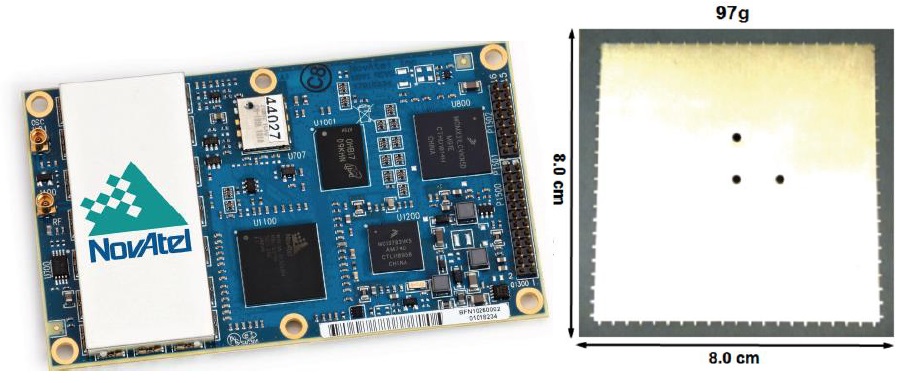
CTAGS combines multiple heritage CTECS antenna elements and the higher gain allows the instrument to remain locked on GPS satellites as they set behind the Earth’s dense atmospheric layers for low-altitude measurements. The receiver can track up to 60 dual-frequency satellites at any time, allowing for simultaneous atmospheric, ionospheric, and navigation observations, utilizing the L1, L2 and L2c signals for refraction measurements from which the total electron content/atmospheric properties and their vertical profiles can be extracted. CTAGS makes measurements of the L1/L2 pseudorange and L1/L2/L2c phase, taking advantage of the satellite’s relatively low orbit to measure a large amount of density above the satellite.
The calibration of radiometers has proven to be challenging even for flagship missions like the ATMS (Advanced Technology Microwave Sounder) on the NPP and JPSS satellites and the GMI (Microwave Imager) on GPM (Global Precipitation Mission). Research has shown that biases, despite high-fidelity calibration approaches, may be as high as 2 Kelvin.
MiRaTA proposes a two-pronged calibration approach that promises much greater accuracy while reducing complexity and instrument size through the use of the combination of a noise diode for frequent calibration of the radiometer and the less-frequent GPSRO measurement as a through-the-antenna end-to-end calibration of the instrument and as cross-check for the noise diode to calibrate its accuracy and stability.
Noise diodes are used in the radiometer front end to inject a calibration signal into the radiometer with relatively low loss, though susceptible to signal drifts and not representing a complete through-the-antenna calibration. Furthermore, integrating noise diodes into the signal path requires a switch which adds signal losses that can be of significance when aiming for large-area coverage over short time scales.
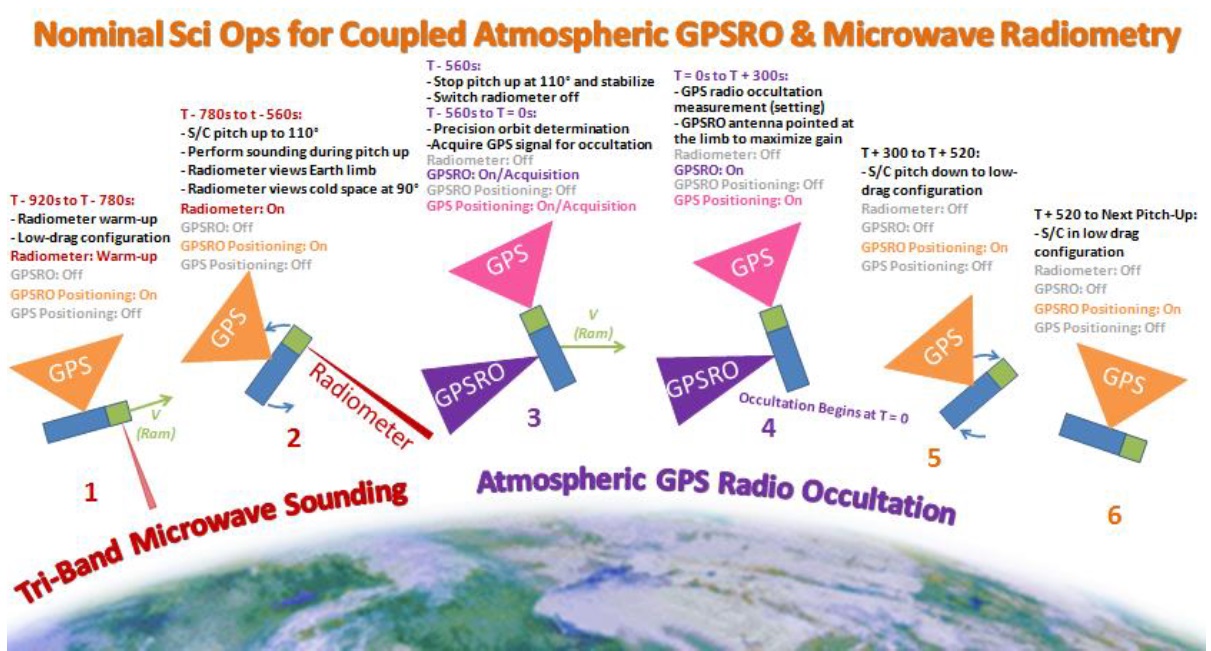
Operationally, the MiRaTA concept will be realized by slewing the spacecraft from a radiometer-nadir attitude to a 90-105-degree pitch angle and back so that the radiometer and GPSRO instrument can sound the same area of Earth’s limb with very little time difference. The sequence will take between 22 and 32 minutes to complete and requires at least one or two GPS satellites to set behind the atmosphere, as seen by the CTAGS instrument.
The mission ground software is in charge of computing favorable opportunities by cross checking the satellite’s orbital parameters, CTAGS and MWR look angles and relative geometry with GPS satellites to isolate opportunities where the GPSRO and MWR fields overlap sufficiently – also taking into account onboard resources like power and reaction wheel saturation. These are then uplinked to the satellite as time-tagged command sequences and executed autonomously. Mission simulations predict two to three favorable opportunities to be available per day with overlaps of five to seven minutes.
The MiRaTA mission aims to collect at least 100 concurrent GPSRO and MWR measurements with a radiometric accuracy achieved through the new cross-calibration process matching that of the Joint Polar Satellite System (1.5K rms) down to 20 Kilometers (requirement) or 10 Kilometers (goal).
