
Antares (200 Series)

The Antares 200 Series is a family of medium-lift Space Launch Vehicles operated by Orbital ATK as an upgraded version of the original Antares Series 100 that was phased out after a launch failure in 2014. Primarily designed to lift Orbital ATK’s Cygnus cargo craft for Space Station resupply missions, Antares can also lift satellite payloads to a variety of orbits.
The Antares 200 series uses the original two-stage Antares design with a first stage built in the Ukraine and a solid-fueled second stage manufactured by Orbital ATK with options of adding a third stage for high-energy missions. The only change to the 100 series is a switch from the AJ26 engines that had been identified as the culprit in the October 2014 launch failure that claimed the loss of the Cygnus Orb-3 spacecraft.
A switch from the converted NK-33 engines built in the 1970s had been planned prior to the failure and was accelerated after the incident. The 200 series uses a pair of RD-181 engines built by NPO Energomash in Russia.
Another upgrade of Antares will be introduced with the 300 Series that will feature a re-structured first stage to enable the RD-181 engines to be run at their full thrust setting and provide the maximum performance to the vehicle.
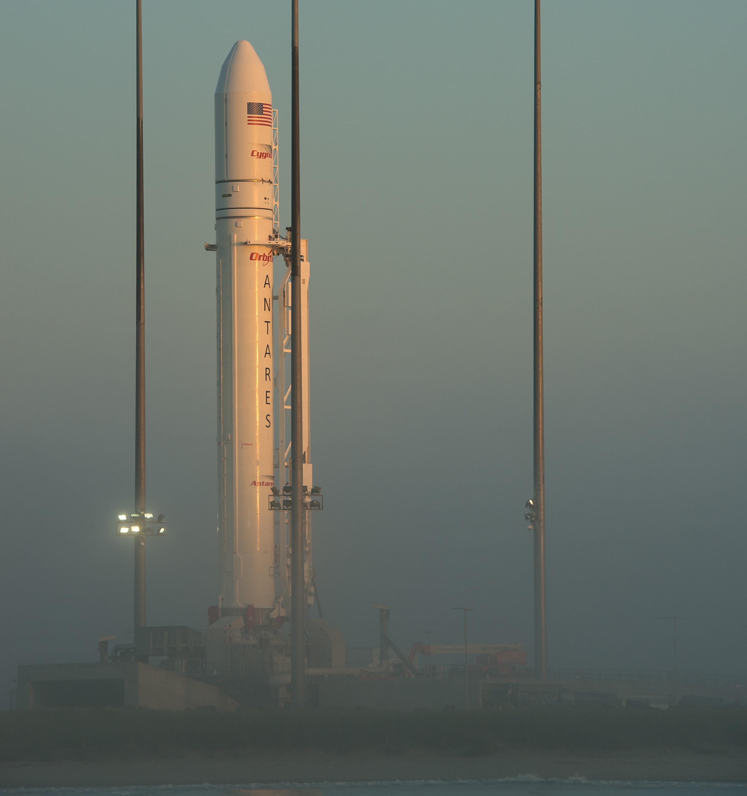
Antares is operated from the Mid-Atlantic Regional Spaceport at NASA’s Wallops Flight Facility, however, the vehicle is also compatible with the Western Range at Vandenberg Air Force Base, the Eastern Range at Cape Canaveral Air Force Station and the Kodiak Launch Complex, Alaska.
Orbital ATK (then Orbital Sciences) developed Antares under a Commercial Orbital Transportation Services (COTS) contract that the company was awarded from NASA to demonstrate cargo deliveries to the International Space Station. After completing the COTS program, Orbital entered the Commercial Resupply Services Program with the Antares/Cygnus combination.
NASA has booked an initial eight ISS resupply flights of Cygnus under Commercial Resupply Services for a total contract volume of $1.9 billion. Three additional Cygnus missions were booked by NASA in 2015 as an extension to the existing CRS Phase 1 contracts.
Orbital ATK is part of the Phase 2 round of CRS contracts together with SpaceX and Sierra Nevada Corporation with a combined contract value of up to $14 billion, covering ISS cargo needs from 2019 through 2024.
The launch vehicle was originally known as Taurus II, but was renamed in late 2011 after the original Taurus rocket encountered a pair of launch failures. Antares made its first flight in April 2013 as part of the A-ONE demonstration flight that carried a dummy payload. The first Cygnus mission was completed five months later and marked Orbital’s first successful cargo delivery to ISS.

The Orb-3 mission was lost in a dramatic launch failure on October 28, 2014 when the Antares rocket suffered a catastrophic fault within one of its AJ26 engines less than 15 seconds after liftoff, resulting in a large explosion when the vehicle impact the launch facility causing considerable damage to the ground systems architecture. The most probable cause of the failure was an explosion in the Liquid Oxygen turbopump of the AJ26 engine installed in the Main Engine 1 position, likely due to a material defect on the engine.
At the Wallops Flight Facility, a $15 million repair effort was finished in September 2015 to restore Pad 0A to a functional state, ready to resume Antares missions. The first flight of the Antares 200 series is to be preceded by propellant loading tests at the launch pad as well as an engine hot fire to clear the new vehicle and repaired facility for the first 200 series launch in July 2016.
Antares Specifications
| Type | Antares |
| Height | 42.5m |
| Diameter | 3.90m |
| Launch Mass | 298,000kg (230) |
| Mass to LEO | 7,000kg (230) |
| Mass to GTO | 2,700kg (232) |
| Mass to SSO | 3,000kg (231) |
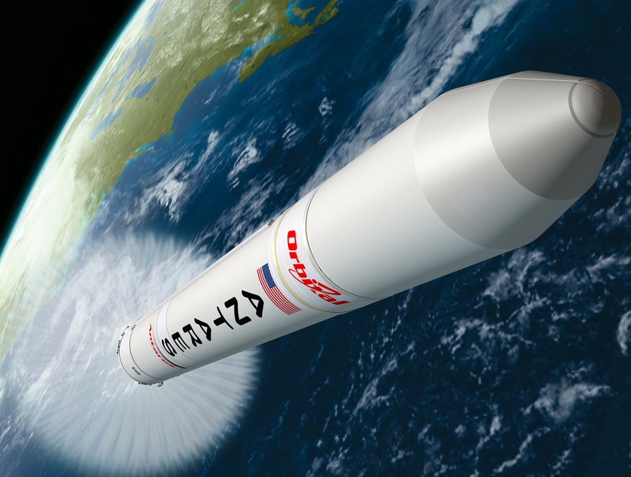
The Antares launch vehicle is a two stage rocket that can be fitted with different second stages and allows the addition of a third stage for high-energy missions to be able to cater to a number of different payloads beyond the Low Earth Orbit cargo market.
The vehicle stands 42.5 meters tall and is 3.9 meters in diameter with a launch mass of around 298,000 Kilograms.
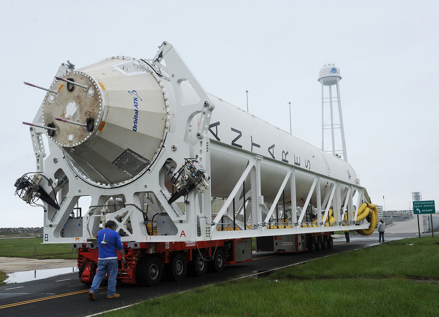
The first stage was designed by Yuzhnoye and is manufactured by Yuzhmash – both based in the Ukraine. In design, the first stage is largely based on the Zenit rocket’s first stage sharing the same diameter and basic architecture. When flying as a 200-series vehicle, Antares sports a pair of RD-181 engines built by Russian company NPO Energomash. The RD-181 is the export version of another Energomash engine, the RD-191 used by the Russian Angara launch vehicle family.

Antares’ second stage is a solid rocket motor built by Orbital ATK. Initially, Antares flew with a smaller second stage featuring a Castor 30A motor before upgrading to the Castor 30B and 30 XL version to increase the performance of the vehicle. As part of the 200 series, Antares will be exclusively flown with the Castor 30XL, though earlier reports indicated that the 30B variant was still available as an option.
For missions to Low Earth Orbit, Antares will operate as a two-stage rocket (230) and can deliver payloads of up to 7,000 Kilograms into orbit. Missions requiring high-energy deliveries can use a three-stage version of Antares either fitted with a Bi-Propellant Third Stage BTS (Antares 231) or a Star 48 Solid Rocket Motor (232). The Antares 232 version can deliver payloads of around 2,700 Kilograms to Geostationary Transfer Orbit.
First Stage
| Type | S1 Core Stage, Zenit Heritage |
| Bays | 5 |
| Dry Mass | 20,600kg |
| Launch Mass | 262,600kg |
| Diameter | 3.90m |
| Length | 27.6m |
| Fuel | Rocket Propellant 1 |
| Oxidizer | Liquid Oxygen |
| Fuel Mass | 64,740kg |
| Oxidizer Mass | 177,260kg |
| Tank Pressurization | Helium, up to 220bar |
| # Helium Bottles | 8 |
| Propulsion | 2 x RD-181 |
| Throttle Range | 47% – 100% |
| RD-181 SL Thrust | 1,922kN |
| RD-181 Vac Thrust | 2,085kN |
| Contingency Throttle | 105% |
| Impulse SL | 311.9s |
| Impulse Vac | 339.2s |
| Engine Length | 3.68m |
| Engine Diameter | 2.10m |
| Engine Dry Weight | 2,200kg |
| Thrust to Weight | 89 |
| Chamber Pressure | 262.6bar |
| Ox. To Fuel Ratio | 2.63 |
| Burn Time | 215sec |
| Attitude Control | Hydraulic TVC for Yaw, Pitch & Roll |
| Stage Separation | Hold Down Bolt Release |
The first stage of the Antares 200 series is identical to the 100 series with the exception of the engine bay hosting a pair of RD-181 engines instead of the AJ26 that powered Antares for its first four launches.
The stage was designed by the Yuzhnoye State Design Office and is manufactured by the Yuzhmash State Enterprise using Zenit heritage. Antares’ first stage is 27.6 meters long and 3.9 meters in diameter and contains Liquid Oxygen as oxidizer and Rocket Propellant 1 as fuel.
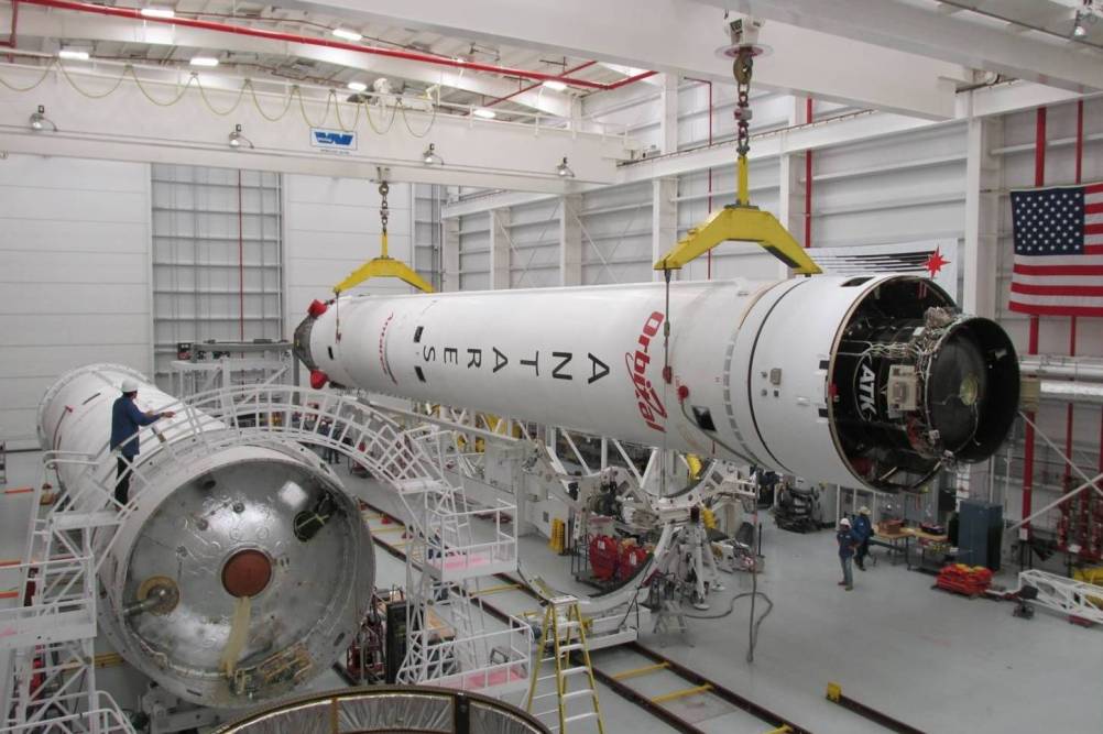
The Stage 1 assembly consists of the Stage 1 Core, the Main Engine System and the Flight Termination System. The Stage 1 Core is comprised of five bays and provides the structural support of the launch vehicle.
It includes propellant tanks and associated plumbing, pressurization systems, instrumentation and avionics. Fluid and electrical interfaces to the launch vehicle are facilitated within the aft bay structure of the first stage. The connectors mate with a launch ring that builds the interface between the vehicle and the launch pad.
The Liquid Oxygen Tank Bay and Rocket Propellant 1 Bay consist of their corresponding propellant tanks which feature level sensors to measure propellant levels during fueling and in flight. This measurement system is used by the engine controllers to determine engine mixture ratio adjustments to minimize leftover residuals in the tanks.
The RP-1 tank utilizes an aluminum waffle structure and it features a tunnel through its core to accommodate the LOX feedline. Routing the feedline from the LOX tank above to the engines through the RP-1 tank increases packaging efficiency.
The LOX tank is manufactured from solid aluminum and houses Helium Pressurant Bottles which are submerged in the LOX tank for gas storage efficiency.
Helium loading begins once the bottles are submerged in Liquid Oxygen in order to be chilled down to accommodate the Helium which is used to pressurize both, the RP-1 and LOX tanks. The pressurization system operates at a maximum pressure of 220 bar and supplies gas through a manifold of valves that are cycled open to regulate tank pressurization and propellant flow rates. Over-pressurization is prevented by emergency relief valves.
The remaining three bays are the inter-tank bay, the inter-stage bay and the aft bay that includes the Main Engine System.
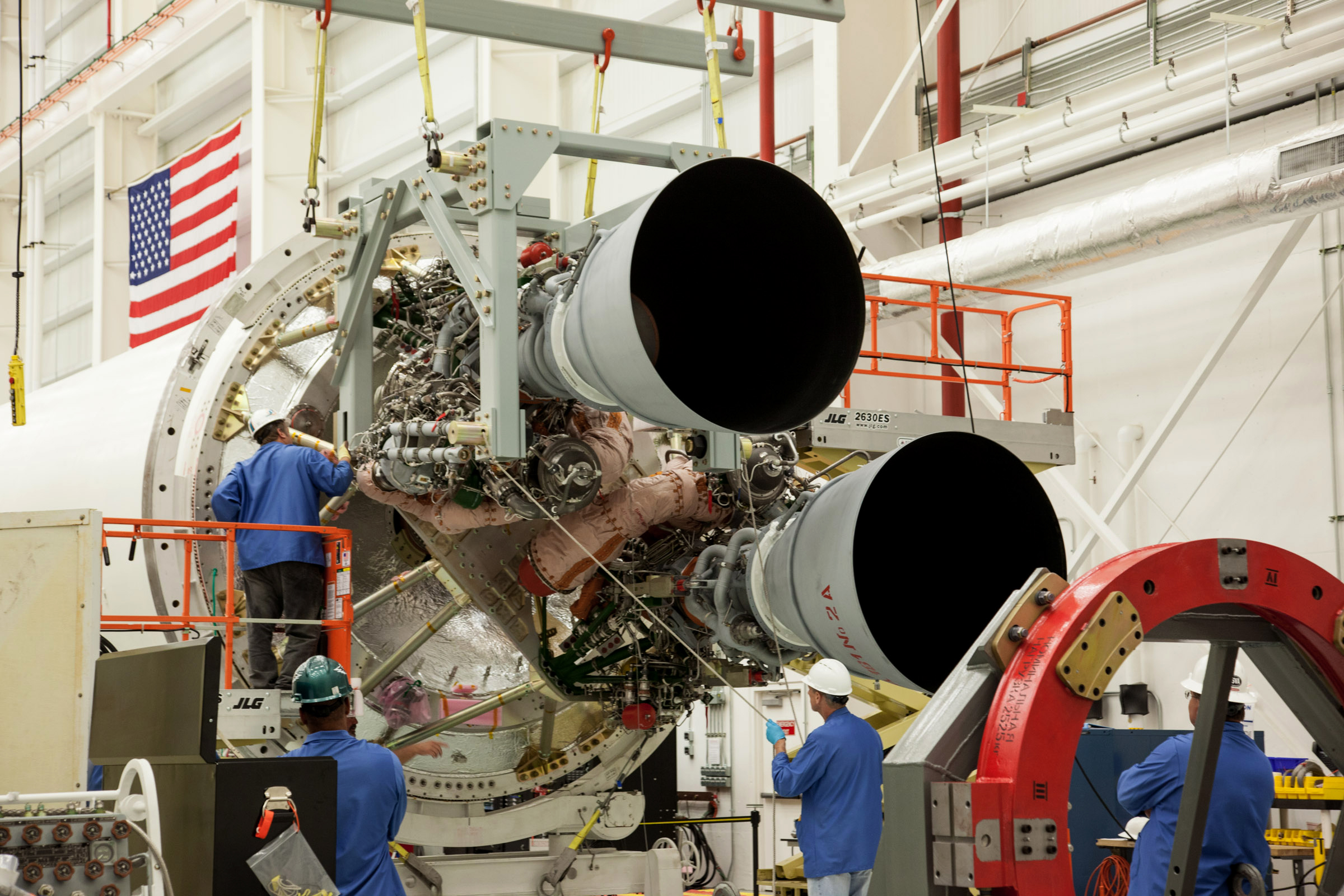
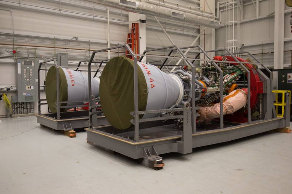
The Main Engine System of the Antares 200 and 300 series consists of two NPO Energomash RD-181 engines which represent modified RD-191 engines made specifically for foreign export and include structural interfaces adapted for integration with Antares.
RD-191 is a one-chamber version of the RD-171 engine used on the Zenit rocket that is based on the RD-170 designed for the Energia rocket. The NPO Energomash RD-171 had already been converted to the two-chamber RD-180 currently used on the Atlas V launch vehicle. In the process of designing the RD-180, a study of creating a one-chamber version was conducted and the development of the engine was started in the late 1990s.
RD-191 – sporting smaller turbopumps than its dual and four-chamber companions – was certified for use on the Angara rocket family in 2013 after over 130 hot fire tests. Another derivative of the RD-191 is the RD-193, a stripped-down version developed for use on the Soyuz 2-1v rocket as a direct replacement of NK-33 once the surplus engines have been used.
RD-193 – shorter and lighter than the RD-191 – completed its testing campaign in 2013. Certification of RD-181 was completed after seven firings in May 2015 and the first units arrived in the U.S. around mid-year.
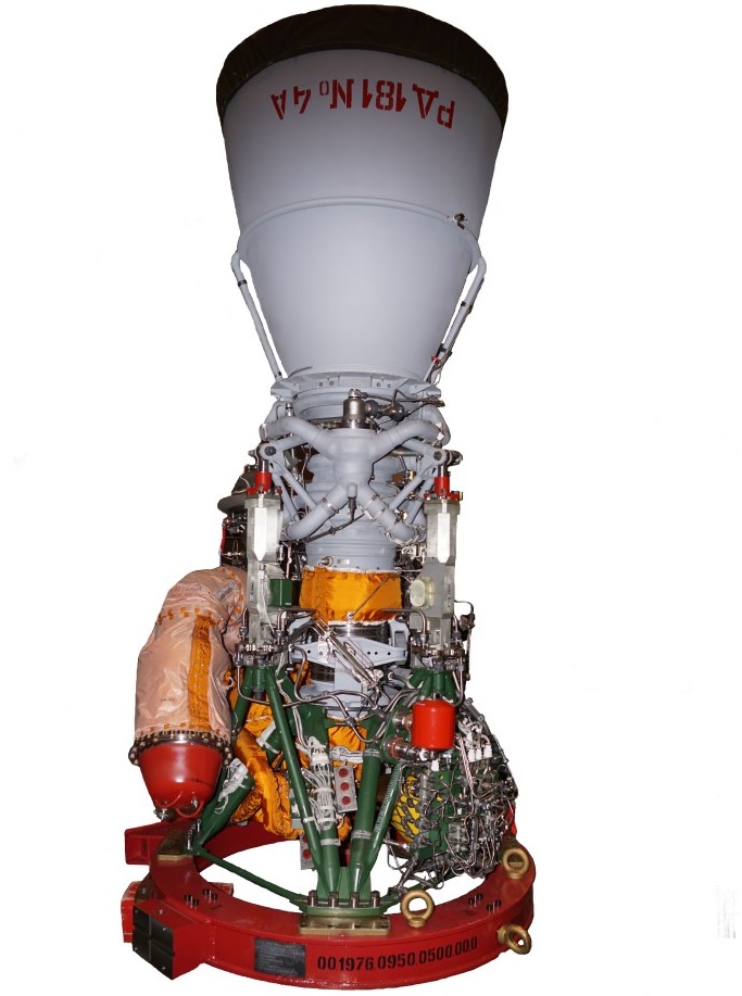
Overall, RD-181 is 3.68 meters tall and has a nozzle diameter of 2.1 meters. The engine has an inert mass of 2,200 Kilograms, slightly lighter than the RD-191 due to changes to the engine structure to permit its integration on Antares.
RD-181 delivers a sea level thrust of 1,922 Kilonewtons (196,000kgf) with a specific impulse of 311.9 seconds. Thrust rises to 2,085kN (212,600kgf) in vacuum conditions with a vacuum impulse of 339.2 seconds. Through its design, RD-181 is capable of deep throttling down to 47% of nominal performance. The engine can also operate at 105% of rated performance for short periods of time which is utilized in contingency scenarios.
Because of RD-181 uses a different mixture ratio than AJ26, delivers a higher thrust and does not require sub-cooled Liquid Oxygen, a change of tank sizes would be necessary to be able to reach the maximal performance of the vehicle.
For the Antares 200 series, existing 100 series cores will be used, requiring under-throttling the RD-181 engine which reduces overall performance but still achieves a 20% improvement of performance over the previous version of the rocket. For the 300 series, the first stage tanks will be modified for the RD-181 engines and the structure will be tweaked to deal with the higher thrust of the engines.
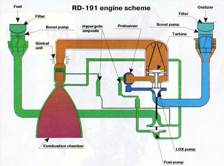
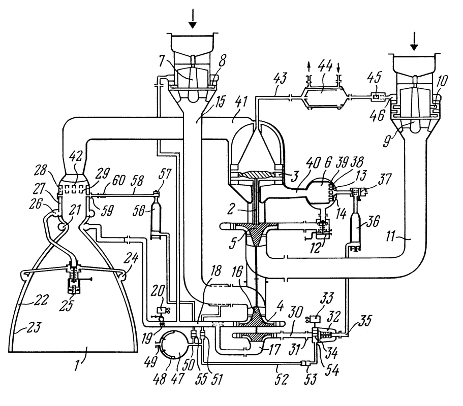
RD-181 uses a staged combustion scheme – burning all of the oxygen with little fuel inside a Gas Generator to produce a hot high-pressure gas to drive the turbine that powers the fuel and oxidizer turbopumps.
The engine features boost pumps at the fuel and oxidizer inlets that operate at a lower speed than the main pumps and create an engine inlet pressure sufficient for the operation of the turbopumps. The fuel boost pump is powered by a turbine driven by the fuel tapoff from one main pump (fuel returns to the inlet) and the oxidizer boost pump turbine is driven by a fraction of the hot gas from the gas generator that then enters the LOX flow and condenses.
All of the oxygen is then directed to the LOX impeller turbopump before reaching the Gas Generator. The Kerosene flow is directed into two portions using a two-stage turbopump. The Kerosene flow from the second pump stage (about 20% of total flow) is directed into the Gas Generator were it is burned in an excess of oxidizer, creating a high-pressure, oxygen-rich gas that drives the turbine. The RD-181’s LOX turbopump and fuel pumps are mounted on a single shaft. The turbine itself is a axial turbine using relatively thick blades and large clearance between the gas inlet and the blades to reduce the risk of damage. Nickel-alloys are used to endure the hot temperatures of the gas from the generator and the turbine uses cold oxygen for additional cooling.
The Kerosene from the first stage pump is directed to the combustion chamber and nozzle where it passes through heat exchangers as part of the regenerative cooling scheme of the engine. The engine uses three cooling paths, one entering at the combustion chamber, one entering at the nozzle throat and the third one entering at the nozzle exit.

After passing through the heat exchangers, the fuel is pumped into the combustion chamber where it is burned by the oxygen-rich gas coming from the gas generator. The mixture ratio is adjusted by a mixing valve located behind the first stage turbopump and the Gas Generator Temperature and engine thrust are regulated via flow valves ahead of the Gas Generator. RD-181 has a nominal mixture ratio of 2.63.
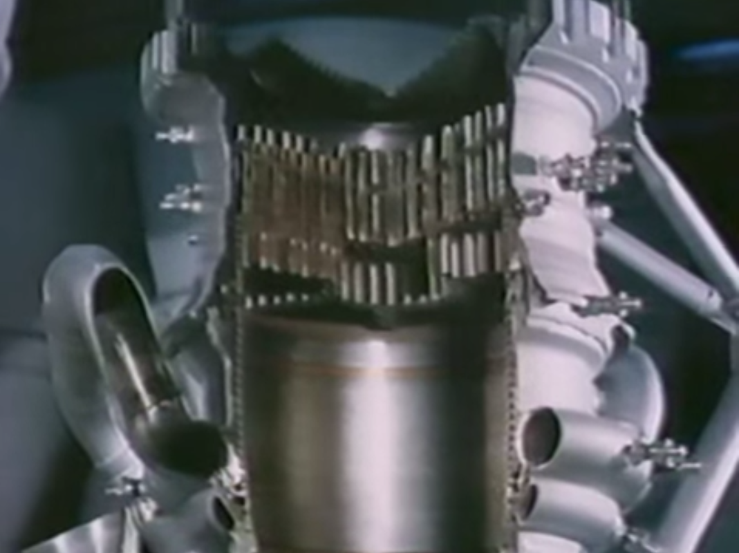
RD-181’s chamber consists of the mixing head, the combustion chamber and the nozzle. The injector uses small nozzles through which the components are introduced into the combustion chamber, forming a circular inner zone separated from an outer ring by protruding nozzles.
The outer ring is divided into six compartments using protruding nozzles through which propellants enter the chamber. Fuel and oxidizer-rich gas alternates between the seven compartments. This design allows a stable combustion and avoids combustion instability or the creation of hot spots. RD-181 operates at a nominal chamber pressure of 262.6 bar.
RD-181 uses a chemical ignition system based on Triethylaluminium (TEA) – a pyrophoric substance that immediately ignites upon exposure to oxygen. The TEA is stored in two closed ampoules – one in the fuel line directly ahead of the Gas Generator and one in the main fuel inlet to the combustion chamber. These ampoules use membranes to prevent the TEA from coming into contact with air.
For engine start, a dedicated spherical Kerosene, tank that is connected to both fuel lines via plumbing and associated valves, is filled with fuel and pressurized using high-pressure gas. Once the valves to the fuel lines and ampoules are opened, the high-pressure fuel drives pistons that are part of the ampoules to create a pressure inside the cavity that causes the TEA to be released into the Gas Generator and combustion chamber that have been filled with oxygen by that point after LOX valves are opened and the tank pressure causes oxygen to enter the engine.
Coming into contact with oxygen, the TEA ignites and starts the combustion process inside the Gas Generator and the main chamber. The combustion is sustained by Kerosene entering the GG and combustion chamber right after the TEA. Once the Gas Generator is running, the turbine spins up to speed and the turbo and boost pumps begin pumping propellants to the Gas Generator and Combustion Chamber, thus sustaining the combustion process.
Using this ignition technique means that RD-181 can only be ignited once and requires extensive refurbishment after each ignition (replacing the TEA membranes and re-filling the ampoules).
For tank pressurization, Helium flows from the Helium spheres inside the LOX tank down to the engine compartment where it is heated up inside a heat exchanger connected to the hot gas flow from the Gas Generator to the LOX Boost Pump. The pressurized heated Helium is then pressed into the LOX and Kerosene tanks to keep them at the proper pressure via a series of valves that control the pressurization. The initial pre-flight pressurization is accomplished using pressurized gas supplied by ground support equipment.
RD-181 uses a cardan suspension which allows it to gimbal +/-5 degrees using a hydraulic system driven by the gas generator exhaust.
Second Stage

The second stage of the Antares launch vehicle is a solid rocket motor built by Orbital ATK based on heritage from the Taurus Rocket. The first two missions of Antares, the Demo Flight and the Orb-D1 Demonstration Flight to ISS, used a smaller motor, Castor 30A, while the next two flights featured the upgraded Castor 30B before Antares switched to Castor 30XL which is the standard second stage for the 200 series.
Castor 30 XL
| Type | Castor 30 XL |
| Length | 5.99m |
| Diameter | 2.34m |
| Inert Mass | ~2,100kg |
| Launch Mass | 26,300kg |
| Propellant | HTPB H8299 |
| Nozzle Length | 2.4m |
| Expansion Ratio | 56 |
| Burn Time | 156s |
| Vehicle Control | Electromechanical TVC |
| Stage Separation | Non-contaminating frangible ring |
| Attitude Control | Cold Gas ACS |
The Castor 30 XL is a stretched version of the conventional Castor 30 solid rocket motor. The Castor 30 solid rocket motor is based on ATK’s Castor 120 which is a derivative of the first stage motor of the Peacekeeper missile that was in service from 1986 to 2005. Castor 120 was used on Lockheed Martin’s Athena launch vehicles.
Castor 30XL uses a composite graphite/epoxy wound case and is 2.34 meters in diameter and 5.99 meters long. It has a liftoff mass of about 26,300 Kilograms and delivers an average thrust of over 300kN peaking at 395kN.
Castor 30 XL uses a 2.4-meter long nozzle with a high expansion ratio of 56:1 and submerged design. A dual density exit cone improves performance for operation at high altitudes making it suitable as a second stage. Ignition is accomplished with an IVB Ignitor.
The nozzle can be gimbaled as part of an Electromechanical Thrust Vector Control System. The nozzle design features a number of changes to the Castor 30A nozzle such as a modified Propulsion Application Program flex bearing with a 3.5-degree maximum design vector angle. An energy management algorithm is employed by the second stage guidance system to meet the cutoff targets required for each specific mission.

Stage 2 Avionics & Guidance System
The Antares avionics module is based on Orbital’s Modular Avionics Control Hardware (MACH) that will provide power transfer, data acquisition, booster interfaces, and ordnance initiation. Most avionics are located in the avionics ring mounted on the second stage. Antares uses a three-axis autopilot that utilizes Proportional-Integral-Derivative control. The first stage flies a pre-programmed attitude profile based on trajectory design and optimization while the second stage adjusts its flight profile dynamically to achieve a pre-programmed set of orbital parameters. It uses energy management to place the vehicle into its target orbit.
Second Stage Attitude Control System
During the second stage burn, a combination of TVC and ACS is used. Antares features a three-axis cold gas attitude control system on its second stage to provide orientation capability during coast phases, for spacecraft separation and subsequent collision avoidance maneuvers.
Optional Third Stage
| Type | Star 48BV |
| Launch Mass | 2,164.5kg |
| Diameter | 1.24m |
| Length | 2.08m |
| Propellant | TP-H-3340 |
| Propellant Mass | 2,010.0kg |
| Casing Mass | 58.3kg |
| Case Material | Titanium |
| Nozzle Mass | 52.6kg |
| Avg Thrust | 68.6kN |
| Max Thrust | 77.8kN |
| Isp | 288s |
| Throat Diameter | 0.1011m |
| Nozzle Diameter | 0.7475m |
| Chamber Pressure | 39.9bar (Avg) – 42.6bar (Max) |
| Expansion Ratio | 54.8 |
| Burn Time | 84.1s |
| Ignition Delay | 0.100s |
| Attitude Control | TVC +/-4° |
Antares can fly with a third stage to increase payload capability and provide accurate insertion capabilities for high-energy insertions.
.
ATK Star 48BV
The ATK Star 48BV is a solid-propellant upper stage that uses the flight proven Star 48B and adds Thrust Vector Capability (V). Star 48 was introduced in 1982 and has been used on a variety of spacecraft. Star 48B was spin stabilized and had smaller a performance than the TVC capable version.
The upper stage features a 1.24-meter diameter titanium casing holding a total of 2,010 Kilograms of solid propellant. It is 2.08 meters in length and has a launch mass of 2,165 Kilograms. It operates at an average thrust of 68.6 Kilonewtons with peak thrust reaching 77.8kN.
Star-48BV features the longer of two available nozzles for the conventional Star 48. The upper stage features an electromechanically actuated flexseal nozzle Thrust Vector Control System with a maximum nozzle gimbal of four degrees. Star-48 burns for 84 seconds and is suitable for payloads that are inserted into high-energy trajectories.
.
Star-48BV Upper Stage
Bi-Propellant Third Stage
| Type | BTS |
| Fuel | Monomethylhydrazine |
| Oxidizer | Nitrogen Tretroxide |
| Fuel Mass | 358kg |
| Oxidizer Mass | 322kg |
| Propulsion | 3 x BT-4 |
| BT-4 Thrust | 450N |
| Total Thrust | 1,350N |
| Engine Mass | 4kg |
| Engine Length | 0.65m |
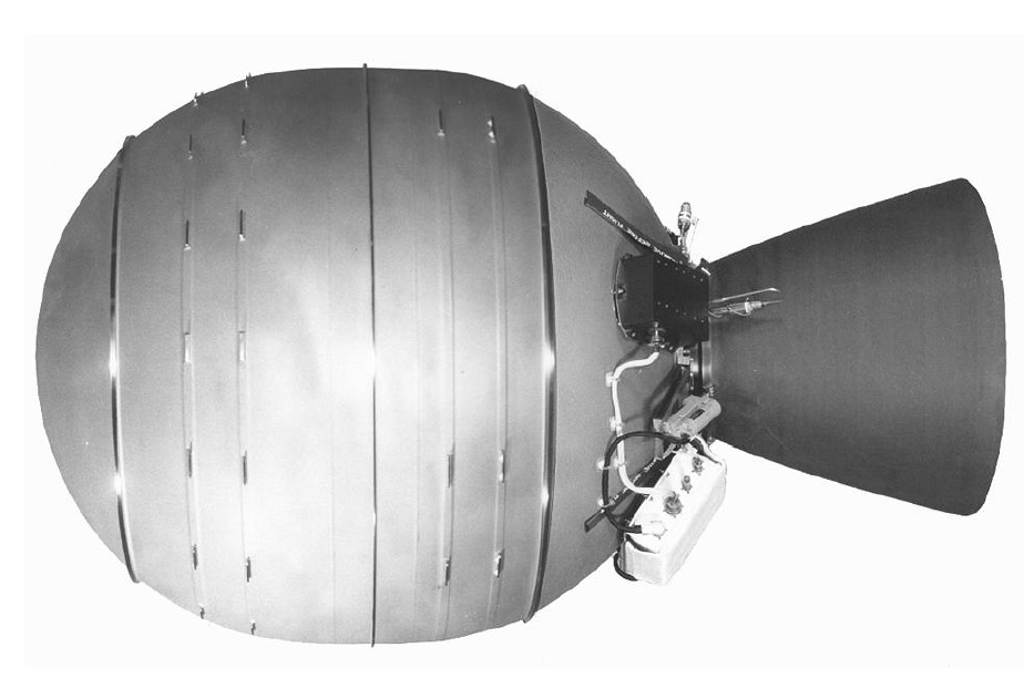
The Bi-Propellant Third Stage, BTS, is provided by Orbital Sciences and is based on Orbital’s GEOStar satellite bus that is used for Geostationary Satellites. The Upper Stage features a Helium-regulated bi-propellant system with Monomethylhydrazine fuel and Nitrogen Tetroxide oxidizer.
The propellants are stored in spherical tanks. A total of 358 Kilograms of MMH and 322 Kilograms of NTO can be carried by the vehicle. The propulsion system consists of three IHI BT-4 engines. BT-4 was developed by IHI Aerospace, Japan, and has a dry mass of 4 kilograms and a length of 0.65 meters. The engine provides 450 Newtons of Thrust.
The BTS can perform precise insertions and multiple engine burns for orbit circularization. Sun Synchronous Missions of Antares would typically use this upper stage.
Payload Fairing
| Diameter | 3.94m |
| Length | 9.87m |
| Mass | 970kg |
| Separation | Ordnance, Frangible Joints, Pistons |
| Construction | Aluminum Honeycomb |
| Graphite/Epoxy Sheets |
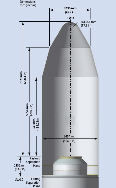
The Payload Fairing is positioned on top of the launch vehicle and its integrated Payload. It protects the spacecraft against aerodynamic, thermal and acoustic environments that the vehicle experiences during atmospheric flight.
When the launcher has left the atmosphere, the fairing is jettisoned by pyrotechnical initiated systems. Separating the fairing as early as possible increases launcher performance.
Antares jettisons its fairing during the Coast Phase between the first and second stage burn during a typical LEO Flight.
The fairing is 3.94 meters in diameter and 9.87 meters long. It consists of two composite shell halves, a low-shock frangible rail and ring separation system, and an actuator/hinge fairing jettison system.
The fairing structure is a aluminum honeycomb core covered by layers of graphic epoxy composite. The two fairing halves are joined by a frangible rail joint and the PLF is connected to the second stage using a ring-shaped frangible joint.
Ordnances and a clean-separation frangible joint with a confined sealed stainless steel tube is used to fracture aluminum extrusions on the ring and rail.
Disconnecting the ring and rail allows each half of the fairing to rotate on hinges installed on the second stage. A cold gas generation system is utilized to drive pistons that force the fairing halves to open..
Payload Adapters
Payload Adapters interface with the launch vehicle and the payload and are the only attachment point of the payload on the Launcher. They provide equipment needed for spacecraft separation and connections for communications between the Upper Stage and the Payload.
Orbital Sciences offers a number of standard payload adapters to install spacecraft on the Antares launch vehicle. Payload Adapters are provided by RUAG Space and include the 1194VS, 1666 and 937 payload systems that provide accommodations for a number of spacecraft and feature low-shock separation techniques
