
Proton Medium

Proton Medium is a variant of Russia’s Proton-M rocket jointly developed by its commercial operator, International Launch Services, and its manufacturer, the Khrunichev State Research and Production Center, with the goal of creating a more cost-efficient launch vehicle for medium-class communications satellites. Cost reduction is mainly achieved by eliminating the third stage from the Proton-M rocket which still allows the vehicle to lift over five metric tons into Geostationary Transfer Orbit at a cost expected to be competitive on the international launch market (especially looking at Falcon 9 as primary competitor).
The Proton Medium was presented in September 2016 in response to a growing demand for medium-lift launch capabilities as the commercial satellite sector slowly shifts from heavy satellites with only chemical propulsion to lighter craft outfitted with hybrid or all-electric propulsion systems.

All-electric and hybrid satellites have already gained a foothold on the commercial market and are likely to get more popular since they can be launched cheaper (due to their lower mass) and host more-powerful payloads as additional mass and volume (formerly taken up by chemical propellants) can be made available for the payload.
Launch services providers like Arianespace and their dual-payload launch architecture on Ariane 5 and ULA with their modular Atlas V/Vulcan can tailor their rockets or payload combination to respond to changing mass demands; SpaceX can offer competitive prices in part because of their re-usable design. Proton did not have any of these advantages and could only fly in one configuration, coming with a firm price tag.
The creation of Proton Medium was to optimize the vehicle for the cost-efficient launch of satellites in the three-to-five-metric-ton-range while keeping modifications to a minimum.
According to International Launch Services, Proton Medium can deliver 6.2 metric tons into a GTO-1800 orbit (requiring the spacecraft to provide 1,800m/s of delta-v to reach Geostationary Orbit), 5.5 metric tons into a GTO-1500 orbit and 2.8 metric tons directly into Geostationary Orbit.
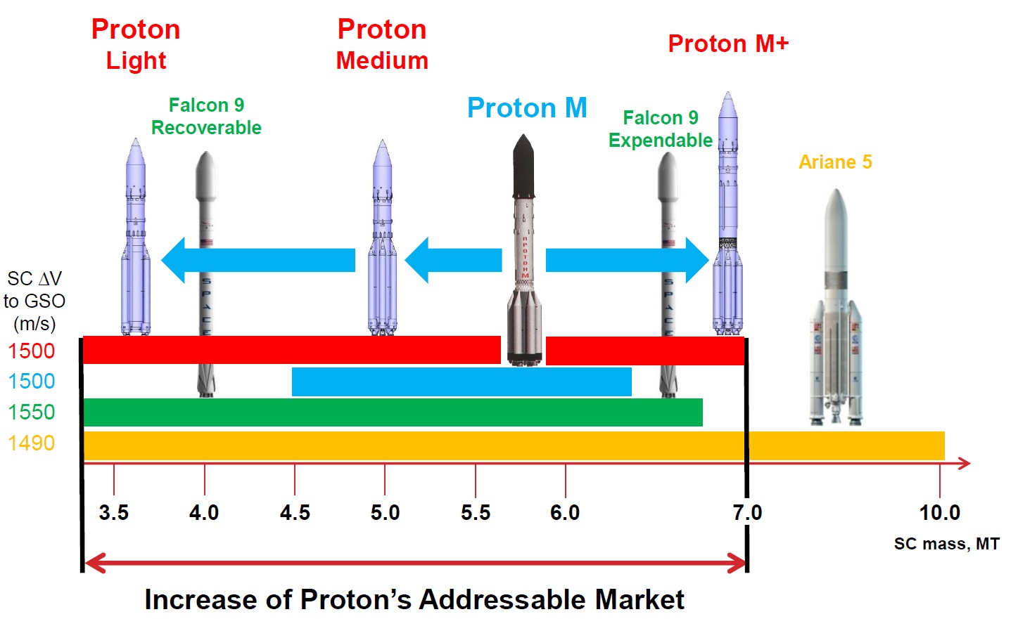
Proton Medium was envisioned to take on SpaceX’s Falcon 9, both in price and capability. Although SpaceX stated the Falcon 9 could lift up to 8.3 metric tons into a Geostationary Transfer Orbit, the vast majority of the satellites it had launched in 2016/17 weighed no more than 5.5 metric tons (with two notable exceptions). Lifting payloads of 5.5t and less allows Falcon 9 to recover its first stage, which will eventually come with fairly significant discounts for customers. Proton Medium – while fully expendable in all cases – will be able to match Falcon’s performance and is expected to be slightly more competitive with a launch price around $60 million whereas the 2017 starting price for a Falcon 9 GTO launch of <5.5t was $62 million.
One issue Proton Medium is facing is a less-than-optimal reputation of its big brother, the Proton-M, which had encountered failures and close calls on an annual basis between 2006 and 2016 including spectacular outright failures like the 2013 accident and close shaves like the 2016 engine-out scenario on the second stage. This left Proton in an undesirable situation where the insurance premiums for commercial payloads flying on it are three times higher than those for its competitors Ariane 5 and Falcon 9. (According to a 2017 article by Space Intel Report, the typical premium charged for a Proton-M mission was around 12% of the insured value vs. 3-4% for Ariane 5 and 4-5% for Falcon 9).
Proton’s launch manifest shrunk considerably in 2016-18 compared to the previous decade and re-gaining a customer base for Proton-M and Proton Medium may be a more difficult task for ILS than designing the new vehicle itself.
The Initial Plan: Proton Medium & Proton Light
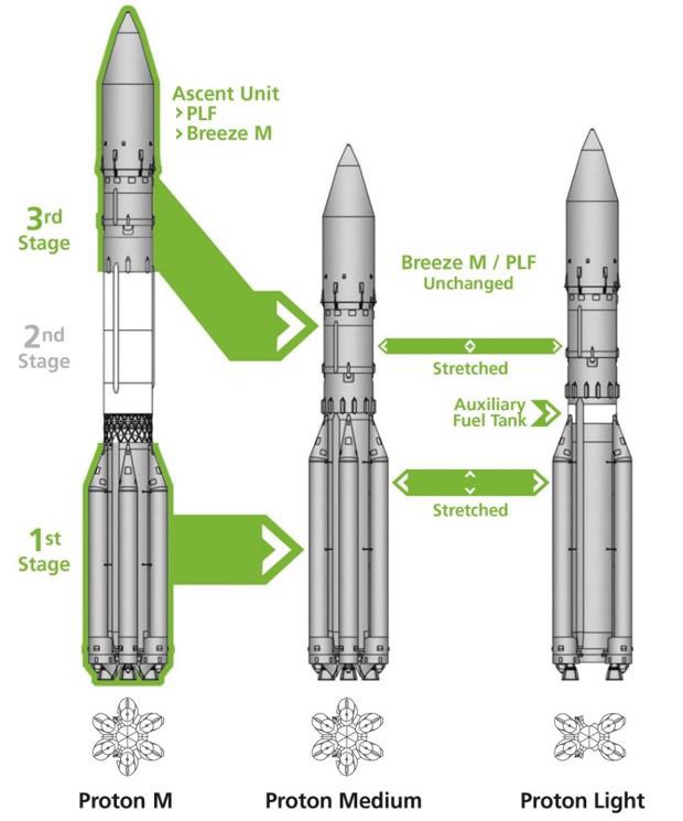
International Launch Services officially announced the “Proton Variants” on September 13, 2016, detailing two new launch vehicles to be created by downsizing the Proton-M rocket from a 3+1 to a 2+1 stage configuration.
Proton Medium was baselined for a GTO capability of five metric tons, tailored to heavy all-electric or typical hybrid satellites while Proton Light was conceptualized to deliver 3,600 kg to GTO to cover typical ell-electric and light hybrid birds. Additionally, both vehicles would have been useful for direct-to-GEO and Medium Earth Orbit Missions for which Proton-M is slightly oversized.
While ILS outlined their desire to create an optimized launch vehicle retaining the extensive heritage of Proton, it became clear that a number of modifications were needed to make “Proton Variants” a reality:
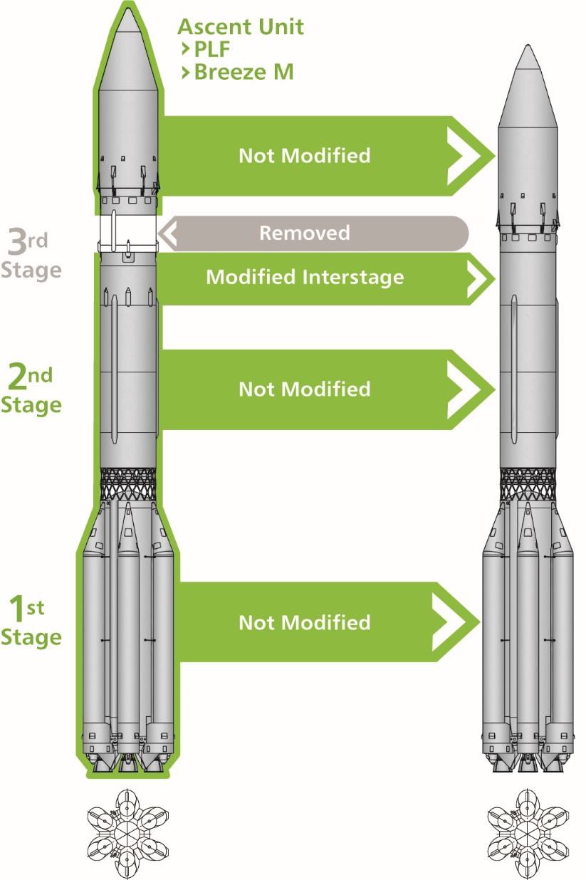
The primary modification from Proton-M to the two proposed variants was the removal of the second stage from the baseline Proton to eliminate a large chunk of its manufacturing cost. However, simply strapping a Proton-M first and third stage together via a newly developed interstage would not yield the desired performance of the Proton Medium which prompted additional modifications.
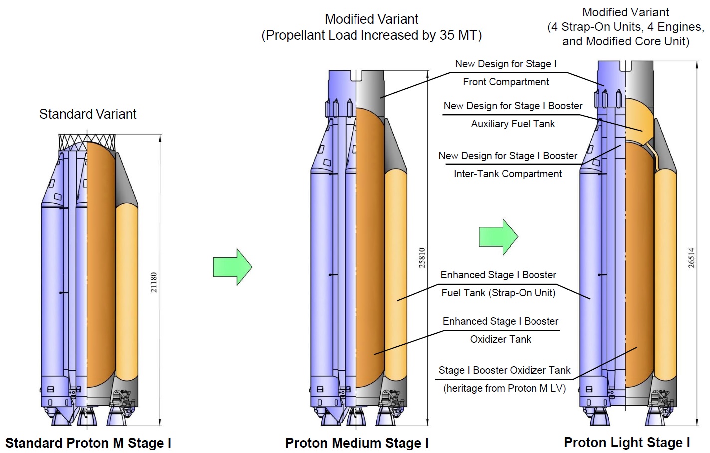
The first stage of Proton Medium was to have its core oxidizer tank and the six strap-on fuel tanks extended to hold 35 metric tons of additional propellant (an 8% increase) to achieve the desired staging velocity. In combination with the modified interstage, connecting the first stage with the former Proton-M third stage, the first stage would have grown from 21.18 to 25.81 meters
Naturally, with a vehicle that is lighter overall while carrying a larger prop load on Stage 1, Proton Medium would require a first stage drop zone located further downrange than the Proton-M. An advantage gained through the higher staging velocity was a lesser degree of contamination at the first stage impact site due to higher aerodynamic forces occurring at re-entry to break apart the structure and disperse/incinerate leftover Hydrazine and Nitrogen Tetroxide propellants which have been a major environmental concern associated with Proton’s core stage.
The interstage developed to connect the modified stages was to replace the lattice structure of the former Proton 1-2 interface with a composite interstage facilitating the large vacuum-expanded nozzle of the RD-0213 main engine. Cut-outs in the structure were to provide openings for the plumes of the four-chamber RD-0214 steering engine that fires before stage separation to assist in the separation and keep the Stage 3 propellants settled in the tanks.
Additional solid-fueled retrorockets retained from the original Proton-M Stage 1 adapter were to provide an additional push to discard the first stage and interstage adapter.
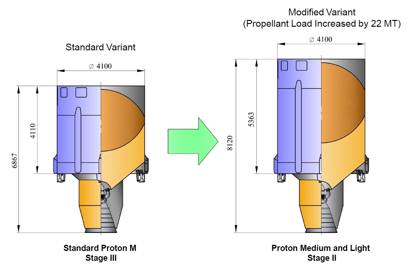
Sitting atop the newly developed interstage adapter was to be a stretched version of the Proton-M third stage, increasing in length from 6.87 to 8.12 meters and holding 22 metric tons of additional propellant (a 32% increase in propellant mass). Above the third stage would have been the standard Proton-M Ascent Unit comprising the payload fairing, Briz-M upper stage and the payload.
Proton Light imposed additional modification needs with respect to the first stage as the plan called for two of the six RD-275M main engines to be removed along with their associated external fuel tanks. Inside the first stage, the oxidizer was to be shortened and an Auxiliary Fuel Tank was to be added atop – causing the overall length of the first stage to grow to 26.51 meters. The second stage was not modified from Proton Medium to Proton Light.
From a logical sense, the plan to create a cost-efficient launch vehicle when introducing three different first stage specifications for the Proton-M, Proton Medium and Proton Light appeared less than optimal.
An additional problem emerged when looking at the Baikonur Cosmodrome’s ground infrastructure which would have needed extensive modifications to deal with the different vehicle dimensions (overall shortening of the rocket’s height but stretching of the first stage). This would have required additional crew access platforms to be installed on the Mobile Service Gantry of the Site 81/24 launch pad to allow workers to access the payload fairing section leading up to launch. Additional problems arose from the size of the existing railway trailers for transporting the Proton stages from Moscow to Baikonur which would not have been able to fit the extended stages.
The revised Plan: Back to the Roots with Proton Medium
After the September 2016 announcement, International Launch Services had lined out a plan to continue design studies into 2017 to evaluate the finer points of the design of the Proton Variants. According to Russian officials, the plan was all but set in stone and, by the time of the initial announcement, there had been several potential designs for a Proton Medium variant meeting the desired performance. This was also evident in Roscosmos design drawings coming out around the same time of the announcement showing Proton Medium & Light with identical first stage lengths.
By March 3, 2017, the “Proton Variants” had made quite some dramatic changes: Proton Light was quietly retired as a paper rocket (at least for the time being), Proton Medium was now to eliminate the Proton-M third stage and fly in a configuration resembling the original two-stage Proton, and ILS announced a new five-meter payload fairing to enable Proton-M and Proton Medium to lift sizeable satellites and multi-payload clusters for large constellations.
This approach to Proton Medium significantly lessened the amount of modifications and new hardware needed to get from Proton-M to Proton Medium while retaining the performance of the original concept presented in 2016. In essence, Proton Medium was to keep the 1-2 stack of the current Proton, fit it with a modified interstage and top it with an unchanged Ascent Unit – reducing re-design work to the interstage and modification of the flight profile including a new partial thrust flight mode on the second stage to keep accelerations in check.
The revised Proton Medium design takes Proton back to its roots: A two-stage Proton launched for the first as a space launch vehicle in 1965 after starting out as UR-500 Super-Heavy ICBM which turned out to be hopelessly oversized for a ballistic missile but just right for a role in heavy-lift space missions.
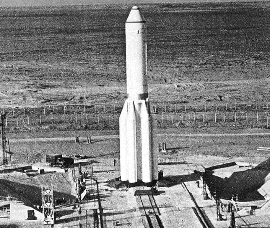
Back then, Proton stood 46.3 meters tall (warhead version) with a launch mass of 620 metric tons, powered by six RD-253 engines on its first stage and a pack of three RD-0208 and one RD-0209 on its second stage. After four test launches of the two-stage configuration came the three-stage Proton-K which introduced the RD-0212-powered third stage which has been a standard component of Proton ever since.
The revision of the Proton Medium design to use unchanged first and second stages will also allow production cost to be kept at a minimum without the requirement of building any stretched tankage. Concerns associated with the transportation of stretched stages were also alleviated and the extended Stage 2 – Briz-M interstage has also been specifically designed to keep the modifications needed on the Baikonur ground infrastructure to a minimum.
The elimination of the third instead of the second stage will cause the per-unit cost of Proton Medium to increase compared to the 2016 incarnation of the vehicle. However, the overall development cost will be lower due to the increased commonality with Proton-M which also made the endeavor more realistic to be completed in the time frame outlined for the development effort.

One large element of work completed in 2017 was the introduction of the five-meter Proton fairing in response to customer demand. According to ILS, the five-meter fairing is being commissioned to “address the increased volume of today’s larger satellites required to satisfy High-Throughput Satellite (HTS) broadband capacity demands, stacked satellite height requirements, and supports multiple satellites for efficient deployment of large LEO constellations.”
The latter was a primary driver in opting for a larger fairing: most GEO communications satellites, even those with large appendages, easily fit into Proton’s existing 4.35-meter fairing but multi-payload constellation missions typically employ cylindrical adapters around which the satellites are installed – creating a very wide payload assembly as the cylindrical dispenser must be sized to facilitate a certain number of satellites around its circumference (e.g. four satellites per tier for Iridium or eight for OneWeb).
Proton Medium Specifications
| Type | Proton Medium |
| Height | 55.44 m |
| Diameter | 7.4 m |
| Launch Mass | Approx. 648,000 kg |
| Stages | 2 + Briz-M Upper Stage |
| Boosters | None |
| Mass to GTO-1800 | 6,168 kg |
| Mass to GTO-1500 | 5,465 kg |
| Mass to GEO | 2,800 kg |
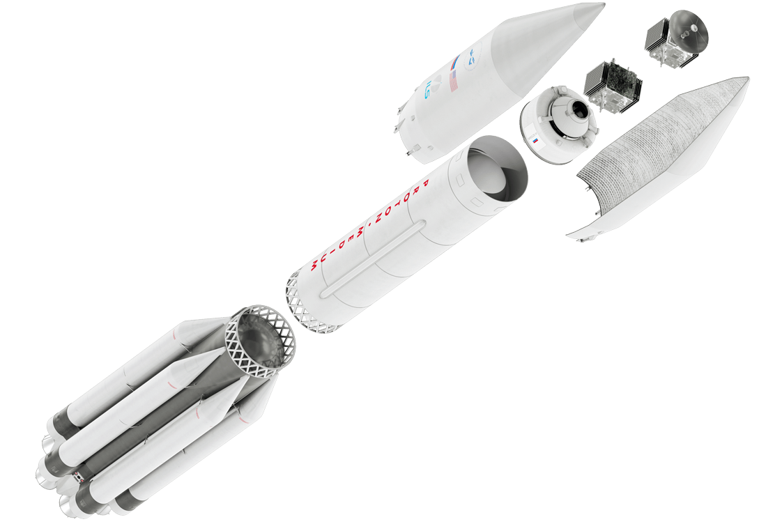
Proton Medium is a 2+1-stage derivative of the Proton-M 3+1-stage launch vehicle that eliminates the Proton third stage to create a more cost-effective vehicle for the launch of commercial satellites in the five-metric-ton range to remain competitive on the global launch market. In essence, Proton Medium retains the first and second stage stack of Proton-M in its entirety and fits it with a newly designed metallic interstage that interfaces with the Ascent Unit comprising the Briz-M upper stage, payload fairing and spacecraft.
Proton Medium stands 55.44 meters tall (2.74 meters shorter than Proton-M), has a span of 7.4 meters and weighs around 643 metric tons at liftoff without its payload (mass estimated from known characteristics of Proton-M). According to International Launch Services, the Proton Medium can lift 6.2 metric tons into a GTO-1800 Geostationary Transfer Orbit, 5.5 metric tons into GTO-1500 and 2.8 metric tons directly into Geostationary Orbit. This range is suitable for typical hybrid and heavy all-electric satellites that complete the transition to GEO through their own engines.
One of the largest changes to the rocket’s flight profile is a partial thrust mode on the second stage toward the end of its burn, accomplished by shutting down one of its four engines since the hypergolic-fueled engines lack a throttle capability.
First Stage
| Type | Proton-M Stage 1 |
| Inert Mass | ~31,000kg |
| Diameter | 7.4 m |
| Length | 21.18 m |
| Structure | Aluminum Alloy (AlMg6) |
| Propellant | Unsymmetrical Dimethylhydrazine |
| Oxidizer | Dinitrogen Tetroxide |
| Propellant Mass | 419,400kg |
| Guidance | From second Stage |
| Propulsion | 6 x RD-275M |
| RD-275M Thrust SL | 1,670 kN |
| RD-275M Thrust Vac | 1,830 kN |
| Specific Impulse (SL) | 288 sec |
| Specific Impulse (Vac) | 315.8 sec |
| Total SL Thrust | 10,020 kN |
| Total Vac Thrust | 10,980 kN |
| Engine Length | 3.00 m |
| Engine Diameter | 1.50 m |
| Engine Dry Weight | 1,120 kg |
| Throat Diameter | 279.7 mm |
| Combustion Chamber | 430.0 mm |
| Chamber Pressure | 165 bar |
| Ox. To Fuel Ratio | 2.67 |
| Expansion Ratio | 26.4 |
| Chamber/Nozzle Length | 2.23 m |
| Oxidizer Flowrate | 392.3 kg/sec |
| Fuel Flowrate | 146.9 kg/sec |
| Burn Time | 119.6 sec |
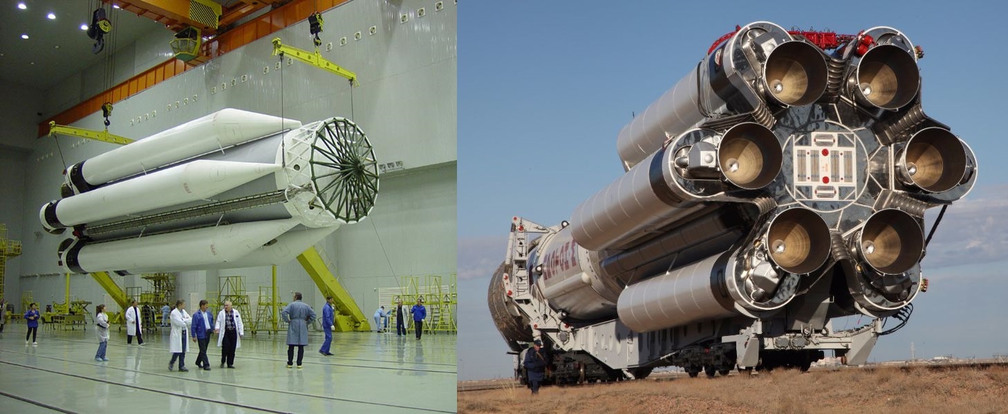
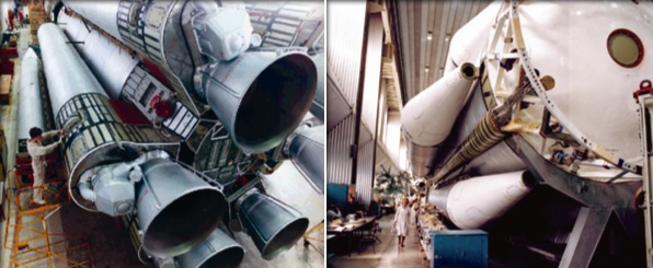
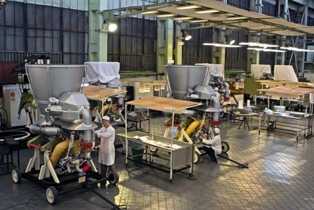
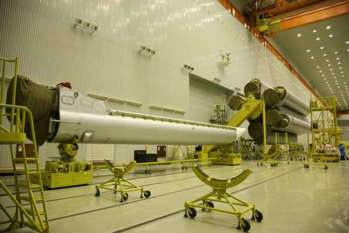
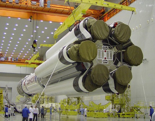
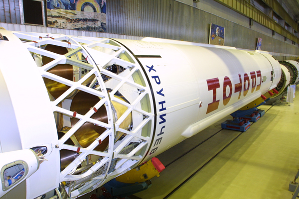
The first stage of the Proton Medium is identical to that of the Proton-M (Phase III/IV) launch vehicle which, in architecture, has been in operation since the first Proton launch in 1965 though has undergone modification over the years to be fitted with more-powerful engines and reduce its dry mass. It stands 21.18 meters tall and measures 7.4 in diameter, comprising a central oxidizer tank and six strap-on fuel tanks that give Proton its characteristic appearance.
The central oxidizer tank is 4.1 meters in diameter and each of the six external fuel tanks measures 1.6 meters in diameter and 19.86 meters in length with a tapered section on top to create an aerodynamic shape. The six fuel tanks resemble the appearance of strap-on boosters used on other rocket types but do not in fact separate from the first stage.
This sectioned design choice was made at the inception of Proton since the 4.1-meter core diameter was the largest possible for rail-transport to the Baikonur Cosmodrome. The fuel tanks are integrated with the core oxidizer tank at the launch site after separate delivery.
The fuel tanks build a critical structural element of the Proton launch vehicle as each hosts one of the six first stage main engines and is responsible for transferring loads to the central structure. There is no propellant cross feed between the six fuel tanks which deplete evenly as the engines burn and oxidizer is fed to the engines from the central core (the even depletion of all six fuel tanks is ensured by an RKS control system optimizing the mixture delivered to each engine to ensure an even burn).
The strap-on tanks attach to the core stage via five joints, two rigid joints at the base of the strap-on and three flexible joints that allow for some flexibility.
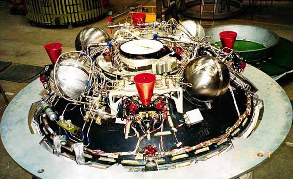
Proton’s first stage has dry mass of less than 31 metric tons and holds over 419 metric tons of Unsymmetrical Dimethylhydrazine fuel and Dinitrogen Tetroxide oxidizer, fed to six RD-275M engines.
One element of Proton’s evolution from the Proton-K (flown between 1967 to 2012) to the Proton-M (in service since 2001) and the Proton-M Phase upgrades was the reduction of the rocket’s dry mass through the use of lightweight composite material on the upper stage and modern-day milling techniques to reduce the mass of the vehicle’s tankage. As a result, Proton lost over 400 kg of weigh on its first stage alone.
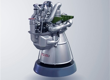
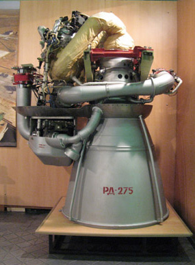
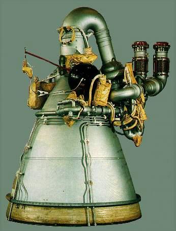
Built by NPO Energomash, the RD-275M – also known as RD-276, is an improved version of Proton’s original, Glushko-designed RD-253 engine and classed as the most-powerful single-chamber, hypergolic-fueled engine built in Russia. RD-253 (1,470kN SL thrust) served on the first four Proton missions in 1965/66 that used the two-stage configuration and it continued to power the vehicle as it upgraded to the three-stage Proton-K.
An initial performance enhancement on the RD-253 was realized by increasing the propellant mass flow by slight modifications of the propellant flow control valves after it had become clear that most structural margins on the engine would permit a 7.7% thrust increase with structural reinforcements made only on the gas generator and combustion chamber. This enhancement first flew as a mission-unique feature on the 1986 and 1987 launches of the Core and Kvant Modules of the Mir Space Station (RD-253F).
Qualification of this engine version, known under the operational designation RD-275 (1,590kN SL) was completed between 1987 and 1993 and the engine began flying as a standard feature on Proton-K in 1995. RD-253 was retired in 1997 after supporting 250 Proton launches and the introduction of RD-275 provided a 600-Kilogram increase in Proton’s GEO capacity.
The second round of improvements on the RD-275 engine started in 2001 to obtain another thrust boost of 5.2% by further increasing the engine’s operating pressure by 8.3 bar. Testing of the RD-275M engine wrapped up in 2005 and it began operations on Proton-M in 2007, yielding another 150-Kilogram increase in GEO performance.
Like many Russian engine developments, the RD-275M operates an oxidizer-rich, staged combustion cycle which, compared to fuel-rich alternatives, offers higher performance but creates a more-challenging environment due to the temperature and corrosive properties of the oxidizer-rich mixture in the engine. Additional performance is gained through the use of a closed cycle in which the entire propellant flow into the engine is brought to combustion and no low-pressure turbine exhaust is dumped overboard.
The RD-275M engine stands 3.05 meters tall and is 1.50 meters in diameter with a dry mass of 1,070 kilograms and a flooded mass of around 1,250 kg. It delivers a sea level thrust of 1,670 Kilonewtons, climbing to 1,830 kN in vacuum with corresponding specific impulses of 288 and 315.8 seconds. The engine operates at a chamber pressure of 165 bar, feeding a 26.2-expanded nozzle.
RD-275M employs a single, gas-generator-driven turbine for powering the engine’s turbopumps – a single-stage oxidizer pump and a two-stage fuel pump, both arranged on a single axis but employing different drive shafts connected with a spring assembly to transfer the torque from the oxidizer pump shaft to the two-stage fuel pump. The entire oxidizer flow passing through the turbopump is injected into the gas generator while the output from the first stage of the fuel pump is divided in two with one portion flowing into the regenerative cooling cycle and the other directed into the second-stage fuel pump which creates the required pressure and flow rate for the gas generator.
The gas generator operates at an oxidizer-to-fuel ratio of 21.5 to create a turbine power in excess of 26,000 horsepower to drive the two turbopumps at over 14,000 RPM for the oxidizer. The 785-Kelvin oxidizer-rich gas from the turbine is routed into the combustion chamber where it is combined with the fuel flow from the chamber & nozzle cooling cycle to be fully combusted at a mixture ratio of 2.67.
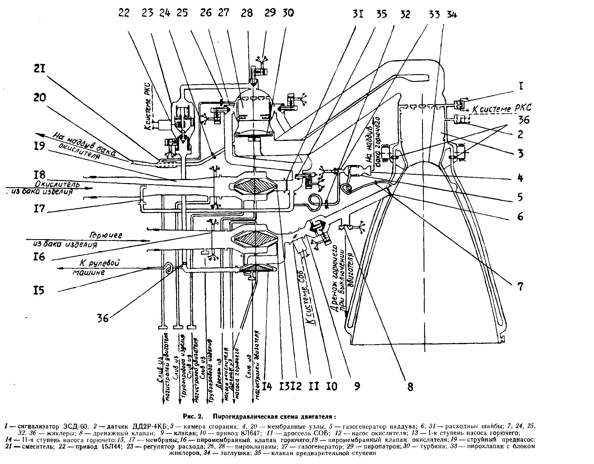
Engine start is a carefully controlled process that involves the sequential opening of a series of engine valves to put the engine into steady-state operation. Because self-igniting propellants are used, no igniters are necessary, but particular attention has to be paid to avoid bleed-in of fuel into the oxidizer system and vice versa within the turbopump assembly.
Pyrotechnic valves (employing a pyrotechnic cutting mechanism to cut open a membrane) fire 0.7 seconds after the engine ignition command is given to allow the engine plumbing to fill with propellant components under the hydrostatic pressure created by the propellant tanks. This allows propellant to flow through the pumps and into the gas-generator where the two components are mixed through 85 fuel and 288 oxidizer injector nozzles and combust upon contact to begin driving the turbine. The gas generator operates in a two-zone scheme with 70% of the oxidizer flow passing through the injectors while the rest is routed through heat exchangers in the GG mantle and then being injected around the flow of heated product gas to provide a thermal boundary between the hot zone where combustion occurs and the GG housing.
Once combustion begins in the main chamber, a membrane protecting the injectors /chamber during storage on the ground is broken and ejected from the nozzle.
During the ignition phase, fuel flow to the gas generator is limited by a dedicated flow regulator. As pressures increase, membranes are broken to allow propellants into the tank pressurization and gimbal systems to prepare them for steady-state operation. Around 1.8 seconds after ignition command, the engine controller commands the gas generator fuel flow regulator to fully open to allow the turbine to spin up to flight speed.
Proton lifts off once engine thrust exceeds the rocket’s mass; there is no hold-down system. The engines reach their full thrust level shortly after liftoff and are kept at operational conditions through a feedback loop that employs twofold sensing system: a pressure sensor in the main combustion chamber provides feedback on the operation of the engine (to be kept within an operational pressure band) while the rocket’s guidance system tracks the vehicle’s speed vs. the prediction to fine tune the thrust level according to the flight trajectory.
This regulation is achieved by the fuel flow regulator to the gas generator which speeds up/slows down the turbopumps by means of fuel flow into the gas generator based on commands from the engine controller.
The mixture ratio of fuel and oxidizer is controlled by flow restrictors in the main propellant lines after the turbopumps and an additional fuel trim system after the first-stage pump is employed for fine control to ensure the tanks empty at the same rate by controlling the fuel flow into the main combustion chamber.
Shutdown of the engine is also a multi-stage process to prevent pressure hammering from destroying the engine. The first step is the closure of the gas generator fuel inlet pyrovalve and the oxidizer tank pressurization pyrovalve which will cause the gas generator to be starved of fuel to stop the combustion process while oxidizer still flows through from the residual tank pressurization and pump rotation. Fuel is also still allowed into the main combustion chamber through the regenerative cooling loop.
The second shutdown stage is accomplished over 0.2 seconds by closing oxidizer valves to the gas generator and the main fuel valve to the combustion chamber. This ends propellant flow through the gas generator, main chamber and mixers for tank pressurization and gimbaling. A propellant dump valve then opens between regen cooling cycle and the cutoff valve to allow fuel still in the cooling system to escape at low pressure to avoid residual thrust on the engine (the dump valve remains closed in case of an aborted ignition on the ground, the rest of the shutdown process remains the same).
The combustion chamber and nozzle of the RD-275M engine stand 2.24 meters tall and weigh around 435 Kilograms. The combustion chamber is 430 millimeters in diameter and closes into an engine throat diameter of 279.7 millimeters which then broadens to a nozzle exit diameter of 1.43 meters.
A jet pre-pump before the oxidizer inlet provides an increase in static pressure at the inlet to ensure the engine can operate at low oxidizer tank pressures without cavitation in the main pump. Tank pressurization is accomplished with a gas generator on the fuel side and a mixing unit on the oxidizer side.

The gas generator is fed from a tapoff line on the oxidizer turbopump outlet and the fuel line from the inlet of the generative cooling cycle; flow restrictors act as regulation devices to achieve a simplified architecture. It operates at a mixture ratio of 0.06 and, like the main GG, employs a two-zone scheme where all of the oxidizer inflow and a third of the fuel flow is brought to combustion while the rest of the fuel is used to create a cooling film on the inside of the enclosure. The gas generator delivers an outlet pressure of 25 bar which is fed to the fuel tank the respective engine is attached to.
The oxidizer pressurization mixer is fed with oxidizer-rich tapoff gas from the turbine which is mixed with oxidizer flow from the gas generator inlet to cool the gas. It delivers an outlet pressure of 35 bar fed through a pressurization line to the central oxidizer tank which is kept at pressure by all six engines.
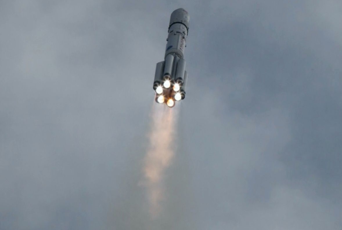
Proton uses a one-degree of freedom thrust vector control system on its first stage. Each of the six engines can only move +/-7 degrees in one direction, tangentially to the circular engine cluster – enabling three-axis control through the collective gimbaling inputs of the engines. The one-axis gimbaling system is driven by a hydraulic system supplied by a tapoff line from the second-stage fuel pump.
A crude form of thrust vector control employed during the initial roll maneuver after liftoff is differential thrust vector control achieved by reducing thrust on one engine by limiting propellant flow into its combustion chamber (visible as the dim engine near the six-o-clock position in the image).
The first stage of the Proton Medium fires for 119.6 seconds, accelerating the rocket to a staging velocity of 2.18 Kilometers per second (vs. 1.72 km/s for Proton-M) and dropping away at an altitude of 50 Kilometers. A consequence of the elimination of the third stage from the rocket is a much higher staging velocity which will cause the first stage to travel further downrange, impacting 492 Kilometers from the launch pad (vs. 310 km for Proton-M).
Second Stage
| Type | Modified Proton-M Stage 2 |
| Inert Mass | ~11,900 kg |
| Diameter | 4.1 m |
| Length | 18.43 m |
| Structure | Aluminum Alloy |
| Propellant | Unsymmetrical Dimethylhydrazine |
| Oxidizer | Dinitrogen Tetroxide |
| Propellant Mass | 156,113 kg |
| Guidance | Inertial |
| Propulsion | 3 x RD-0210, 1 x RD-0211 |
| RD-0210 Thrust Vac | 582 kN |
| Specific Impulse (Vac) | 326.5 sec |
| Total Vac Thrust | 2,328 kN |
| Engine Length | 2.33 m |
| Engine Diameter | 1.47 m |
| Engine Dry Weight | 566 kg |
| Throat Diameter | 163 mm |
| Combustion Chamber | 276 mm |
| Chamber Pressure | 147 bar |
| Ox. To Fuel Ratio | 2.6 |
| Expansion Ratio | 28.5 |
| Chamber/Nozzle Length | 1.67 m |
| Oxidizer Flowrate | 131.3 kg/sec |
| Fuel Flowrate | 50.5 kg/sec |
| Burn Time | 210.8 sec |
The second stage of Proton Medium is identical to the second stage used on the Proton-M rocket with the exception of the interstage that connects the stage with the Ascent Unit Sitting atop whereas on Proton-M, the adapter is shorter and interfaces with the third stage. Another change from the Proton-M to Proton Medium does not manifest in hardware but a different flight profile of the second stage with a partial engine shutdown toward the end of its burn to limit longitudinal acceleration on the ascending launch vehicle.
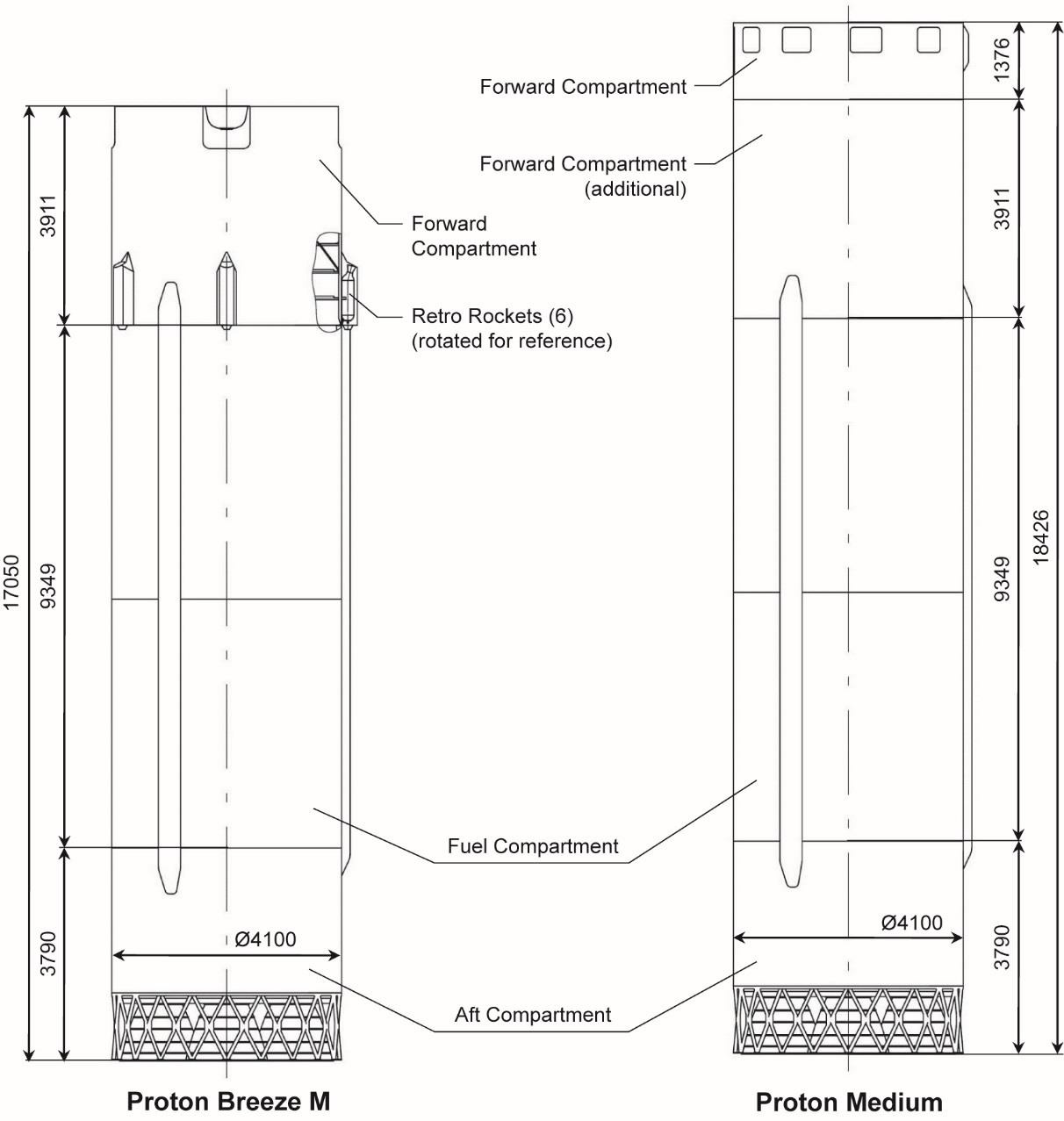
Unlike the first stage, Proton’s second stage uses the conventional cylindrical design with the fuel and oxidizer tanks mounted in a stacked configuration within the stage. Its structure consists of an aft compartment housing the engines, a fuel compartment holding the propellant components and a forward compartment / forward compartment extension building the interface with the Ascent Unit.
The Proton Medium second stage shares the first stage’s 4.1-meter diameter and stands 18.43 meters tall (with interstage, 1.4 m taller than Proton-M’s second stage). It has a dry mass around 12 metric tons and holds 156,113 Kilograms of Unsymmetrical Dimethylhydrazine fuel and Dinitrogen Tetroxide oxidizer. The oxidizer tank is located above the fuel tank and the oxidizer line to the engines runs through the center of the UDMH tank. A common bulkhead is used between the tanks as a mass and space-saving measure to optimally use the internal volume of the second stage.
The aft compartment of the second stage stands 3.79 meters tall and hosts the four second stage engines and the upper portion of the Stage 1-2 interstage structure. In addition to the engines and all their associated equipment, the aft section also houses six angular rate sensors that act as the primary attitude determination device on the second stage. The tank section of the second stage is 9.05 meters tall.
The major change on the second stage hardware from Proton-M to Proton Medium is the interstage adapter which received a 1.38-meter extension section sitting atop, creating a total forward compartment length of 5.29 meters. On Proton-M, the Stage 2 Interstage Adapter is fitted with six solid-fueled retrorockets to push the stage away from the third stage to assist in the hot-staging sequence. These are eliminated on Proton Medium since separation of the Briz-M upper stage is accomplished with springs and the Briz-M engines (retrofiring solids would also pose major contamination risk to the exposed payload).
Another requirement arising from the elimination of the Proton third stage was moving the Booster Avionics Bay, situated atop the stage, to the second stage to provide guidance for the two lower stages. The various boxes comprising the avionics assembly were thus moved to the forward compartment extension of the second stage.
However, this was not responsible for the lengthening of the interstage compartment which was driven by creating a vehicle height that would require the least modifications on the existing ground infrastructure at Baikonur with respect to the service tower and transporter-erector.
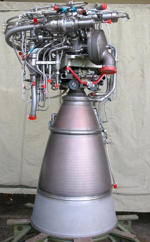
The second stage of the Proton rocket is powered by three RD-0210 and one RD-0211 engines which are identical in their propulsive function, generating 582 Kilonewtons of vacuum thrust, with the major difference being that RD-0211 is fitted with gas generators to provide pressurization gas to the tanks.
These engines, like those of the first stage, start out at the very dawn of the space age and have undergone significant upgrades since. Their development began in 1961 as RD-0203/0204 for the first stage of the UR-200 ballistic missile with a performance target of 500 kN per engine (SL). When Proton (back then known as UR-500) began development on the drawing board, its first stage was to host four RD-253 main engines and four RD-0203 engines for steering & additional thrust.
UR-200 was tested between 1963 and 65 and Proton’s design was revised in the same period – eliminating the engine from the first stage and moving it to the second stage – requiring an air-startable version to be developed. It differed from the original design mainly in the expansion of the nozzle to optimize the engines for operation in the tenuous layers of the atmosphere from 50 Kilometers up.
The RD-0208/0209 version of the engine, developed between 1962 and 66, operated at a chamber pressure of 147 bar and generated a vacuum thrust of 570 Kilonewtons. The upgrade was primarily focused on adding a membrane valve, cutoff and bypass into the fuel system to prevent the turbopumps from excessively spinning and ensure the gas generator ignition must occur before propellant components meet in the combustion chamber. A slight performance increase was achieved through the use of more effective turbopump injectors.
Almost concurrently with their development, KBKhA was also developing an upgraded version (1962-67) that was to power the Proton-K rocket and had the overall objective of extracting additional performance but mainly to increase the reliability of the engine through reinforcements of critical components like gas generator, turbine and combustion chamber. Operation on Proton-K also required the engines to be certified for up to 70 seconds of additional burn time.
Improvements of the RD-0210/0211 upgrade included the optimization of the oxidizer gas generator injectors to reduce vibration; a zirconium dioxide thermal protection coating was introduced on the internal surface of the combustion chamber. Reliability was also improved through strengthening of testing procedures – increasing the production batch size from five to six so that two of the engines could be test fired while four were cleared for integration on the launch vehicle; an additional step was testing the pressure integrity of flight engines through helium pressure decay checks.
The RD-0210/0211 engines have been flying on Proton since March 1967 and, over the years, have undergone some modernization with respect to manufacturing processes and materials used in weld and solder joints. The engine stands 2.33 meters tall, is 1.47 meters in diameter and weighs 566 Kilograms; it delivers a vacuum thrust of 582 Kilonewtons at a specific impulse of 326.5 seconds.
The RD-0210/0211 engines are strikingly similar to the RD-253/275 engines used on the first stage – sharing the same closed combustion cycle with oxygen-rich gas generator, single-shaft turbopump, regenerative cooling cycle for the chamber and nozzle (fuel), two-zone gas generator (oxidizer as coolant), and dual-feedback systems for engine control (fuel flow variation to the GG to keep engine pressures & temperature within bands; fuel flow variation through the regen cycle to control the even consumption of oxidizer and fuel). Changes from the RD-253 cycle lie in the use of boost pumps for both propellant components to prevent cavitation at low tank pressures
Another difference to the first stage engines is the ignition sequence of the RD-0210/0211 engines. Starting out as a first stage engine, they relied on a one-second long nitrogen purge prior to the ignition trigger followed by the injection of pressurized gas (air or nitrogen) from a ground system to get the turbine spinning and open the main fuel and oxidizer valves. To achieve an air-start capability outside the dense atmosphere, the engines have to bring the initial burst of gas pressure with them in the form of a small spherical gas tank.
All four engines of the second stage employ an electro-hydraulic, two-axis gimbal system, capable of moving each nozzle by 3.25 degrees to support three-axis control during the second stage flight phase.

Neither the RD-0210 nor the RD-0211 have a throttle capability which leads to a challenge for Proton Medium because their nominal thrust setting would overwhelm the typical acceleration tolerance of most satellites toward the end of the second stage burn (conventionally, all launch vehicles limit longitudinal acceleration to 5 Gs). To comply with the 5G upper limit, Proton Medium will employ a partial shutdown scheme on the second stage (not dissimilar to Saturn V’s inboard engine cutoff and Falcon 9 v1.0’s dual-shutdown in the late stages of first stage flight as their engines could also not throttle deep enough).
Proton Medium will be programmed to shut down one of the RD-0210 engines at T+313 seconds, just as the vehicle would accelerate through 4.9 Gs – reducing thrust on the second stage to 1.8 MN which will reduce acceleration back to 3.7 Gs. The vehicle will then fly on three engines – gimbaling to overcome the unsymmetrical thrust provided by the three-engine configuration. Shutdown of the second stage is expected at T+330.5 seconds at an altitude of 175 Kilometers and a speed of 7.20 Kilometers per second – delivering the Briz-M upper stage onto a sub-orbital trajectory.
Briz-M Upper Stage
| Type | Briz-M |
| Length | 2.61m |
| Diameter | 4.0m |
| Fuel | Unsymmetrical Dimethylhydrazine |
| Oxidizer | Nitrogen Tetroxide |
| Inert Mass | 2,370kg |
| Propellant Mass | 19,800kg |
| Launch Mass | 22,300kg |
| Propellant Tanks | Aluminum Alloy |
| Tank Pressurization | Helium |
| Propulsion | S5.98 |
| Engine Type | Gas Generator, Open Cycle |
| Thrust – Vacuum | 19.62kN |
| Specific Impulse Vac | 328.6s |
| Engine Diameter | 948mm |
| Engine Length | 1150mm |
| Engine Mass | 95kg |
| Mixture Ratio | 2.00 (+/-0.04) |
| Burn Time | Total: 3,200s, Single Burn: 2,000s |
| Chamber Pressure | 95-98bar |
| Restart Capability | Up to 8 |
| Settling Thrusters | 4 x 11D458M |
| Fuel | Unsymmetrical Dimethylhydrazine |
| Oxidizer | Nitrogen Tetroxide |
| Thrust | 392N |
| Specific Impulse | 296s |
| Thruster Length | 469mm |
| Thruster Diameter | 192mm |
| Thruster Mass | 3.0kg |
| Mixture Ratio | 1.85 |
| Inlet Pressure | 14.7bar |
| Min Impulse Bit | 13.7Ns |
| Burn Time | 0.05 to 1,000s |
| Cycle Life | 10,000 |
| Reaction Control | 12 x 17D58E |
| Fuel | Unsymmetrical Dimethylhydrazine |
| Oxidizer | Nitrogen Tetroxide |
| Thrust | 13.3N |
| Specific Impulse | 269s |
| Thruster Length | 140mm |
| Thruster Mass | 0.55kg |
| Mixture Ratio | 1.85 |
| Inlet Pressure | 7.8 to 34.4bar |
| Burn Time | 0.03 to 10,000s |
| Cycle Life | 450,000 |
Briz-M is a hypergolic upper stage developed for the Proton Rocket allowing access to a variety of orbits including Geostationary Transfer Orbit, Geosynchronous Orbit, escape trajectories and all types of lower orbits. Due to its propellant combination and low-performance engine, the payload capacity of Proton with Briz-M is much smaller than with Block-DM semi-cryo upper stage.
Briz was developed on the basis of an anti-satellite propulsion system studied in the 1980s and first flew as Briz-K before being developed into the smaller Briz-KM for the Rockot launcher and its larger sister, the Briz-M, for Proton missions. Briz-M first flew in 1999 and the KM version made its debut in 2000.
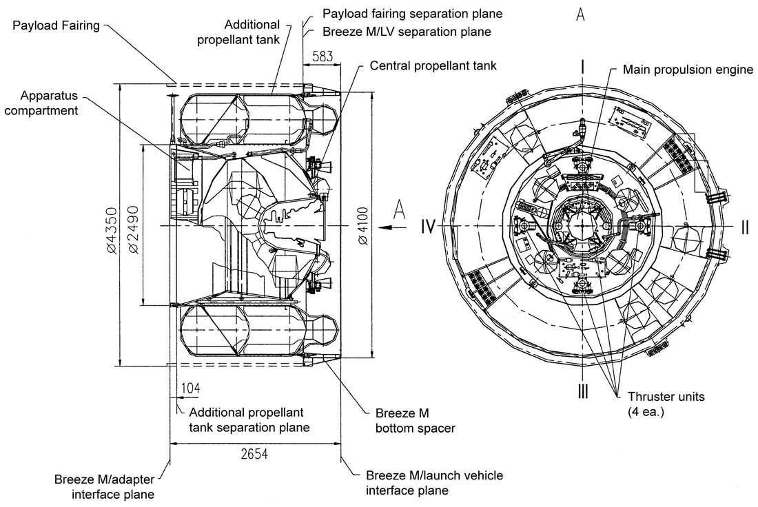
Briz-M is 4.0 meters in diameter and 2.61 meters in length consisting of a central block that houses propellant tanks, the engine compartment, pressurization systems and the flight control system. The Core Section is 2.49 meters in diameter. A toroidal tank section installed around the core vehicle carries additional propellants and is jettisoned after being emptied. In total, Briz-M weighs around 22,300 Kilograms including 5.2 metric tons of propellants stored in the core module and 14.6 tons of propellants carried in the Auxiliary Propellant Tank.
The Central block consists of an oxidizer tank on top of the fuel tank, both are separated by a common bulkhead. The tanks include hydraulic and pneumatic systems as well as internal baffles to prevent propellant sloshing inside the tanks. Structurally, the tanks are toroidal in shape, leaving a cavity at the bottom to provide space for the main propulsion system in order to minimize the length of the stage. Below the tanks, the engine compartment features the main propulsion system, settling and attitude control thrusters, spherical helium pressurant tanks and spherical high-pressure propellant tanks for the settling and attitude control systems. The tanks are coated with screen vacuum thermal insulation to avoid excessive cooling of the propellants that affects viscosity and can lead to freezing the lines and tanks.
On top of the Central Block is the equipment section of the Briz-M that is housed in an inverted truncated cone that features sub-frames to provide installation surfaces for the various controllers, telemetry modules, batteries and communications systems. Installed on the top frame of the Central Block is the payload adapter that provides the structural attachment point of the spacecraft and also includes communication interfaces. Payload adapters up to 2.49 meters in diameter can be supported.
At the bottom of the Central Block is a 60-centimeter long adapter section that builds the structural interface between the Briz-M and the second stage of the launch vehicle and also provides attachment points for the payload fairing to transfer loads from the fairing and house separation equipment. This interstage section is separated with the second stage. Briz-M is encapsulated in the payload fairing of the launcher and reduces the available payload envelope.
The Auxiliary Propellant Tank is mounted to the Central Block via a number of structural struts. Umbilical Interfaces are used to transfer propellants, power, and data between the two components. The toroidal compartment with cylindrical shells is divided into two separate tanks by an intermediate bulkhead creating an oxidizer tank (top) and fuel tank (bottom). Loads from the vehicle are transferred to the APT via the load-bearing cone inside the oxidizer tank and the outer cylindrical shell of the fuel tank. The tanks also include baffles to dampen propellant sloshing.
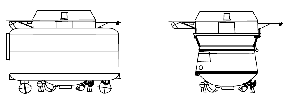
Once the 14.6 metric tons of hypergolics inside the APT are consumed, the tank section is jettisoned by initiating pyrotechnic bolts that cut the structural attachment points of the APT. Electrical and fluid connectors automatically disconnect at separation and spring pushers initiate the clean separation of the APT that is ensured by guide rails and roller supports on the tank and Central Block.
Briz-M includes two propellant systems – one low-pressure system for the main engine and a high-pressure system for the settling thrusters and the attitude control system. Both use Unsymmetrical Dimethylhydrazine as fuel and Nitrogen Tetroxide as oxidizer. These hypergolic propellants ignite immediately when coming into contact.
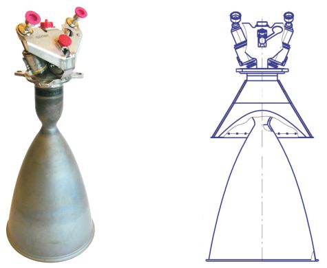
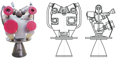
Briz-M uses a single S5.98 main engine that delivers 19.62 Kilonewtons of thrust (2,000kgf) and is based on an open cycle design. In this propulsion scheme, a small amount of oxidizer and fuel are injected into a gas generator that creates a high-pressure hot gas consisting of combustion products. This high-pressure gas feed is used to drive the turbines of the turbopumps of the fuel and oxidizer to deliver high-pressure propellant components into the combustion chamber. Regenerative cooling is accomplished by flowing propellant through the engine heat exchangers that cool the combustion chamber and warm up the propellants to temperatures where they have favorable physical properties.
S5.98 operates at a chamber pressure of 95 to 98 bar and uses a propellant mixture ratio of 1.96 to 2.04. It generates a specific impulse of 328.6 seconds. Overall, the engine is 115 centimeters long and 94.8 centimeters in diameter weighing 95 Kilograms. S5.98 can support up to eight re-starts in flight.
S5.98 is protected by a cover that is opened for main engine burns and protects the engine during coast phases using a hinged opening mechanism.
The propellant settling system is comprised of four 11D458M thrusters installed on four thruster pods located on the aft end of the Central Block. These pods include one settling thruster and three attitude control engines connected to the same propellant supply. Also consuming hypergolic propellants, the settling and attitude thrusters use propellants supplied by the high-pressure system.
Each settling thruster delivers 392 Newtons of thrust being 46.9 centimeters long and 19.2 centimeters in diameter with a mass of about 3 Kilograms. 11D458M operates at a mixture ratio of 1.85 and a propellant inlet pressure of 14.7 bar. It can be fired in pulse mode or make long steady-state burns and is certified for firings of up to 1,000 seconds and 10,000 duty cycles. For propellant settling, all four thrusters are activated 15 seconds before the main engine start to provide a forward acceleration for propellant settling inside the large tanks.
The attitude control thrusters used on Briz-M are known as 17D58E providing a nominal thrust of 13.3 Newtons. Each unit is 14 centimeters long and weighs 550 grams. The thruster also operates at a mixture ratio of 1.85 and a nominal inlet pressure of 14.7 bar, but it can tolerate a large pressure range from 7.8 to 34.3 bar. For attitude control, the thrusters are used in pulse mode with a minimum on-time of 0.03 seconds, but 17D58E is also certified for burns in steady-state mode up to 10,000 seconds. The engine is certified for 450,000 duty cycles.
Briz-M is outfitted with an inertial guidance platform, a digital flight computer and batteries that allow the stage to operate for up to 24 hours.
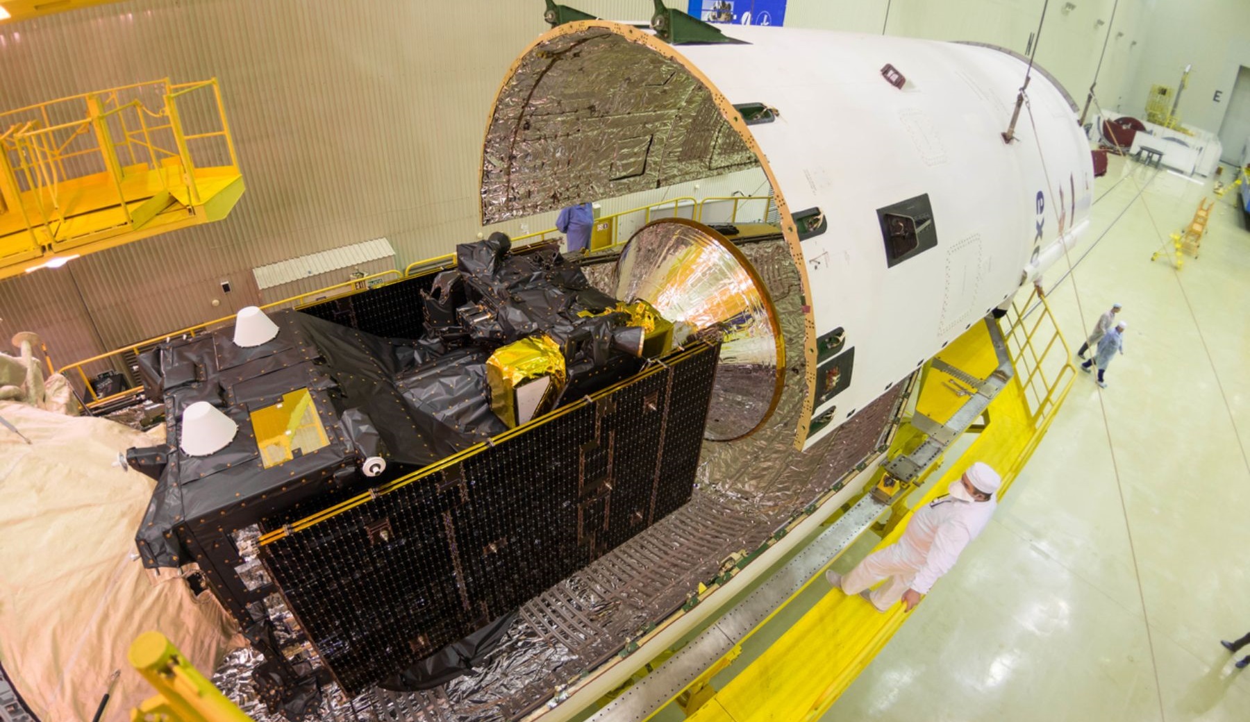
Payload Fairing
| Type | Standard Proton Fairing |
| Diameter | 4.35 m |
| Length | 13.31 / 15.26 m |
| Mass | ~2,000 kg |
| Type | Large Proton Fairing |
| Diameter | 5.2 m |
| Length | 17.80 m |
| Introduction | 2020 |
The Proton Medium launch vehicle will support the standard Proton-M payload fairing range, covering two 4.35-meter diameter fairings, and the planned 5.2-meter payload fairing to be introduced in 2020 across the Proton fleet.
On Proton Medium, the payload fairing interfaces with the metallic interstage atop the second stage and houses the Briz-M and the payload stack.
The baseline Proton payload fairings have an outer diameter of 4.35 meters and a usable payload volume 3.87 meters in diameter. The standard fairing is 13.31 meters long while the extended version measures 15.26 meters in length, corresponding to cylindrical payload envelope heights of 3.95 and 6.07 meters before the fairing narrows toward its tip.
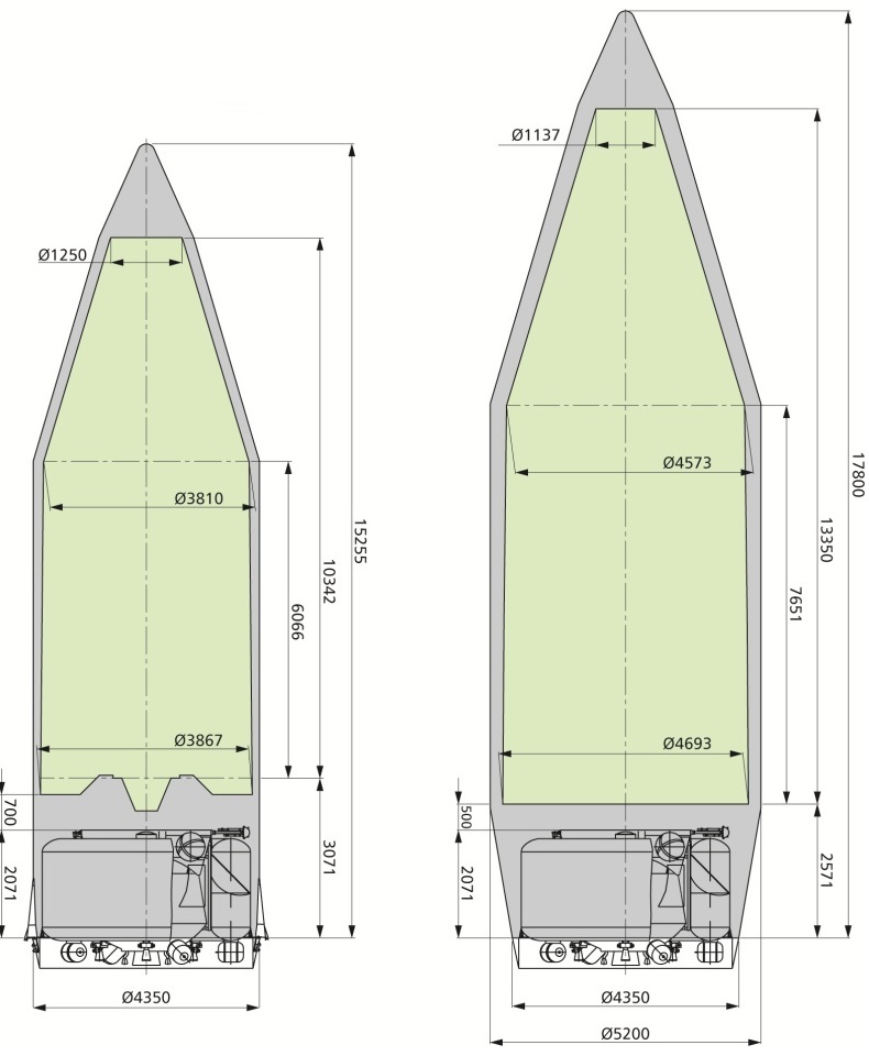
International Launch Services announced the addition of the 5.2-meter fairing in 2017, citing customer demand for a larger fairing diameter, especially in the area of multi-payload deliveries for large satellite constellations which require a large envelope diameter to fit their cylindrical payload dispensers with the satellites attached on their outside.
Most GEO communications satellites, even those with large appendages, easily fit into Proton’s existing 4.35-meter fairing but multi-payload constellation missions typically employ cylindrical adapters around which the satellites are installed – creating a very wide payload assembly as the cylindrical dispenser must be sized to facilitate a certain number of satellites around its circumference (e.g. four satellites per tier for Iridium or eight for OneWeb).
The 5.2-meter fairing is 17.8 meters tall and offers an internal payload envelope diameter of 4.69 meters; the cylindrical envelope is 7.65 meters tall. If fitted with the larger fairing, Proton Medium’s payload capacity decreases slightly to 6,029 Kilograms to GTO-1800, 5,328 Kilograms to GTO-1500 and 2,710 Kilograms into GEO.
According to the Proton Medium flight profile draft, payload fairing separation would occur four minutes and 18.4 seconds into the mission at an altitude of 139 Kilometers, sending the fairing toward impact 1,612 km from the launch site (vs. 1,985 km for Proton-M).

