
Aalto-1
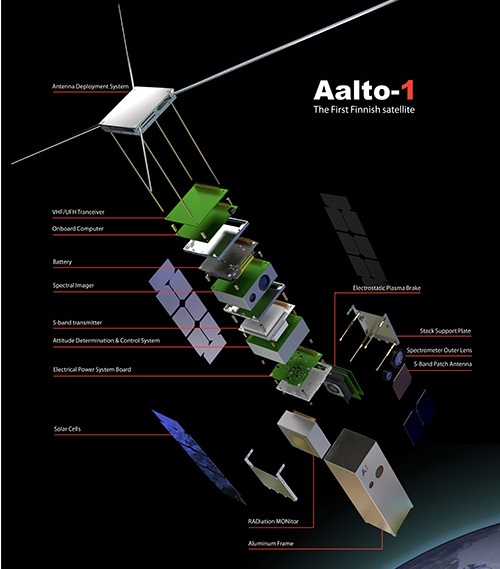
Aalto-1 is the first Finnish Satellite and the product of a student satellite project initiated in 2010 at Aalto University by a group of grad students enrolled in a Space Technology special assignment course. The satellite is a 3U CubeSat outfitted with an Imaging Fabry-Perot Spectrometer, a Compact Radiation Monitor and an Electrostatic Plasma Brake.
The project has been coordinated by the Department of Radio Science and Engineering with additional support by various departments of Aalto University as well as other institutions providing the payloads – VTT Technical Research Center of Finland for the spectrometer, the Universities of Helsinki and Turku for the radiation monitor, and the Finnish Meteorological Institute for the plasma brake.

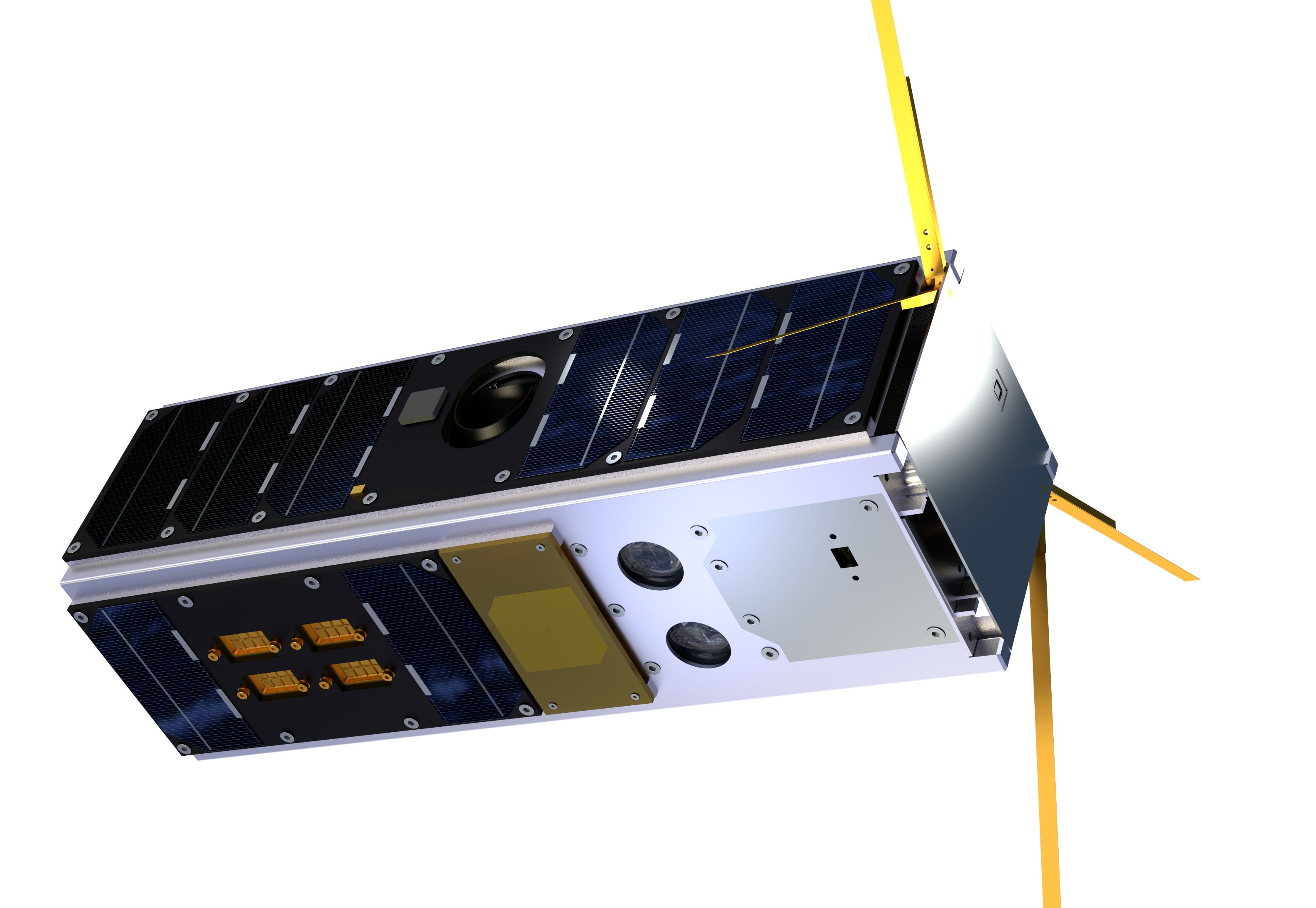
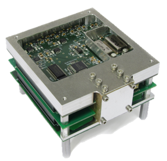
Aalto-1 is a 3U CubeSat 10 x 10 x 34 centimeters in size with a mass of four Kilograms, utilizing an active attitude control system and body-mounted solar cells for power production. The mechanical subsystem of the spacecraft comprises two PCB fastener stacks joined by stack plates and the outer frame which itself consists of two aluminum parts 1.5mm in thickness that form the 3U satellite structure.
The satellite is covered with solar cells on all available surfaces not used by the payload and communications antennas, creating three long side solar panels and one small nadir panel on the instrument side. Azur Space triple-junction solar cells with high efficiency are used to allow the two large solar panels to deliver a maximum power of 10 W, the medium-size panel delivers up to 7.5W and the small panel 2.5 Watts. The orbital average power, per the mission’s requirements, will be 4.8W, delivered to a stack of three batteries for power supply during peak demands.

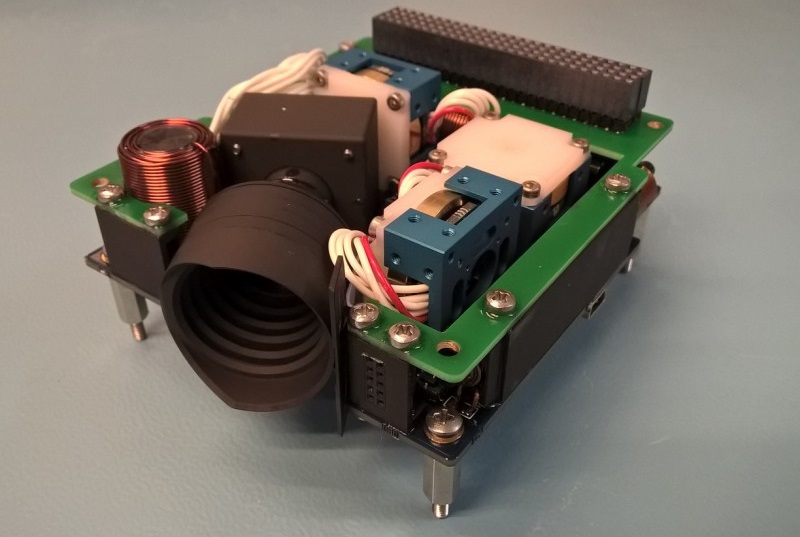
Aalto-1 uses the iDACS-100 Integrated Attitude Determination and Control System provided by Berlin Space Technologies and Hyperion Technologies, Delft as an integrated unit consolidating all attitude determination and control functions. iDACS-100 is a self-contained attitude control solution, consisting of a star tracker, MEMS sensors, three reaction wheels and magnetic torquers and a star tracker unit plus a computing unit capable of attitude determination and actuation of the wheels and torquers for three-axis control as commanded by the main flight computer. iDACS-100 is 95 by 90 by 32 millimeters in size and weighs 350 grams, making it one of the smallest full-functional ADCS packages currently in operation.
For iDACS-100, Berlin Space Technologies provides overall management and system design as well as the structure, assembly and testing of the unit while Hyperion is responsible for the electronics design and production of the wheels and torquers.
iDACS-100 requires 0.5 to 1.8 Watts of electrical power and communicates with the CubeSat platform via an RS485 serial link and I2C circuitry.
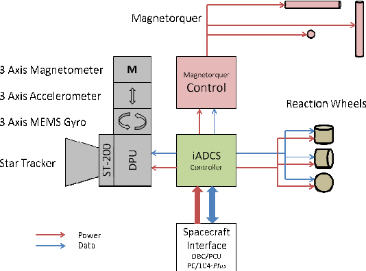
The primary sensors of iDACS are the Micro-Electro Mechanical System (MEMS) suite that measures body rates and acceleration and is employed during the initial de-tumble to enable the Star Tracker to acquire an attitude solution. A magnetometer within the MEMS suite provides information on the current magnetic environment for actuation of the magnetic torquers.
The ST-200 star tracker captures imagery of the star-filled sky that are processed by an onboard algorithm with a star catalog to calculate the precise three-axis orientation of the satellite with a typical attitude knowledge of 30 arcsec. Auxiliary sensors used by iDACS are a series of Fine Sun Sensors that provide knowledge on the solar vector for safe mode attitude control. A GPS receiver connected via I²C provides time references a precise position measurements.
The actuators of the iDACS system are three RW200 reaction wheels with a torque of 0.087mNm and a momentum capacity of 1.5 mNms, enabling attitude slew rates of over 1.5 degrees per second. The achieved pointing accuracy will be better than one degree, permitting iDACS to be used on Earth observation missions. Three magnetic torquers are available for use in attitude control during spacecraft safe mode and for regular momentum dumps from the reaction wheels
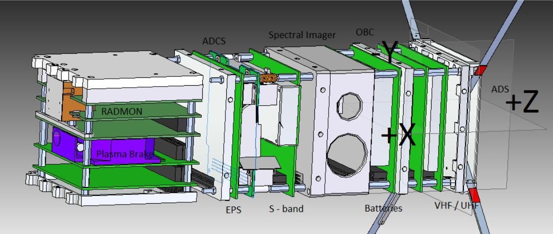
At the center of the satellite is an onboard computer in charge of actuation of all satellite systems and handling of systems telemetry data as well as science data from the payload. It uses an ARM 9 processor with external RAM, EEPROM, DataFlash, NANFlash and a Micro SD as primary data storage device for science data. The computer runs a customized GNU/Linux operating system with several built-in features to increase the system’s reliability. Auxiliary systems to the OBC are an I²c bus controller for intra-satellite communications and LVDS transceivers interfacing with data-intensive systems like the payloads.
Aalto-1 uses a conventional VHF/UHF transceiver for command reception in VHF and systems telemetry downlink in the UHF band. Antennas for the UHF/VHF comm system and the satellite’s radio beacon automatically deploy from the forward face of the satellite after separation from the launch vehicle.

Payload data is downlinked through an S-Band terminal at a frequency of 2.402 GHz using a Texas Instruments transceiver unit and an S-Band patch antenna to downlink data at 1 Mbit/s with a total downlink volume of 41.6MB for favorable ground station passes.
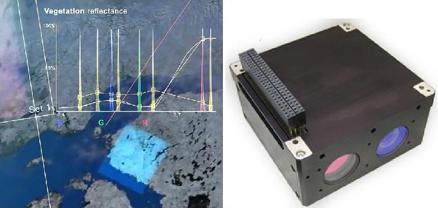
Aalto-1 carries three scientific instruments, the Aalto-1 Spectral Imager (AaSI) is considered the main payload and is primarily intended as a technology demonstration which, if operating successfully, can make a contribution to remote sensing science. The other two payloads are the Radiation Monitor (RadMon) and Electrostatic Plasma Brake (EPB).
The AaSI instrument was developed by VTT Technical Research Center based on a tunable Fabry-Perot Interferometer capable of capturing two-dimensional images at up to three selected wavelength bands simultaneously. The spectrometer consists of two highly reflective surfaces separated by a tunable air gap, allowing the sensitive wavelength of the instrument to be adjusted as needed. To measure more than one channel at the same time, multiple orders of the spectrometer’s transmission function can be matched to the sensitivities of the image sensor (e.g. the red, green and blue pixels of a Bayer filter).
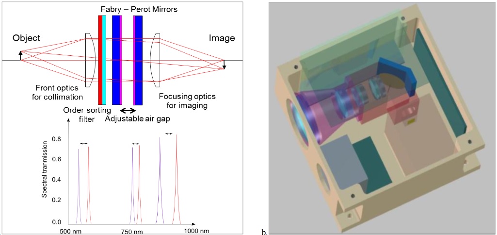
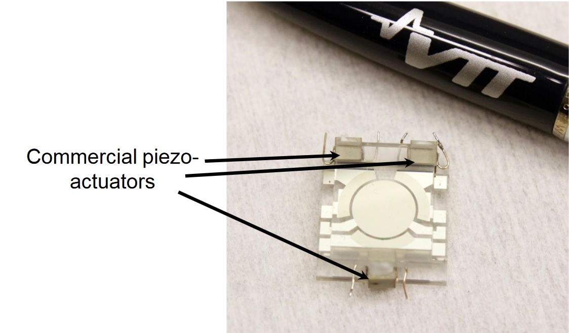
Three piezo actuators are responsible for the positioning of the reflective surfaces and can adjust the air gap from 0.5 to 3 micrometers, corresponding to a spectral range of 500 to 900 nm, covering the visible wavelengths. The instrument’s mirrors have a 50nm silver coating with a 50nm protective layer of silicon dioxide and a 4nm layer of titanium acting as adhesive to hold the layers together. The mirrors are fixed to the piezo actuators and a capacitive feedback loop is used to ensure proper positioning of the mirrors-
AaSI delivers a spectral resolution of 10 – 30 nm and a spatial resolution of 240 meters (from an altitude of 700 Kilometers) across a 10 x 10° field of view which creates a ground swath of 120 Kilometers from the 700-Kilometer reference orbit. The instrument employs a conventional 2048 x 2048-pixel CMOS detector, binned to 512 x 512 pixels for the spectral images.
In addition to the spectrometer instrument, AaSI hosts a visible camera to capture full-color images of the same location imaged by the spectrometer to provide visual validation of the imaged area and help in the selection of spectral frames to be downlinked, rejecting frames with excessive cloud cover. The VIS camera has a 30 x 19-degree Field of View and uses a 1910 by 1270-pixel detector assembly yielding a ground resolution of 100 meters. Both image sensors have a global shutter function to ensure each pixel is exposed simultaneously.
The source data rate from AaSI depends on the number of wavelength bands and image size chosen for data acquisition, varying from 2MB to 500MB per picture, the average will be 7.8 MB per picture with fifteen 512×512 pixel images with a 16bit depth.

Data is transmitted through a 3-wire Serial Peripheral Interface to the onboard computer for storage until a downlink is requested. The read-out chain of the AaSI instrument is largely based on Field Programmable Gate Array Technology, employing a 32MB SRAM buffer to hold 16 megapixels of image data. An SPI-over-LVDS link is used to transmit the AaSI science data to the satellite.
Calibration of AaSI will use bright spectral features of known properties like the Sahara Desert and the oxygen absorption band at 750-760nm as well as onboard calibration with 500 and 900 nm filter edges.
The primary aim of AaSI is demonstrating a miniaturized spectral imaging system that provides flexibility and reduced data rate for well defined applications by means of tuning the spectrometer’s spectral bands to the wavelengths required for a specific purpose. The small size of the instrument could enable large constellations of spectral imaging systems to deliver data on a global scale at rapid revisit intervals for various remote sensing applications.
The Radiation Monitor of the Aalto-1 satellite was developed by the Universities of Helsinki and Turku and is a small space-based particle telescope for the measurement of proton and electron influx in the Low Earth Orbit Regime. RadMon comprises two adjacent detector elements, a thin Silicon detector to measure particle energy loss and a thick Thallium-doped Caesium Iodide scintillator to measure the residual energy of the particles stopping within the telescope.
Scintillator crystals have the ability of absorbing energetic particles and re-emitting their energy in visible radiation which can be detected with a photomultiplier tube that converts the visible photons into electrons through the photoelectric effect and detects the current using detector electrodes. RadMon covers an energy range of 10 to 200 Mega-electronvolt for protons and 0.7 to 10 MeV for electrons and provides information on particle count rates for flux determination and energy information in several passbands in the available energy range.
RadMon uses a brass frame around all sides of the detector with the exception of the optical axis and particles pass through a 300µm Aluminum window before reaching the Si detector and CsI scintillator. Signals from both detector elements are needed for a particle to be registered. The total data volume for RadMon is no more than 1MB per 24 hours and the aim is to gather data for six to twelve months to generate a map of the flux of energetic particles in LEO and its temporal evolution.
The Electrostatic Plasma Brake (EPB) is a variation of the electric solar wind sail invented by the Finnish Meteorological Institute, intended to deorbit a satellite after its useful life for space debris mitigation. EPB consists of a multiline tether that is deployed into the ram flow of ionospheric plasma where an electrostatic force on the order of a few millinewtons can be created for propellant-less propulsion.

There are a number of advantages of electrodynamic tethers over other Active Debris Removal proposals, first and foremost the fact that they require no propellant and only very little electrical power because the electromagnetic force generating the thrust component is created by the tether current’s interaction with the geomagnetic field. Also, tether-based systems require no active guidance in the form of thrust vectoring and no attention has to be paid to the mass characteristics of the debris piece.
The EPB system consists of a 100-meter long and 25 to 50µm wide tether comprising redundant strands to avoid a total failure to due strand severing. In the stowed configuration, the tether is wound around a 53-millimeter reel which will unwind at a speed of 1 to 3mm/s by means of an electric motor and a one-gram mass at the end of the tether.
For the EPB test, the tether will be flown in positively and negatively charged modes to examine the Coulomb force delivered by the tether in both modes. A small cold cathode electron gun will be used to complete the circuit for the positive mode.
When the tether is deployed, the Coulomb force will be measured by switching the tether voltage on and off in a synchronous pattern with the satellite’s rotation, e.g. turning the tether voltage on when the tether moves downwind with respect to the plasma ram flow and switching off when it moves upwind. This will result in an increase in the tether’s and satellite’s spin rate accumulating over several periods which can be used to calculate the tether force. A second way of determining the effect of the tether will come through an increase in orbital decay.