
OSIRIS-REx Spacecraft
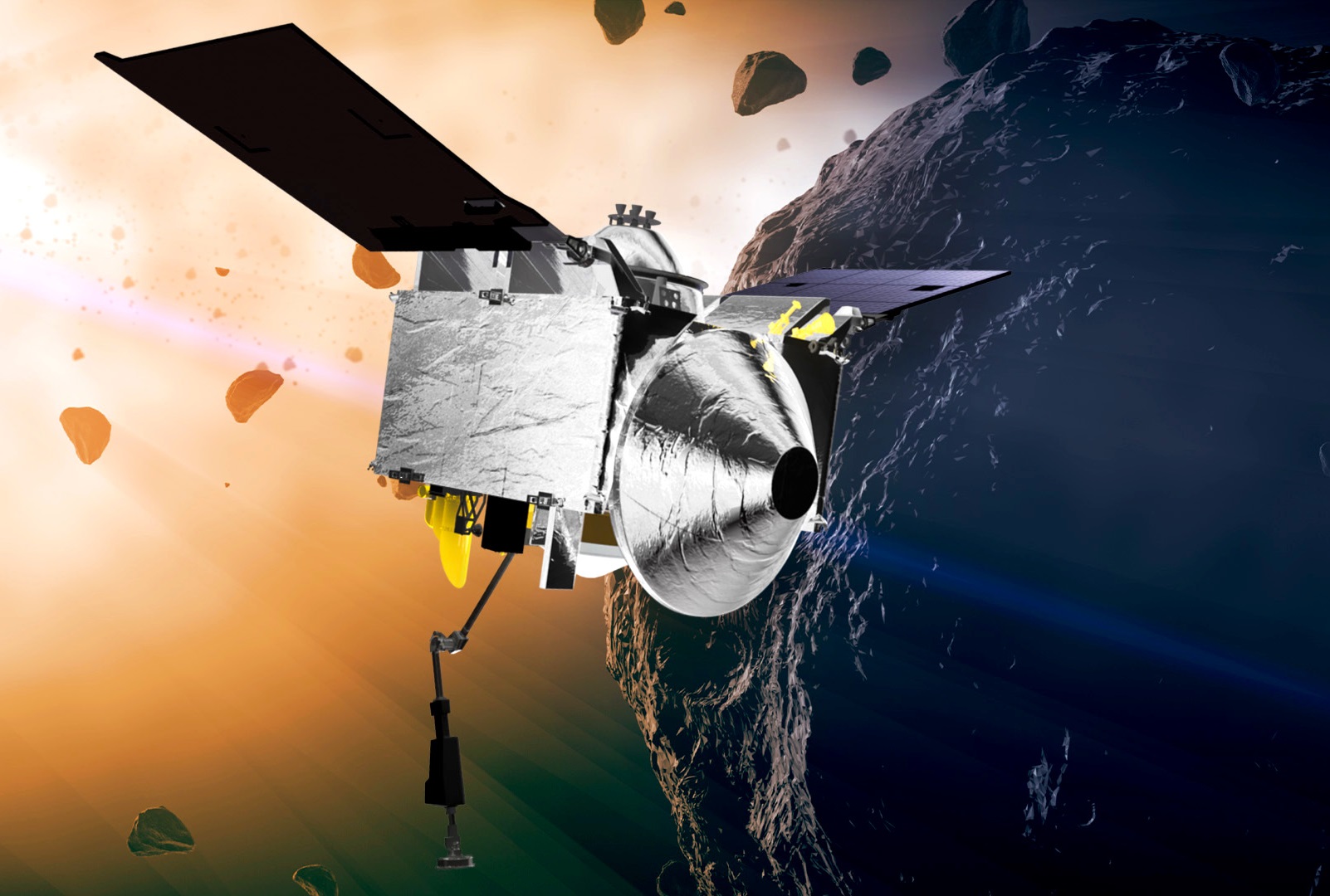
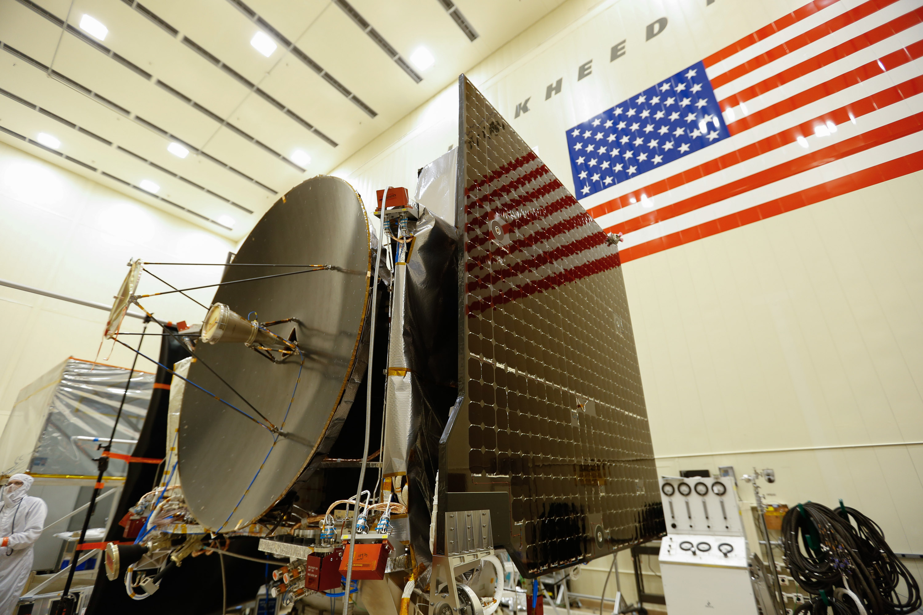
The OSIRIS-REx spacecraft, setting out on a complex asteroid sample return mission of seven years, was built by Lockheed Martin Space Systems based on the Mars Reconnaissance Orbiter and the MAVEN spacecraft also orbiting Mars.
Leveraging the key heritage design components of these two missions that have proven successful over long-duration flights reduces overall risk for the long OSIRIS-REx mission and lowers the overall development cost of the spacecraft.
Given the lengthy mission duration, the spacecraft has been built with healthy resource margins in mind as well as a fully redundant subsystem architecture with extensive cross-strapping between systems.
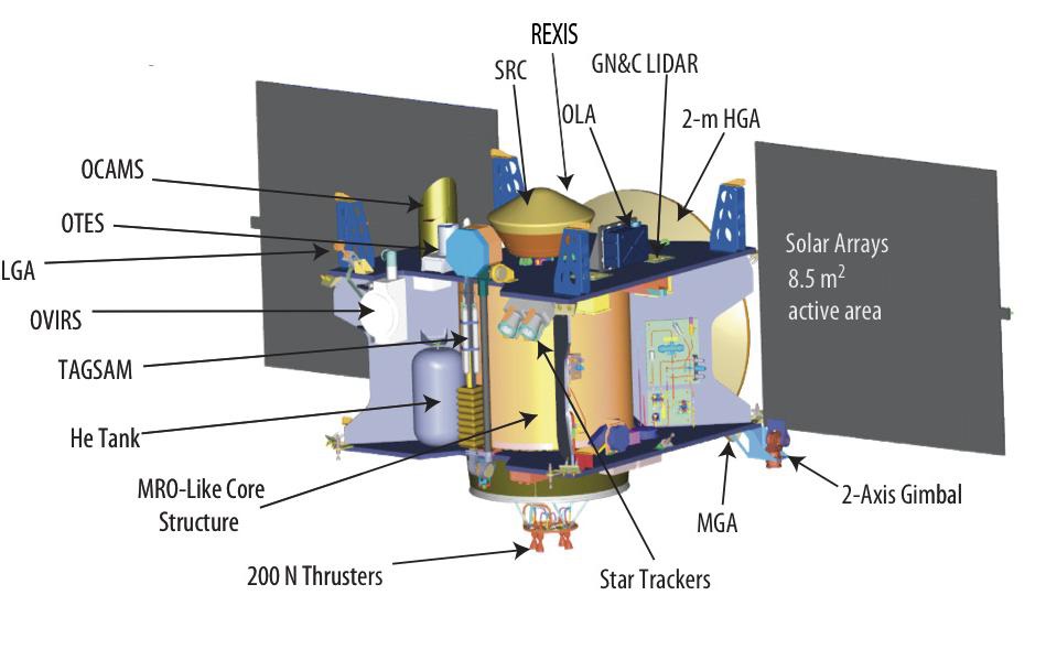
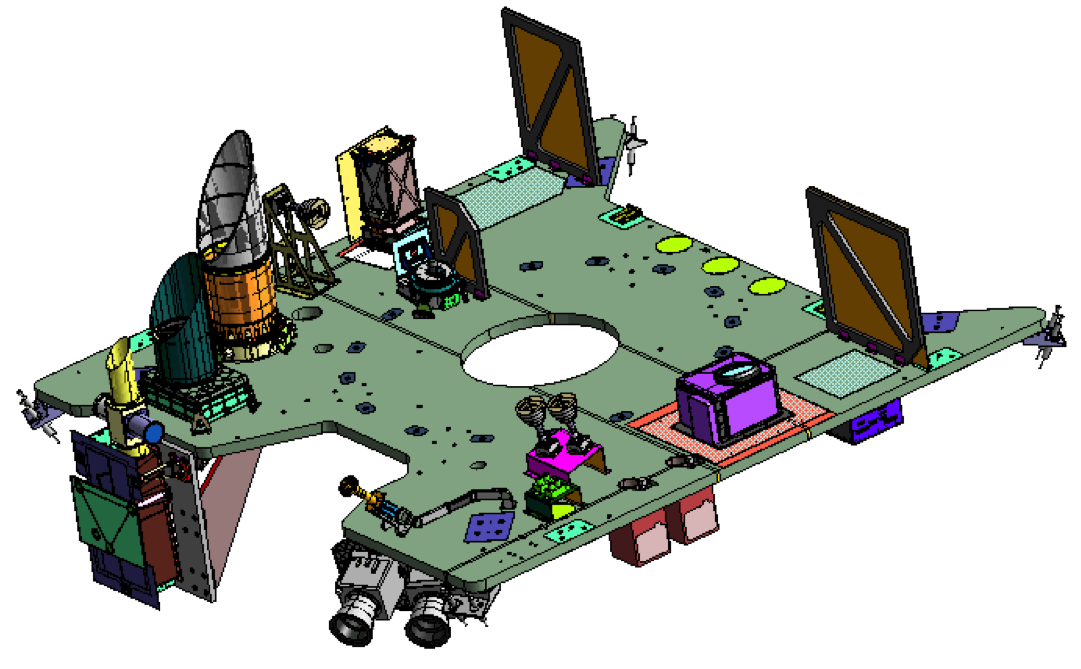
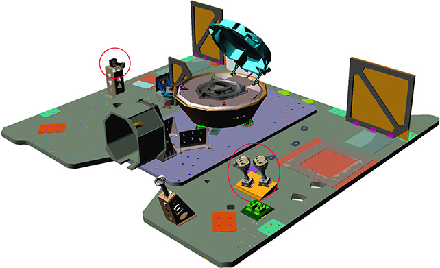
The OSIRIS-REx spacecraft is comprised of the following principal components: the spacecraft bus (containing the spacecraft structure and all supporting subsystems for the operation and control of the vehicle), the Touch And Go Sample Acquisition Mechanism TAGSAM, the Sample Return Capsule SRC (using heritage from the successful Stardust mission), and the five science instruments responsible for the remote-sensing campaign at Bennu.
Spacecraft Structure

The OSIRIS-REx spacecraft measures around 2.4 by 2.4 meters and stands 3.15 meters tall when in its stowed launch configuration. The spacecraft has a dry mass of 860 Kilograms and a baselined launch wet mass of 1,955 Kilograms with a 155-Kilogram addition possible when filling the propellant tank to the maximum.
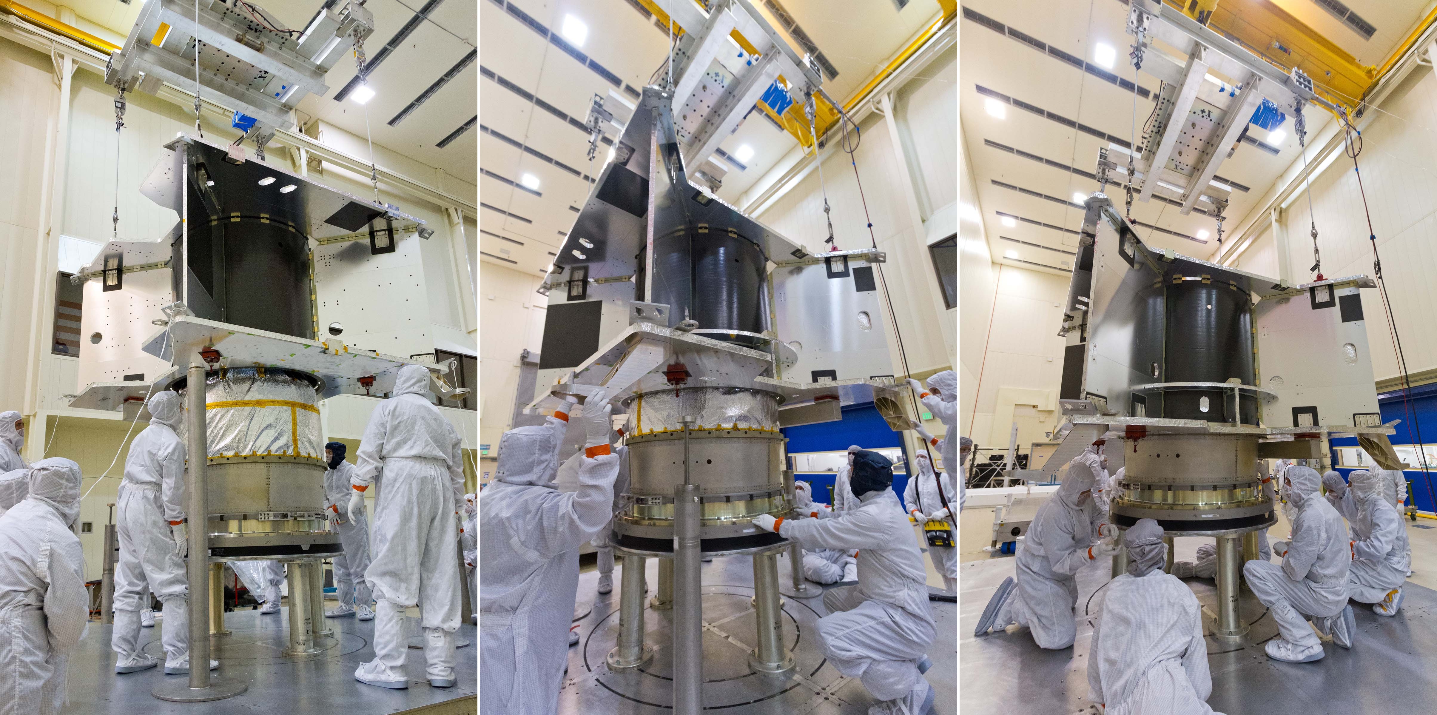
The cubical satellite platform is 2.3 by 2.3 by 2 meters in size, consisting of aluminum honeycomb sandwiched between graphite composite face sheets. The core of the structure is a 1.3-meter diameter cylinder that encloses the propellant tank of the spacecraft.
Mounted radially on the cylinder are composite sheets that are attached using metal fittings. The cylinder, the radial sheets and the exterior panels are used as mounting platforms for spacecraft equipment and serve as load-bearing structure. The primary structure has a mass of 160 Kilograms and is capable of supporting the entire mass of the spacecraft and loads experienced during launch.
Two decks, the forward and aft deck, are installed on the top and bottom of the Central Cylinder with the upper panel supporting the Sample Acquisition and Return Assembly (SARA), the science instruments, navigation equipment and antennas. The aft deck facilitates the batteries, medium gain antenna, reaction wheels and solar array gimbals.
Propulsion System
The propulsion system of the OSIRIS-REx mission is based on that developed for the Mars Reconnaissance Orbiter and later customized for the MAVEN mission and the Juno spacecraft exploring Jupiter.
OSIRIS-REx hosts a total of 28 engines divided into four groups: a bank of four high-thrust main engines, six medium-thrust engines, 16 attitude control thrusters and a pair of specialized low-thrust engines for the Touch-and-Go sample collection maneuver.
All thrusters installed on the OSIRIS-REx spacecraft are fed from a central propellant tank holding the Hydrazine supply needed for the mission. As monopropellant thrusters, the engines use the decomposition of the Hydrazine (N2H4) monopropellant when flowing over a heated, metallic catalyst bed – creating a high-pressure gas expanded through the engine throat and released through the nozzle.
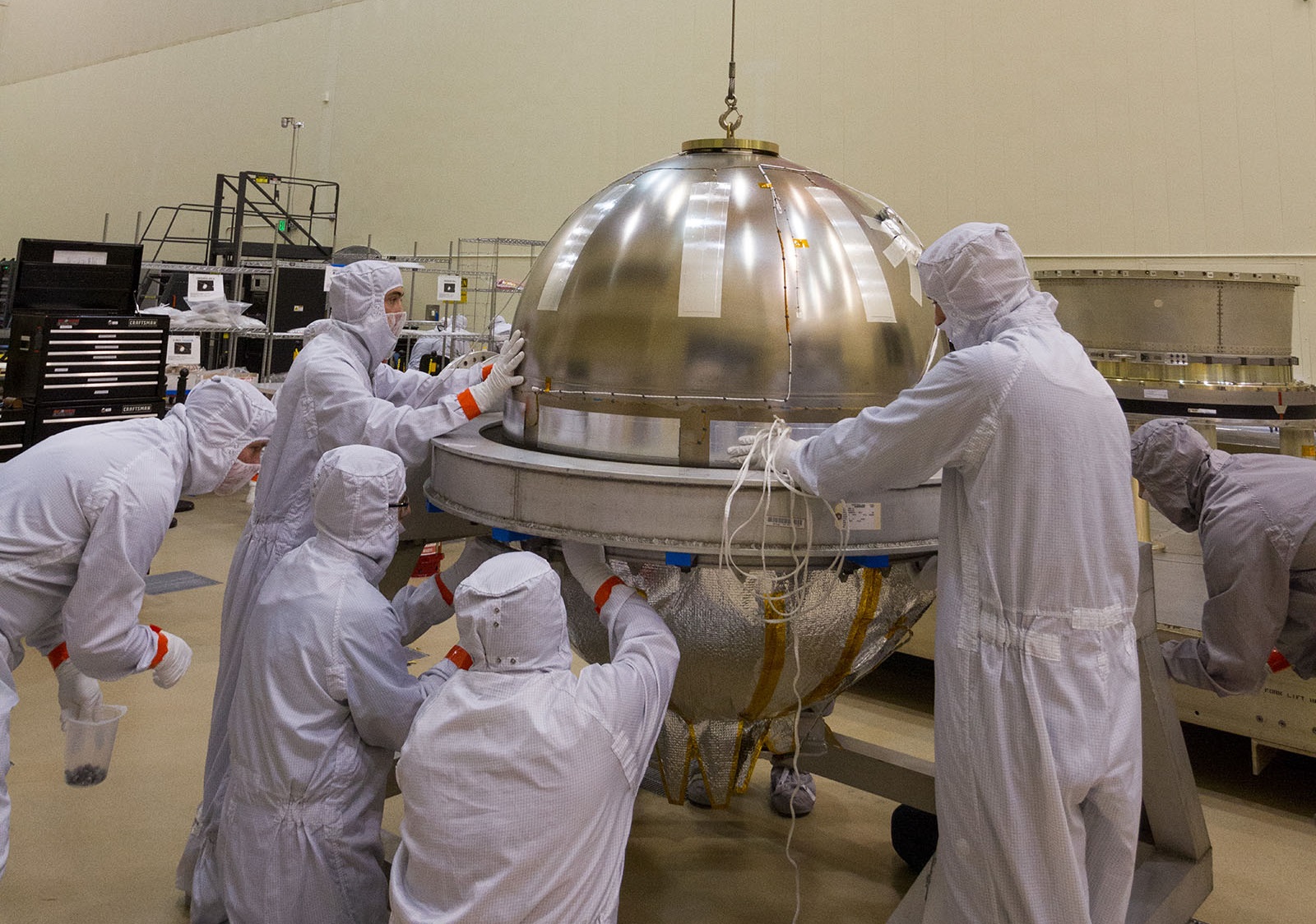
The central propellant tank resides within the structural cylinder of the spacecraft and stands 150 centimeters tall with a diameter of 124 centimeters, creating a volume of 1,300 liters. Built by ATK Aerospace, California, the tank consists of pure titanium to avoid corrosion by the Hydrazine and to provide stability within the backbone of the spacecraft structure. The tank can hold up to 1,245 Kilograms of propellant and is pressurized with Helium, stored in a high-pressure tank.
The pressurant tank consists of a composite overwrapped pressure vessel 42.4 centimeters wide and 75.2 centimeters tall with a volume of 80 liters. Kept at a pressure of 330 bar, the tank can hold 3.7 Kilograms of Helium fed to the propellant tank via a pyrovalve ladder and pressure regulators to keep the tank at a constant pressure during operation of the main engines. The tank is isolated after each main engine maneuver so that the propulsion system can be operated in blow-down mode when only the medium-thrust and attitude control engines are in use.
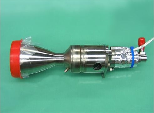
OSIRIS-REx is equipped with four Aerojet Rocketdyne MR-107S thrusters installed in a single bank on the base of the spacecraft to be able to deliver thrust for large delta-v maneuvers – the deep space maneuvers setting up for the Earth Flyby, the Asteroid Approach Braking Burn and the Asteroid Departure Burn.
Each of these engines provides a nominal thrust of 275 Newtons with a throttle capability of 85 to 360 Newtons. With the six engines at nominal throttle, OSIRIS-REx has a total thrust of 1,100 Newtons – 112 Kilogram-force.
MR-107S operates at a propellant feed pressure of 7 to 35 bar and a chamber pressure of 4 to 14 bar to create a specific impulse of 225 to 236 seconds. The engine ingests 36 to 155 grams of fuel per second depending on the thrust setting. It has an expansion ratio of 21.5.
MR-107S weighs 1,010 grams, measuring 22 centimeters in length and 6.5 centimeters in diameter, it uses a Moog Single Seat Valve. The engine is certified for nearly 30,300 duty cycles.

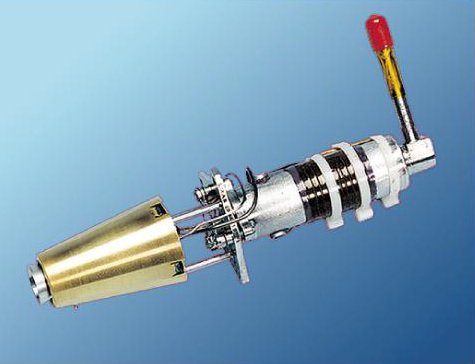
Six 22-Newton thrusters are used to deliver pitch and yaw control during main engine burns and they are available for smaller delta-v burns to clean up the spacecraft trajectory after the large main engine burns which are always associated with some inaccuracies. Two of the medium-thrust engines have the important task of accelerating OSIRIS-REx away from the asteroid after the Touch and Go sample collection.
MR-106L provides 22-Newtons of thrust with an operational range of 10 to 34 Newtons operating at a feed pressure of 5.9 to 27.6 bar and chamber pressure of 4.1 to 13.4 bar.
The thruster provides a specific impulse of 229 to 235 seconds. It has an expansion ratio of 60 and consumes 4.5 to 14.7 grams of propellant per second. MR-106L weighs 590 grams with a length of 18.2 centimeters and a nozzle diameter of 3.4 centimeters. The 22N thruster uses a Dual Seat prop valve and is certified for more than 120,000 duty cycles and long firings of up to 4,000 seconds.
For Attitude Control and unloading of the spacecraft’s reaction wheels, OSIRIS-REx hosts 16 low-thrust MR-111G engines operated at a nominal thrust of 4.5 Newtons.
The low-thrust engines accept a feed pressure of 5.5 to 27.6 bar and operate at a chamber pressure of 3.4 to 12.1 bar creating a specific impulse of 215 to 229 seconds. The engines have an expansion ratio of 74:1 and consume up to 2.4 grams of propellant per second at the highest inlet pressure. MR-111C can be operated in steady state mode and pulse mode with a minimum firing time of 15 milliseconds. They are certified for 420,000 total pulses and a firing time of 5,000 seconds.
The small thruster assemblies weigh 330 grams and are 17 centimeters long with a 3.8-centimeter nozzle.
All Aerojet Rocketdyne engines installed on OSIRIS-REx either use a catalyst comprised of granular alumina coated with Iridium (S405) or LCH-202, a proprietary catalyst material.
The two MR-401 ultra-low thrust engines installed on the OSIRIS-REx spacecraft are used during the Phasing Burn and Orbit Departure Burn at Bennu that has to line the spacecraft up for its sample collection with very high precision, factoring in the rotation of the asteroid to touch down at the desired landing site at the correct time.
These two engines have been adopted from Aerojet Rocketdyne’s Low Thrust Reaction Engine Assembly (LTR) originally developed for the GOES-R weather satellite and its “operate through” requirements. The engines can deliver a constant and predictable, low thrust making them ideally suited for their application on OSIRIS-REx. Each of the engines generates a thrust of 0.08 Newtons and a low specific impulse around 170 seconds.
Electrical Power System
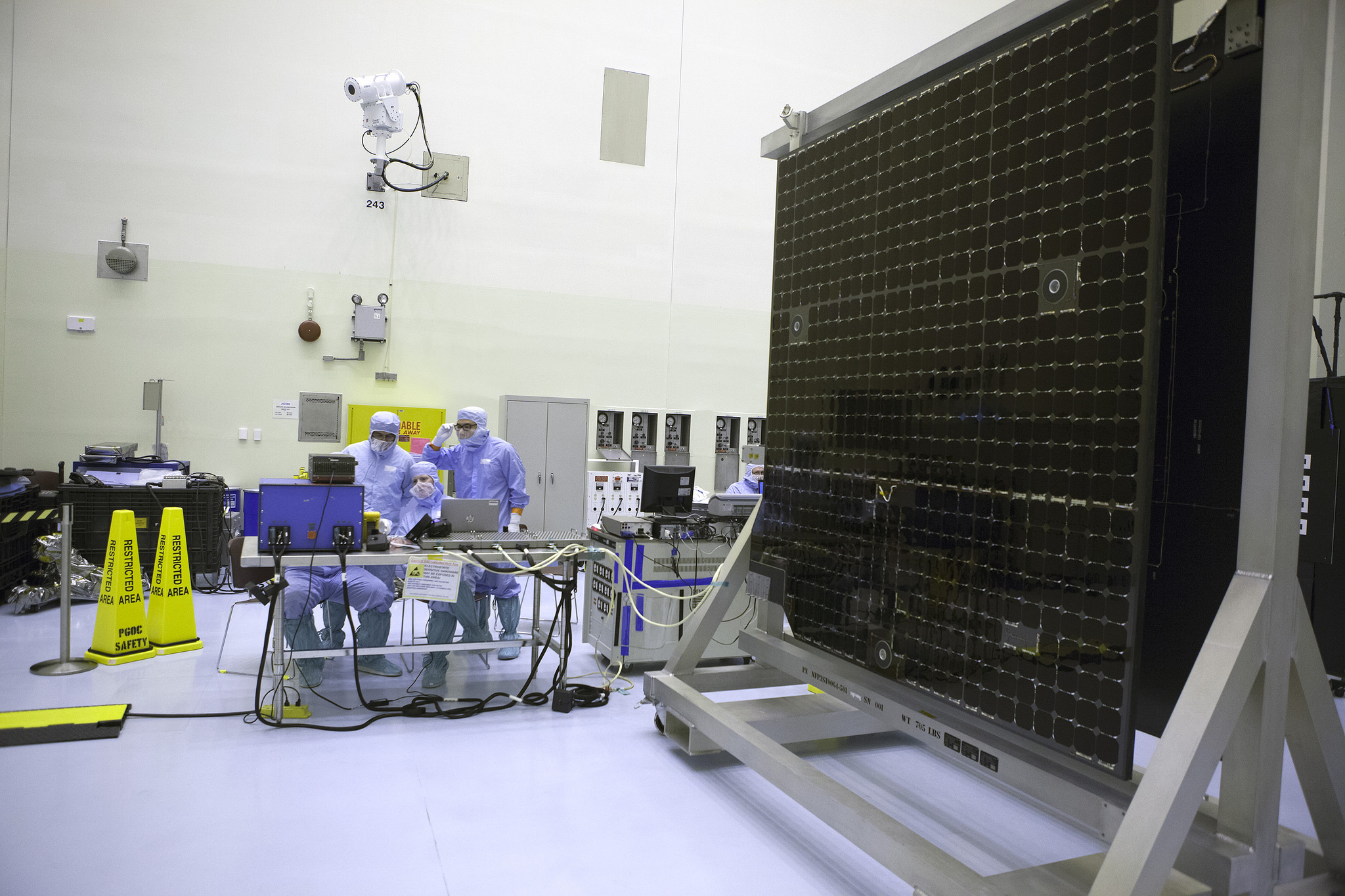

OSIRIS-REx has two power-generating solar panels affixed to the zenith-panel of the spacecraft. When deployed, the arrays give the spacecraft a span of 6.2 meters; their active area amounts to 8.5 square meters.
Covered with Gallium-Arsenide Solar Cells, the arrays deliver between 1,226 and 3,000 Watts of electrical power depending on the vehicle’s distance from the sun which will vary greatly over the course of the seven-year mission.
The two solar arrays are fixed and do not track the sun, requiring the spacecraft to face toward the sun for proper power generation. A gimbaling function of the arrays can cant them to the zenith direction to create a Y-wing configuration. The arrays will be moved for the Touch and Go sampling maneuver to avoid dust accumulating on the solar cells and increase the ground clearance in case the spacecraft tips over during the five-second contact.
Electrical power is stored in a pair of 30 Amp-hour Li-Ion batteries that come into play when the spacecraft is not in a sun-pointed attitude, for instance during the sample collection operation and propulsive maneuvers. Power from the arrays is delivered to a Power Distribution and Drive Unit which is comprised of a backplane and six different modules. It is responsible for delivering the Housekeeping Power supply, generating a regulated 28-Volt bus and a 28V pulsed power supply.
Also part of the EPS is the Pyro and Propulsion Unit which is in charge of providing activation of the various pyros installed on the spacecraft including the TAGSAM launch locks, Sample Return Capsule separation system, solar array locks, and propulsion valves.
Attitude Determination & Control

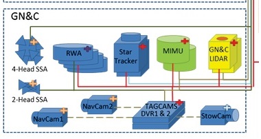
The OSIRIS-REx mission requires a specialized attitude determination, control and navigation system combining traditionally used components with customized equipment needed for the proximity phase of the mission when the vehicle will be close to asteroid Bennu.
The primary sensors for attitude determination are two flight-proven Star Trackers which collect multiple optical images of the star-filled sky each second which are then analyzed by an onboard algorithm comparing them to a catalog of bright stars to precisely calculate the three-axis orientation of the spacecraft.
A redundant system of two Inertial Measurement Units is also installed on the spacecraft. The Miniature Inertial Measurement Unit has extensive flight heritage and features a robust design using the GG1320 Ring Laser Gyro that provides precise rotation measurements. The system uses the basic principle that counter-propagating laser beams have different frequencies with the difference dependent on rotation rate which can be measured to calculate the rotation rate about the RLG’s sensitive axis. The MIMU weighs 4.5 Kilograms, being 23 by 17 centimeters in size.
It has an operational measurement range of +/-375°/sec at a low bias of under 0.005°/hour. The system can tolerate the radiation conditions in Low Earth Orbit and handles accelerations of up to 25G.
Sun sensors installed on OSIRIS-REx are an important part of the vehicle’s safety system. They take over attitude determination in the event of a spacecraft safe mode to ensure the solar arrays face the sun to guarantee sufficient power is available until the spacecraft can be transitioned back into normal operations.
Navigation data provided by the sensor complement is used by the vehicle’s flight computer to actuate the vehicle’s attitude control system. For larger attitude maneuver, OSIRIS-REx uses its small 4.5-Newton thrusters while standard vehicle pointing and attitude control is accomplished by four Reaction Wheels – three for each rotational axis plus one spare.
During main engine burns, attitude control for pitch and yaw is provided by the six 22-Newton thrusters while the low-thrust 4.5N engines keep roll rates stable. Attitude control during small dV maneuvers of the 22N thrusters uses the 4.5N thrusters as well.
The reaction wheels are spun by electric motors at variable speed that is changed when making attitude maneuvers. The thrusters are used for periodic angular momentum desaturation – slowing down the reaction wheels and countering the resulting force with the thrusters so that the wheels can then be accelerated during standard attitude operations.
Proximity Navigation
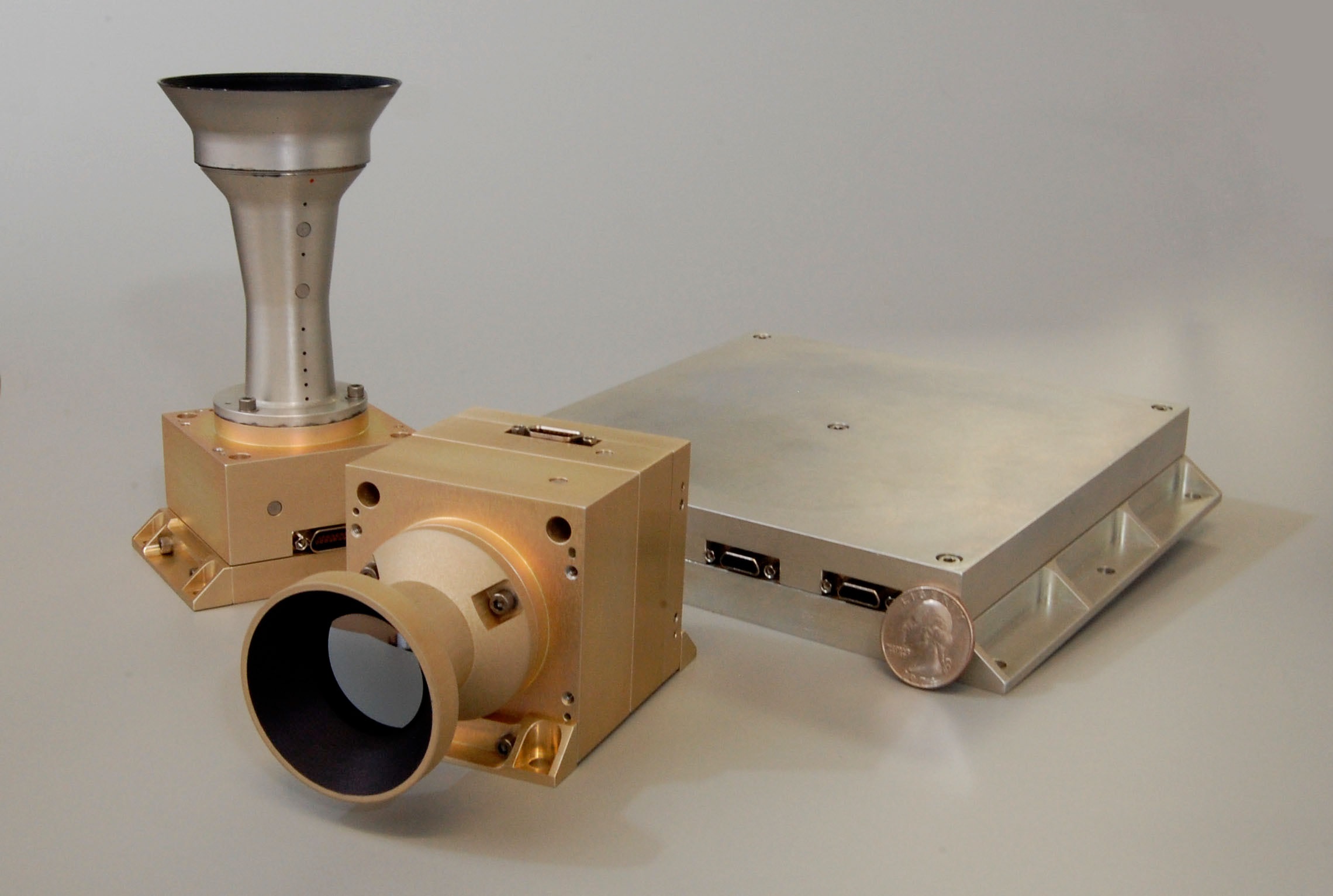
Two specialized sensors are onboard the OSIRIS-REx spacecraft to deliver assistance when navigating in close proximity to the asteroid – a Navigation LIDAR and TAGCAMS, a camera system.
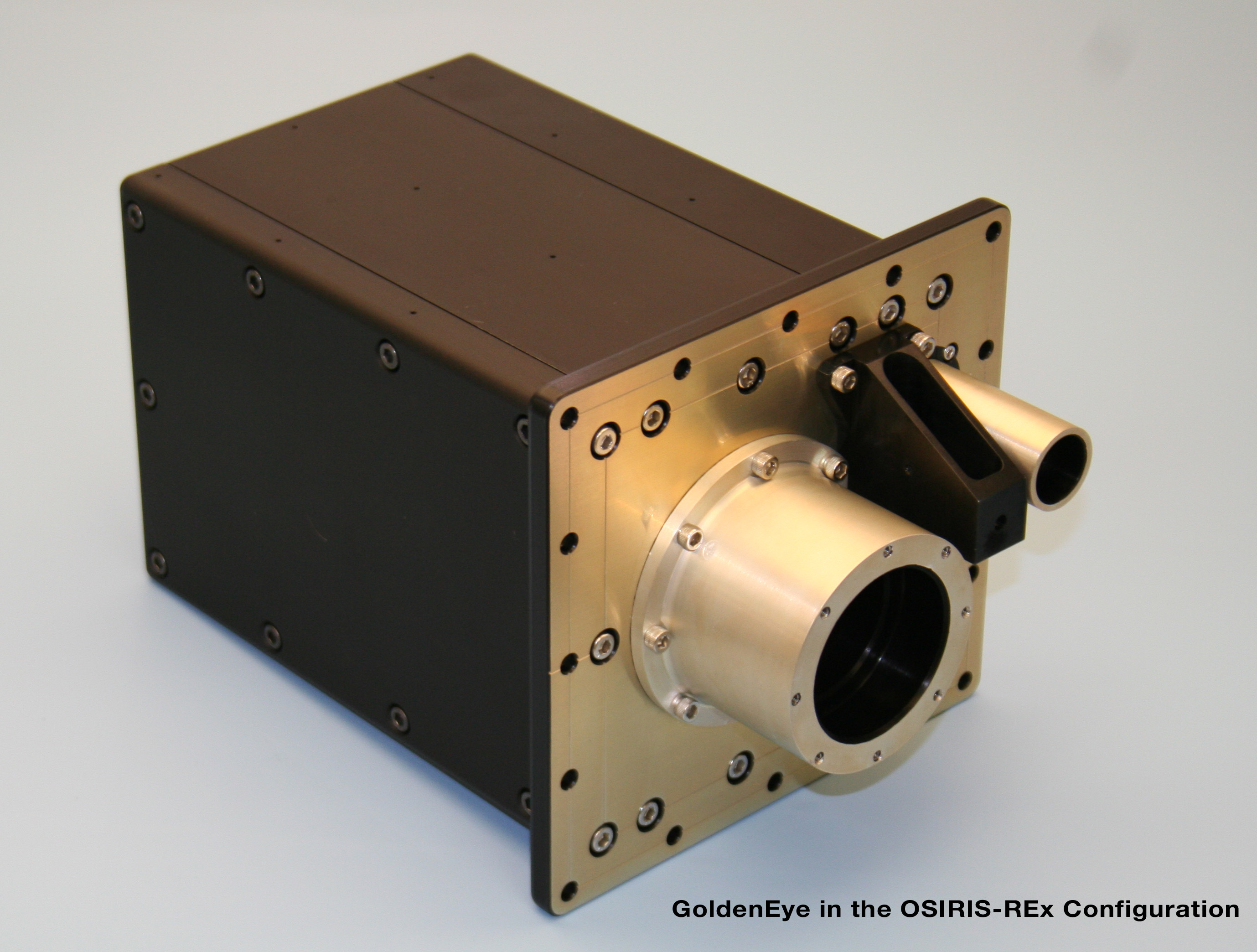
LIDAR – Light Detection And Ranging – bounces laser pulses off a target and hosts a pixel-sensor to detect the time it takes for the light to return to calculate the distance to the target as well as the target’s shape. The Navigation LIDAR on OSIRIS-REx is a 3D Flash LIDAR Space Camera manufactured by ASC, Advanced Scientific Concepts Inc.
The compact LIDAR system, just 14 by 20.6 by 16.5 cm in size, captures 128 x 128 independently triggered pixels at a read-out of up to 30 frames per second to deliver real time three-dimensional navigation data to the spacecraft computer.
The 6.5-Kilogram camera system can acquire targets from as far as three Kilometers. It operates at infrared wavelengths, emitting laser pulses at 1064 or 1570 nanometers and records the reflection through an Indium-Gallium-Arsenide detector array.
For OSIRIS-REx, ASC’s camera employs additional radiation shielding to tolerate a dose of 100 kRad and ensure the system will be operational after an extended cruise through the challenging radiation environment in deep space. The additional shielding accounts for 2.5 Kilograms of the sensor’s total mass.
The LIDAR delivers data with a range bias better than 20 centimeters and range noise under 30 centimeters.
The Touch And Go Camera System – TAGCAMS is comprised of three wide-field cameras and a digital video recorder. Two of the cameras are tasked with imaging asteroid Bennu and background stars during the approach phase of the mission to support optical navigation for trajectory fine-tuning while the third camera is installed to observe the transfer of the sample collected from the asteroid to the Sample Return Capsule.
TAGCAMS was developed by Malin Space Science Systems based on the company’s ECAM Modular Spaceflight Imaging System using three C50 camera heads with medium field-of-view lenses and a DVR8 digital video recorder. Each C50 camera head weighs less than 250 grams and acquires 2592 by 1944-pixel imagery employing 2.2-micrometer pixels, arranged either in a Bayer pattern for color imaging or with no filters for panchromatic imaging.
The DVR has a 128MB volatile buffer and non-volatile memory up to 32GB. Image processing is completed on the DVR board, supporting lossy JPEG and Huffman lossless compression as well as video compression standards such as h264.
The navigation cameras are capable of capturing 4th magnitude stars even when the bright asteroid takes up half the camera’s field of view.
Command & Data System
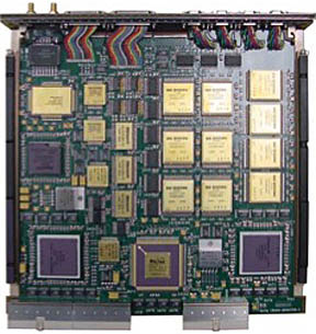
As a spacecraft based on MRO & MAVEN, OSIRIS-REx likely uses the trusted RAD750 as flight compute, though no documentation confirming the flight computer choice was available for this specific mission. Below are the specifications for RAD750:
RAD750 is a single-card computer manufactured by BAE Systems in Manassas, Va. The processor can endure radiation doses that are a million times more extreme than what is considered fatal to humans. The RAD750 CPU itself can tolerate 200,000 to 1,000,000 rads. Also, RAD750 will not suffer more than one event requiring interventions from Earth over a 15-year period.
“The RAD750 card is designed to accommodate all those single event effects and survive them. The ultimate goal is one upset is allowed in 15 years. An upset means an intervention from Earth — one ‘blue screen of death’ in 15 years. We typically have contracts that (specify) that,” said Vic Scuderi BAE Business Manager.
RAD-750 was released in 2001 and made its first launch in 2005 aboard the Deep Impact Spacecraft. The CPU has 10.4 million transistors. The RAD750 processors operate at up to 200 megahertz, processing at 400 MIPS. The CPU has an L1 cache memory of 2 x 32KB (instruction + data) – to improve performance, multiple 1MB L2 cache modules can be implemented depending on mission requirements.
RAD750 operates at temperatures of -55°C to 125°C with a power consumption of 10 Watts. The standard RAD750 system can tolerate 100,000rads.
The Data Handling System receives data from the payload and can send commands to the payloads as part of stored operational sequences. Data from the navigation sensors are also processed by the Data Handling Systems that in turn command the attitude control system and propulsion systems of the vehicle. Housekeeping operations such as the commanding of heaters based on temp sensor data and power management is also accomplished by the computer system.
The Mass Memory Board directly interfaces with the Telecom system of the spacecraft for data downlink and command uplink.
Telecommunications
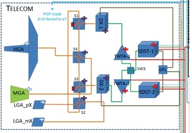
The telecommunications system employed by OSIRIS-REx is essentially an exact copy of the MAVEN system featuring a large directional high-gain antenna, a single medium gain antenna and a pair of omni-directional low-gain antennas.
The heart of the communications system are the Small Deep Space Transponder (SDST) and the Traveling Wave Tube Amplifier – two of each unit are installed on the spacecraft with cross strapping possible between all units as part of a redundant architecture. Power from the SDST output is split to both TWTAs and RF switches connect the receive antenna paths to either SDST receive port.
The SDST is a NASA/JPL design for deep space missions to unify a number of communications functions in a single unit – receiver, command detection, telemetry modulation, exciters, tone generator and control. Each unit has a mass of 3 Kilograms and supports command reception in X-Band and data transmission in both X- and Ka-Band (two bands being of importance for gravity science applications needed by many space probes).

Data for downlink is first sent through the SDST to generate the radio signals that are then amplified by a 100-Watt Traveling Wave Tube Amplifier from where the signals are then boosted into one of the three antenna types.
The High-Gain Antenna offers the highest data rate but only has a narrow field of view, requiring the spacecraft to be precisely pointed to Earth. The antenna is a 2.1-meter diameter dish with a dual-reflector X-Band system to achieve downlink data rates of up to 914kbit/s. It is made of a Kevlar honeycomb core between two composite face sheets.
Because the high-gain antenna is fixed on the spacecraft, the whole OSIRIS-REx probe has to be moved to point the antenna at Earth for its regular communications sessions.
The circular horn Medium Gain Antenna offers a larger field of view than the HGA but only achieves a fraction of its data rate. It is selected whenever the HGA can not be pointed directly to Earth for downlink of status telemetry, allowing Mission Controllers sufficient insight into the state of the spacecraft and the status of ongoing operations. The MGA will be in use for the critical Touch-and-Go sampling operation.
A pair of choked horn Low Gain Antennas, each with omni-directional coverage, provide low data rate communications via MFSK tones and carrier signal when neither the HGA or MGA can be pointed to Earth – for example during propulsive maneuvers requiring a specific spacecraft attitude to set up the appropriate thrust vector. Doppler tracking of the carrier transmitted by the LGAs provides sufficient information on the progress of propulsive maneuvers.