
OSIRIS-REx Instruments
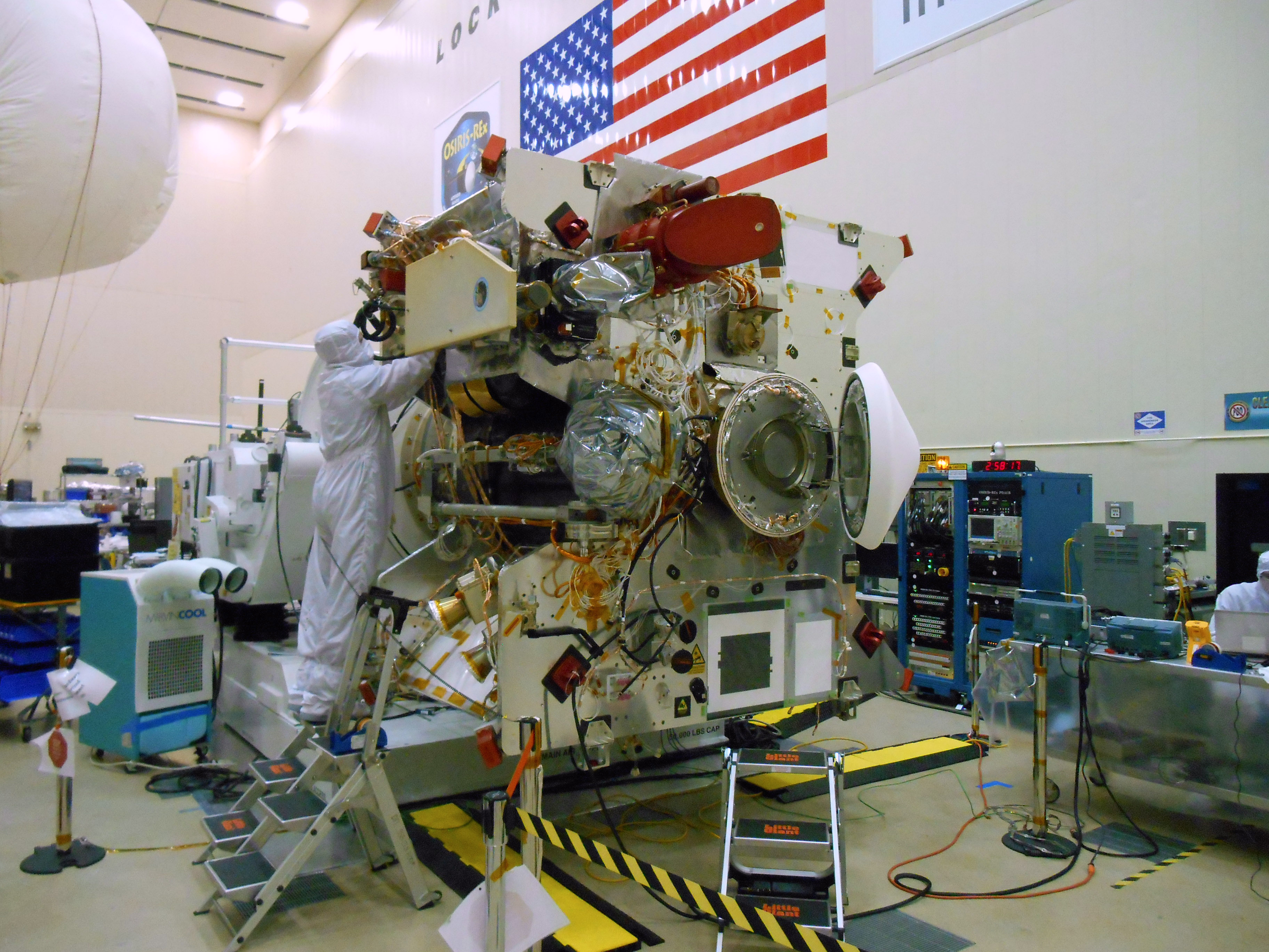
The primary objective of the OSIRIS-REx mission is to collect a sample from an asteroid and return it to Earth but the spacecraft will also carry out an extensive remote-sensing campaign at asteroid Bennu using a suite of scientific instruments. These include cameras and various spectrometers to learn about the composition and appearance of the asteroid’s surface while gravity science will reveal what lies beneath.
The OSIRIS-REx spacecraft is outfitted with six payloads – five remote-sensing instruments and the TAGSAM sample collection mechanism, plus the spacecraft’s communications equipment that doubles as a science payload when performing gravity science.
This page deals with the remote-sensing instruments and gravity science; for details TAGSAM, the Touch-And-Go Sample Acquisition Mechanism, refer to its dedicated page.
OCAMS – OSIRIS-REx Camera Suite
OCAMS – the OSIRIS-REx Camera Suite – is comprised of three separate cameras:
PolyCam collecting telescopic images during the approach to Bennu and high resolution once in formation,
MapCam tasked with collecting color imagery and the search for satellites around the asteroid, and
SamCam, a dedicated camera to deliver context imagery during the Touch-and-Go sample collection.
OCAMS was designed and built by the University of Arizona’s Lunar and Planetary Laboratory.
The first camera to pick up Bennu will be PolyCam that becomes active from a distance of around 2 Million Kilometers. It is a 20.3-centimeter telescope with a focal length of 63.5 centimeters and a narrow field of view of 0.8 degrees.
The telescope uses a Richey-Chretien arrangement which employs a hyperbolic primary mirror and a hyperbolic secondary mirror to eliminate off-axis optical errors compared to traditional reflecting telescopes which also have a smaller field of view.
PolyCam can detect stars down to the 12th magnitude, limited by spacecraft jitter. Its first task is to acquire the asteroid when OSIRIS-REx is still at great distance, providing assistance in optical navigation. Closer in, PolyCam can resolve surface features which helps in the exclusion of dangerous sites where sample collection will not be possible.
PolyCam’s name has been chosen because it can fulfill a pair of important tasks, collecting telescopic imagery from great distance and delivering high-resolution surface imagery during the close proximity phase of the mission – enabled by a refocusing mechanism.
PolyCam will deliver high-resolution imagery to characterize rock and pebble sizes on the surface for at least a dozen prospective sampling sites to help in the selection of the sampling location. The camera’s resolution will enable pebble sizes down to two centimeters to be identified.
MapCam is a medium-range camera tasked with the search for satellites and outgassing plumes on Bennu as well as mapping the asteroid in full color. It uses a five-lens optical design and a filter wheel between the optical elements and the focal plane to enable wide-band multispectral image acquisition.
The filter wheel has eight slots containing filters for full-color imaging (blue, green, red) and near-infrared, an empty slot for monochromatic imaging and a diopter lens to permit imaging at close range to the asteroid. MapCam has a field of view of 4 degrees.
MapCam’s primary task is the mapping of the entire asteroid surface in the various wavelength ranges enabled by the filter wheel. From a five-Kilometer distance, MapCam can see the asteroid make one full rotation every 4.3 hours and collect images at a resolution of 0.17 degrees. The refocusing lens allows MapCam to focus the surface from a distance of 30 meters for image collection of the sampling site.
SamCam is a close-range camera that serves a twofold task – collecting context imagery of the sampling site and verifying that the sampling process worked by imaging the sampling device.
It offers a wide field of view of 21 degrees and has a filter wheel with three identical filters plus an diopter filter. Three filters allow SamCam to restore its vision after a sample collection event in case the stream of nitrogen gas from the sampling device kicks dust into the camera assembly. This allows the camera to support at least three sampling attempts to make sure OSIRIS-REx fulfills its primary mission goal. The diopter is rotated into the optical path when focused images of the sample mechanism are needed (at very close range).
All three OCAMS cameras use identical focal plane assemblies with 1024 by 1024-pixel detectors manufactured by Teledyne Dalsa, Inc. Each has a mass of 0.6 Kilograms and draws 5.3 Watts of electrical power.
The detectors use an electronic frame-transfer shutter. All three cameras share a Camera Control Module installed underneath the payload deck and responsible for the analog to digital conversion, image compression and storage as well as commanding all camera sequences.
OCAMS completes extensive calibration after OSIRIS-REx arrives in space using multiple sources. Geometric calibration is accomplished by the collection of star cluster images to get a handle on the geometric distortion in the images, radiometric calibration is completed by star imaging, blocking filters are used for dark current monitoring, illumination lamps are available to assess pixel noise and imaging of the Earth-Moon system during flyby provides operational preparation for the mission at Bennu.
During approach to Bennu, PolyCam is the first to acquire the asteroid from a distance of 2 Million Kilometers as the asteroid begins to become visible against the star-filled sky. Imagery is used for optical navigation and the approach phase can be used for the measurement of the precise rotation rate, phase curve and other properties to verify data collected using ground-based sensors. Additionally, PolyCam will deliver initial data to develop a preliminary shape model of the asteroid.

Arriving at the asteroid, OSIRIS-REx enters a Survey Phase during which flybys of the polar regions are completed and images are collected from different positions with the asteroid at various phase angles. This phase will cover at least 80% of the asteroid’s surface generating high-resolution monochromatic images and full-color data. These initial maps will be used to construct a refined shape model, delineate craters, large boulders and identify surface features.
The Survey Phase will deliver 12 potential sampling locations.
After the Survey Phase, OSIRIS-REx is to enter a polar orbit around the terminator where the gravitational attraction and radiation pressure from the sun offset. Orbiting one Kilometer around the center of gravity of the asteroid places OSIRIS-REx several hundred meters above the surface from where imagery of 5-centimeter resolution can be collected by PolyCam. These images will narrow the search for a sample location from a dozen to only four sites.
The Reconnaissance Phase sets up flyovers of the four finalist sites and uses PolyCam with its refocusing mechanism, essentially converting the telescope into a microscope. Imagery captured by PolyCam during the flyovers provides information on the properties of the sample site candidates, resolving any dangers and confirming that the sites contain a sufficient amount of small regolith particles under two centimeters in diameter.
A final site is selected based on PolyCam imagery and will mark the start of a series of rehearsals of the sampling operation during which MapCam monitors the surface from a 30-meter distance using its refocusing capability. At this standoff distance, OSIRIS-REx matches the rotational period of the asteroid, providing an opportunity of extended monitoring of the sampling site.
During the actual Touch-and-Go Sample Collection, SamCam collects imagery at around one frame per second. The approach to sampling delivers context imagery of the undisturbed surface while imagery collected after the touch provides a look at the morphology of the site after contact with the probe. The final and possibly most critical task of SamCam is imaging the sample head to deliver a visual confirmation that material has entered the system.
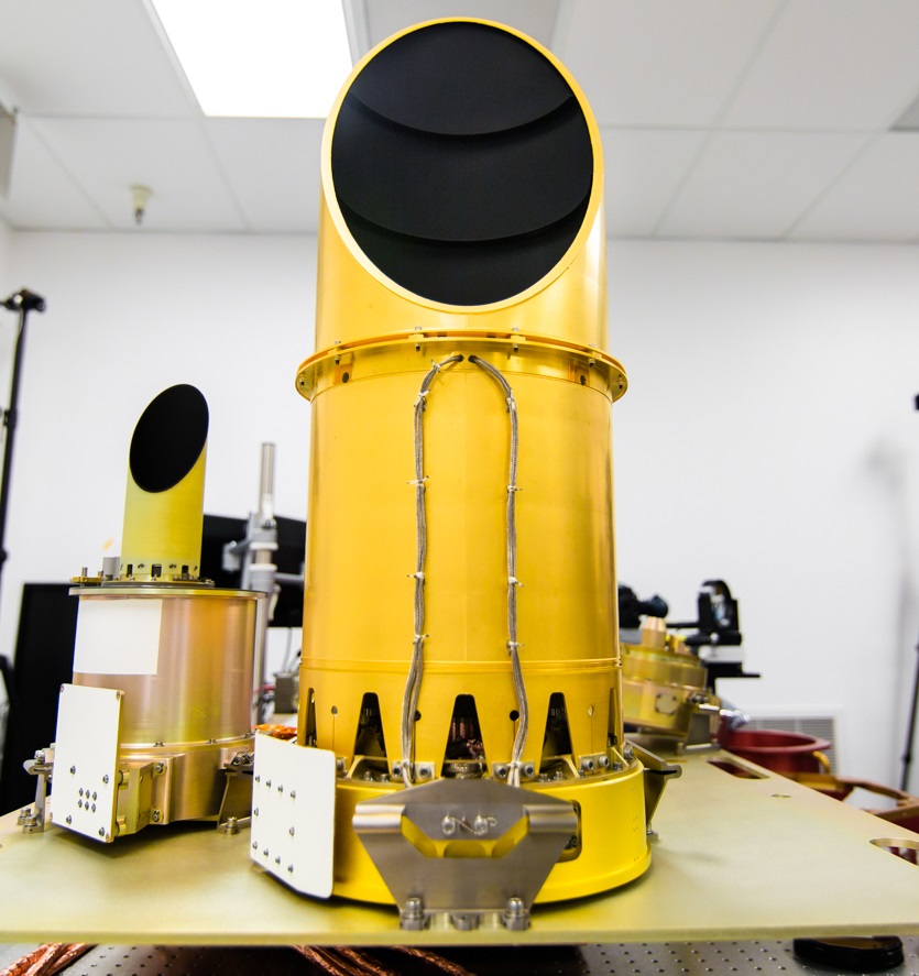
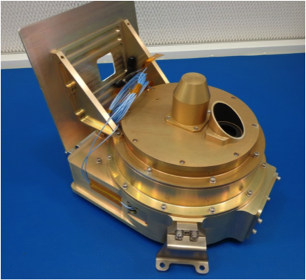
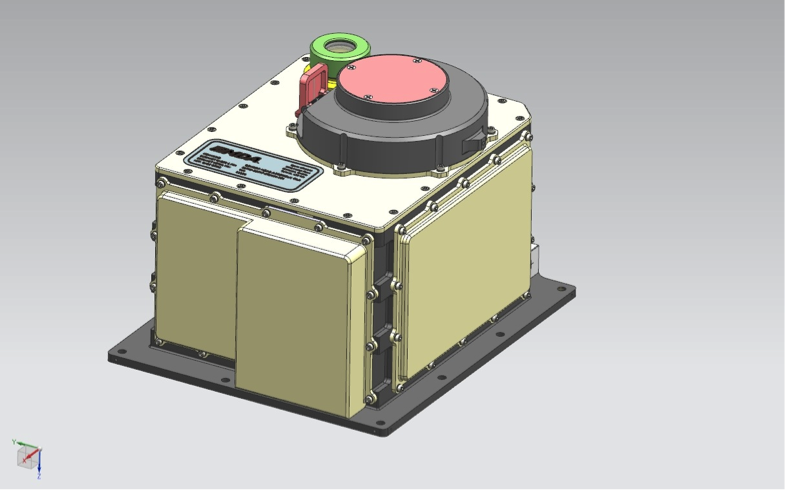
OLA – OSIRIS-REx Laser Altimeter
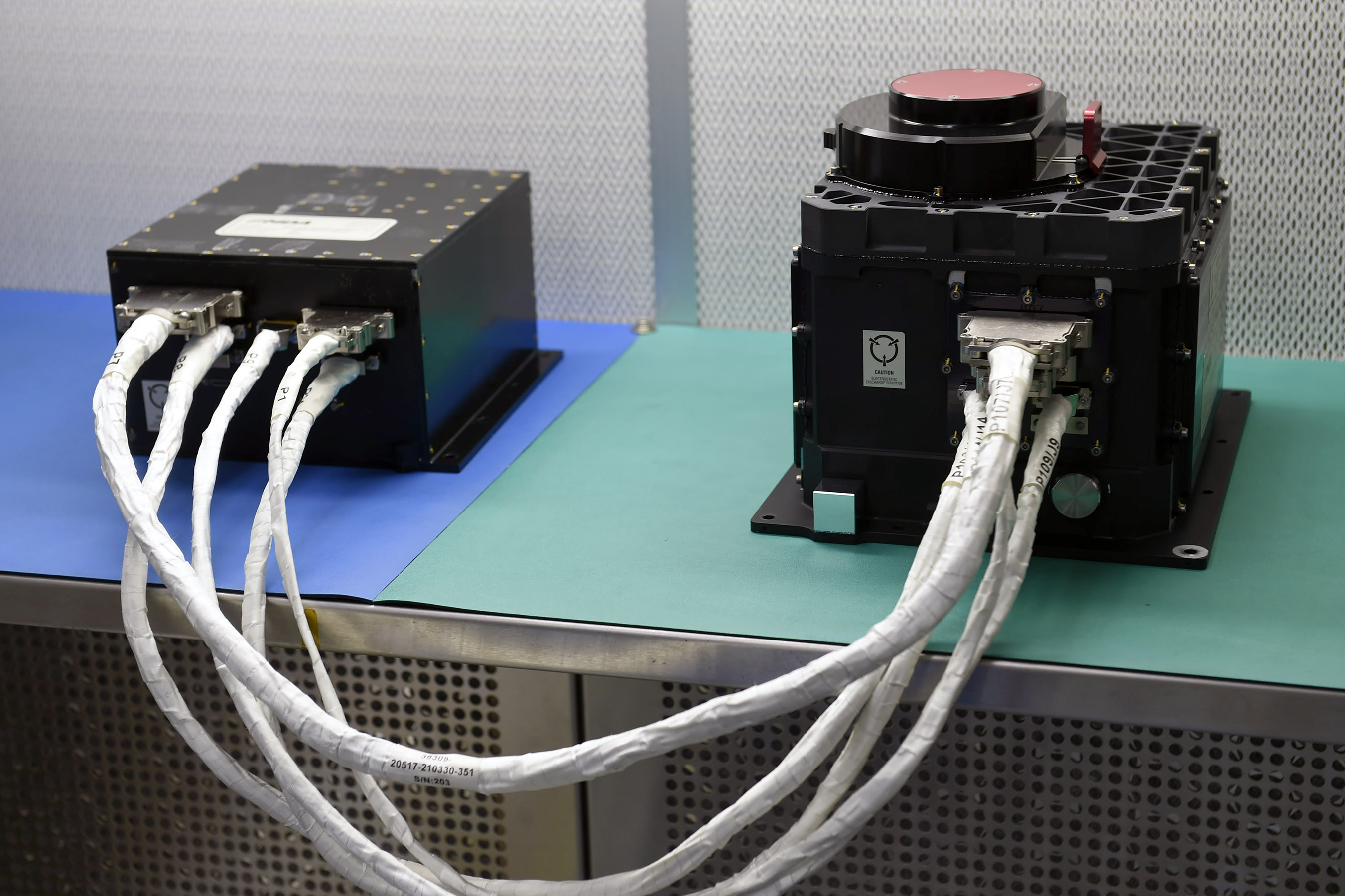
OLA, the OSIRIS-REx Laser Altimeter, is a scanning and LIDAR instrument to generate high-resolution topographical maps of the Bennu asteroid. The instrument will create a global topographic map of Bennu, local maps of candidate sampling sites, and support data collection from other instruments as well as proximity navigation around the asteroid.
OLA scans the surface of Bennu at specific intervals in the mission to rapidly map out the entire surface of the asteroid and support the calculation of the asteroid’s center of mass to refine gravitational studies conducted later in the mission.
The Laser Altimeter is funded by the Canadian Space Agency and was developed and built by MDA and Optec Inc. The instrument uses heritage from the XSS-11 satellite that practiced autonomous rendezvous operations in Earth orbit, and the landing radar of NASA’s Phoenix lander that touched down on Mars in 2008.
LIDARs and laser altimeters function by sending laser pulses toward a target and recording the reflected pulse in order to calculate the distance to the target or gain information on its shape.
OLA employs a pair of laser sources and a single receiver, expanding the previous LIDAR/Altimeter systems by adding a second laser source optimized for measurements at longer distances.
Both laser sources make use of 1064-nanometer Nd:YAG lasers (neodymium-doped yttrium aluminum garnet). The High-Energy Laser operates at a frequency of 100 Hz (sending 100 pulses per second) with a pulse energy of 1 milli-Joule while the Low-Energy laser operates at a frequency of 10 kHz (10,000 pulses per second) and a pulse energy of 10 micro-Joule.
The laser beams are directed onto a flexure mounted scanning mirror driven by Electro-Magnetic Actuators supporting a high-speed pointing capability. With this mechanism – and a high-accuracy read-out circuit, OLA can make 10,000 measurements per second, permitting range pictures to be taken by having the mirror sweep out a 2-dimensional path on the surface. The maximum beam deflection is 7° to either direction (X/Y).
OLA has a maximum operational range of 7.5 Kilometers and delivers accurate readings up to a distance of 200 meters. The accuracy of the measurement depends on the distance to the target and varies from 5 to 30 centimeters. This is also true for the size of the laser spot on the surface, varying from 1.5 centimeters to 2 meters.
Over the course of the OSIRIS-REx mission, OLA will map Bennu to a spatial resolution of 7 centimeters.
The High-Energy Laser source is in use at distances of 1 to 7.5 Kilometers while the Low-Energy laser operates for all distances inside 1 Kilometer.
OLA will generate a high-density 3D point cloud data to reconstruct the asteroid shape model at the highest density yet for a small body. It also delivers the slope information needed in the selection of potential sampling sites. Another important task of OLA is keeping track of the distance of OSIRIS-REx to the asteroid for processing of Gravity Science Data.
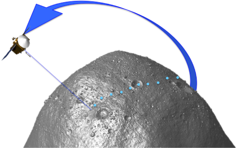
OLA will first acquire Bennu at a distance of 7 Kilometers and complete a detailed scanning campaign at the mission’s 5-Kilometer survey position. When OSIRIS-REx is in its 1km orbit, OLA will be operating continuously to support gravity science and complete a high-resolution mapping campaign to yield a global map at the best possible resolution. During reconnaissance passes a few hundred meters from the surface, OLA will yield very high-resolution maps of targets of interest.
OLA data will contribute to the study of Bennu’s interior, including its density and heterogeneity, revealing clues on its formation and evolution. Vertical roughness measurements will be used in an assessment of the evolution of local and regional surfaces.
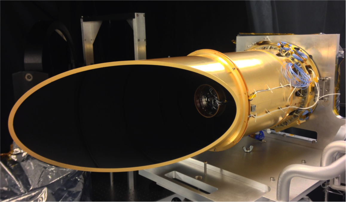
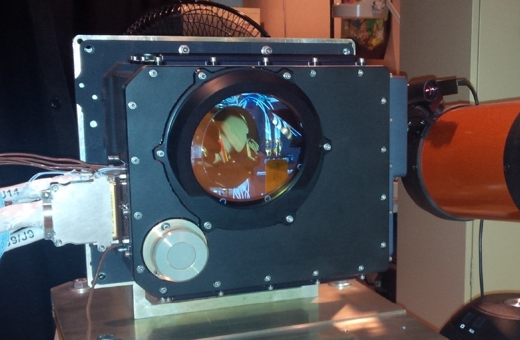
OVIRS – OSIRIS-REx Visible and Infrared Spectrometer

OVIRS is the OSIRIS-REx Visible and Infrared Spectrometer, one of three spectrometers that look at asteroid Bennu across the electromagnetic spectrum to reveal its surface composition, determining its mineralogy and supporting the search of organics.
The OVIRS instrument is a point spectrometer, is collects the VIS/IR wavelengths from a single spot on the surface, sweeping out image strips by combining the rotation of the asteroid and the rotation of the spacecraft around the optical axis of the spectrometer.
OVIRS covers a wavelength range of 0.4 to 4.3 micrometers and aims to generate a global spectral map of Bennu at a resolution of 20 meters with sufficient spectral accuracy to identify a variety of compounds including carbonates, silicates, sulfates, oxides, absorbed water and different organics.
Light entering the OVIRS instrument falls onto an off-axis parabolic mirror that images the surface of the asteroid onto a field stop which selects a 4-milliradian angular region of the image. The light from the 4-milliradian area is then re-collimated by a second off-axis parabolic mirror and sent to the Focal Plane.

OVIRS employs linear variable filters (wedge filters) placed in front of the detector to create the spectrum. The wavelength passing these two-dimensional filters varies with the position along one of the filter’s spatial dimensions, essentially assigning each detector region a specific wavelength.
This design was chosen for its flexibility and relative design simplicity compared to slit-type spectrometers that have complex optics and require dispersive elements, or Fourier-transform spectrometers with their elaborate scanning mechanisms.
The detector of the OVIRS instrument uses a 510 by 512-pixel region of a 1024 x 1024-pixel Mercury-Cadmium-Telluride H1RG array. This type of array is constructed by hybridizing the photosensitive pixel elements to a CMOS Read Out Integrated Circuit via Indium bonds.

The instrument delivers a spectral resolution of better than 7.5 nanometers for wavelengths between 400 and 900 nanometers (visible), better than 13nm for the 0.9 to 1.9-micrometer range (near infrared), and better than 22nm for the infrared range from 1.9 to 4.3 μm.
In addition, the 2.9 to 3.6 μm range is covered by a second filter to yield a resolution of under 10nm in order to resolve organic spectral signatures that have recently been discovered on asteroids.
The OVIRS filter is comprised of five segments 102 by 512 pixels in size and bound in a single assembly attached less than one millimeter from the detector array. The transmitted wavelength varies along the 512 pixel row dimension with each 102-pixel column covering a specific wavelength, creating the spectrum along the length of the detector. Pixels that fall within the central wavelength of their respective filter segments (at least 30) will be summed and averaged to reduce noise effects.
The detector element is coupled to a two-stage passive radiator pointing to space to maintain a focal plane temperature of 105 Kelvin in an effort to reduce dark currents. A cold baffle in the optical path limits thermal noise from the instrument enclosure showing up in the spectrum and the optics are cooled to under 160K by dedicated radiators. The thermal design has been optimized to ensure source photon noise dominates over thermal noise with the exception of low asteroid surface temperatures.

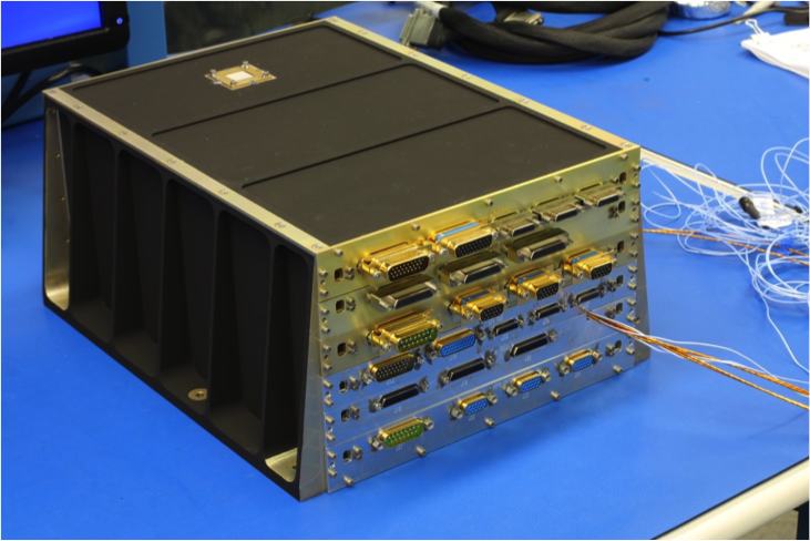
OVIRS is supported by a single electronics box containing three boards – a Low-Voltage Power Supply and a Command & Data Handling board that deliver regulated, filtered power to the instrument and control all instrument functions, executing commands and accepting housekeeping data. The third board hosts the System for Image Digitization, Enhancement, Control and Retrieval which controls all focal plane functions – analog-to-digital conversion, signal amplification, and detector clocking. All boards are functionally redundant.
In-flight calibration of OVIRS can use different sources. Spectral calibration will be completed with gratings that provide monochromatic scanned radiation with high repeatability while radiometric calibration is accomplished with blackbodies and flood sources as well as solar calibration via a dedicated calibration port. Dark currents will be assessed via dark sky observations.
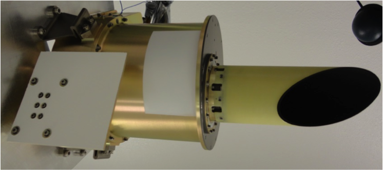
OTES – OSIRIS-REx Thermal Emission Spectrometer
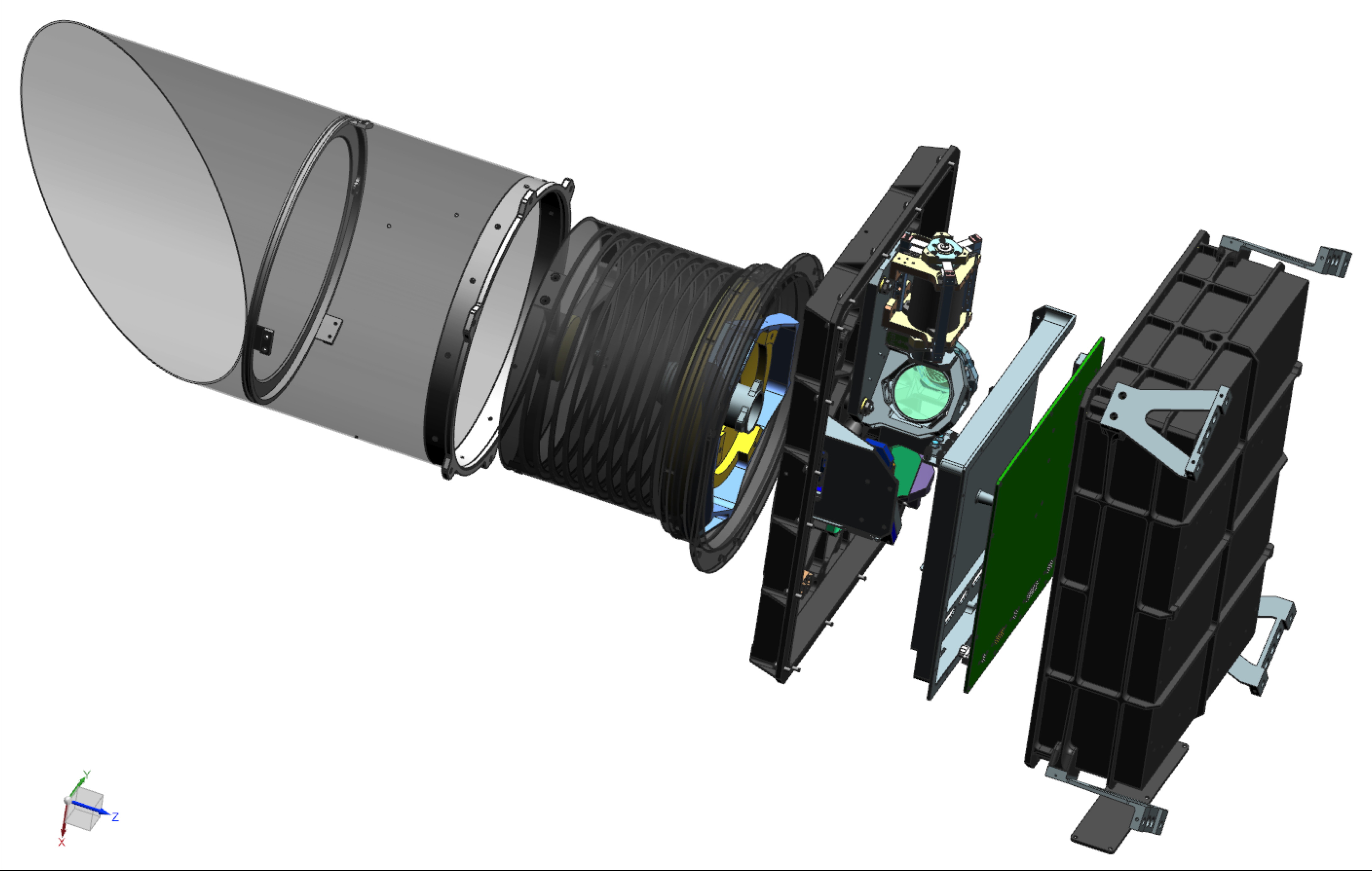
OTES, the OSIRIS-REx Thermal Emission Spectrometer, is the second spectrometer of the spacecraft covering the thermal infrared region of the spectrum to deliver complementing measurements to OVIRS to help mineralogical assessments, and to assess the thermal emission of the asteroid surface.
Like OVIRS, OTES is a point spectrometer – looking at a single point on the asteroid and using its and the spacecraft’s rotation to sweep out imaging strips. However, unlike OVIRS, OTES makes use of a Fourier Transform Interferometer with heritage from the OTES instruments on the Mars Global Surveyor and Mars Exploration Rovers.
The instrument was developed at the School of Earth and Space Exploration at Arizona State University.

Covering the 4 to 50-micrometer wavelength range, OTES can pick up fingerprint signatures of all major minerals expected to be found on Bennu and also delivers data on the water content of the minerals.
This spectral range also covers the bulk of thermal emissions from the asteroid which can yield valuable surface properties such as the mean grain size within the regolith.
The Fourier Transform Interferometer (FIT) is fed by a 15.2-centimeter Ritchey-Chretien telescope with a hyperbolic primary mirror and a hyperbolic secondary mirror to eliminate off-axis optical errors. The telescope arrangement creates a narrow instrument field of view of 8 millirad.
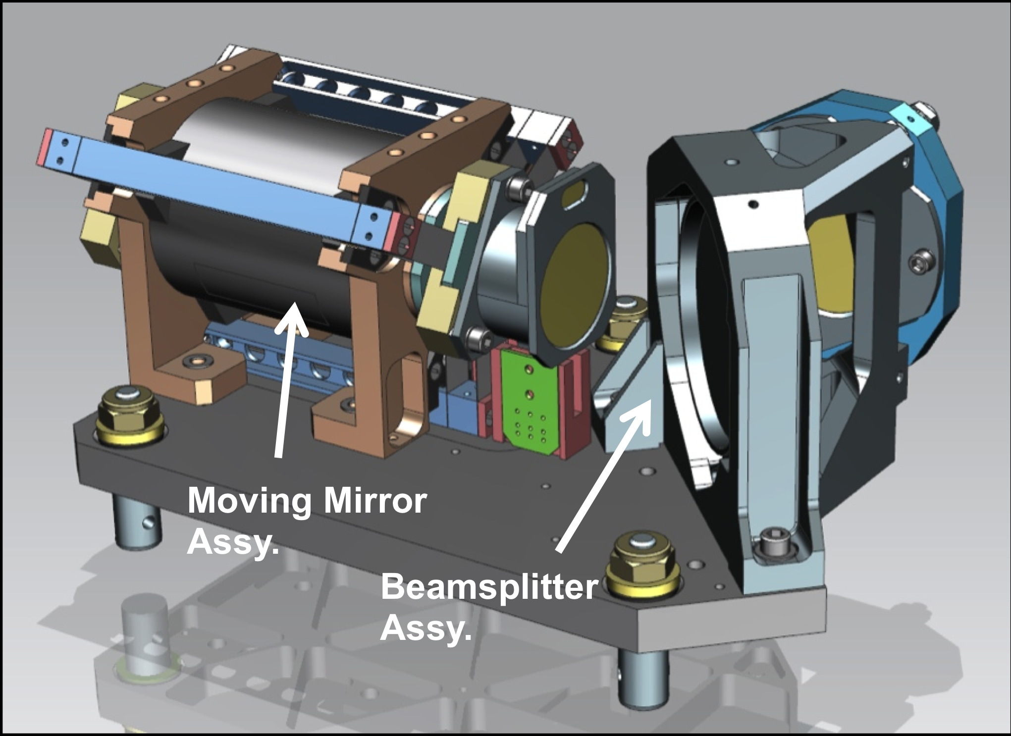
The basic working principle behind a Michelson Interferometer as used by OTES is splitting the incoming light with one half reflected off a fixed mirror and directed to the detector while the other beam is bounced off a translating mirror and then passed to the detector to introduce a time delay.
This will create optical interference on the detector which is different for each different time delay setting by moving the mirror – essentially converting the time domain into a spatial coordinate.
Fourier transform algorithms allow an entire spectrum to be reconstructed from many data points for the interference patterns at different mirror positions.
This spectrometer arrangement is more complex than traditional slit-type spectrometers or the design used by OVIRS, but yields a much higher resolution.
OTES uses a beam splitter made of chemical vapor deposited (CVD) diamond providing the stability and water resistance needed for the OSIRIS-REx mission.
The instrument captures one spectrum every two seconds and reaches a spectral resolution of 10cm^-1. Its spatial resolution depends on the distance of the spacecraft to the asteroid and varies from 40 meters at the 5-Kilometer surveying position to 4 meters for close reconnaissance passes.
OTES is an uncooled spectrometer system and features an optical baffle on its entrance to reduce the noise effects caused by solar radiation. Calibration is accomplished with an internal, conical blackbody target and dark space observation.
The OTES instrument electrics responsible for power supply, instrument control, and data read-out reside in an electronics box mounted directly under the spectrometer.
REXIS – Regolith X-Ray Imaging Spectrometer
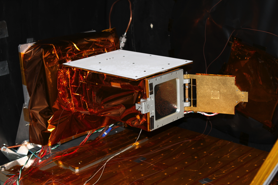
REXIS is the Regolith X-Ray Imaging Spectrometer and represents a student collaboration experiment that is the result of a joint venture between MIT and Harvard University. The instrument is tasked with the creation of a global X-Ray map of asteroid Bennu to enhance the mission’s remote-sensing capabilities.
The 4.4-Kilogram REXIS instrument measures the composition of the asteroid surface and the distribution of select elements through the measurement of soft X-Rays caused by solar-induced fluorescence. This observation complements the other two spectrometers of the OSIRIS-REx mission at a the high end of the electromagnetic spectrum.
REXIS can characterize the elemental abundances at the global scale down to a 50-meter resolution, allowing for an assessment of local variations in surface composition. Of particular interest for REXIS are magnesium, iron, sulfur and silicon which are a key focus point in the classification of meteorites.
Because REXIS relies on solar-induced X-Ray fluorescence for its measurements, the current state of the sun has to be known with high accuracy to extract elemental information from the X-Ray spectra – removing the effect of solar emission variability.
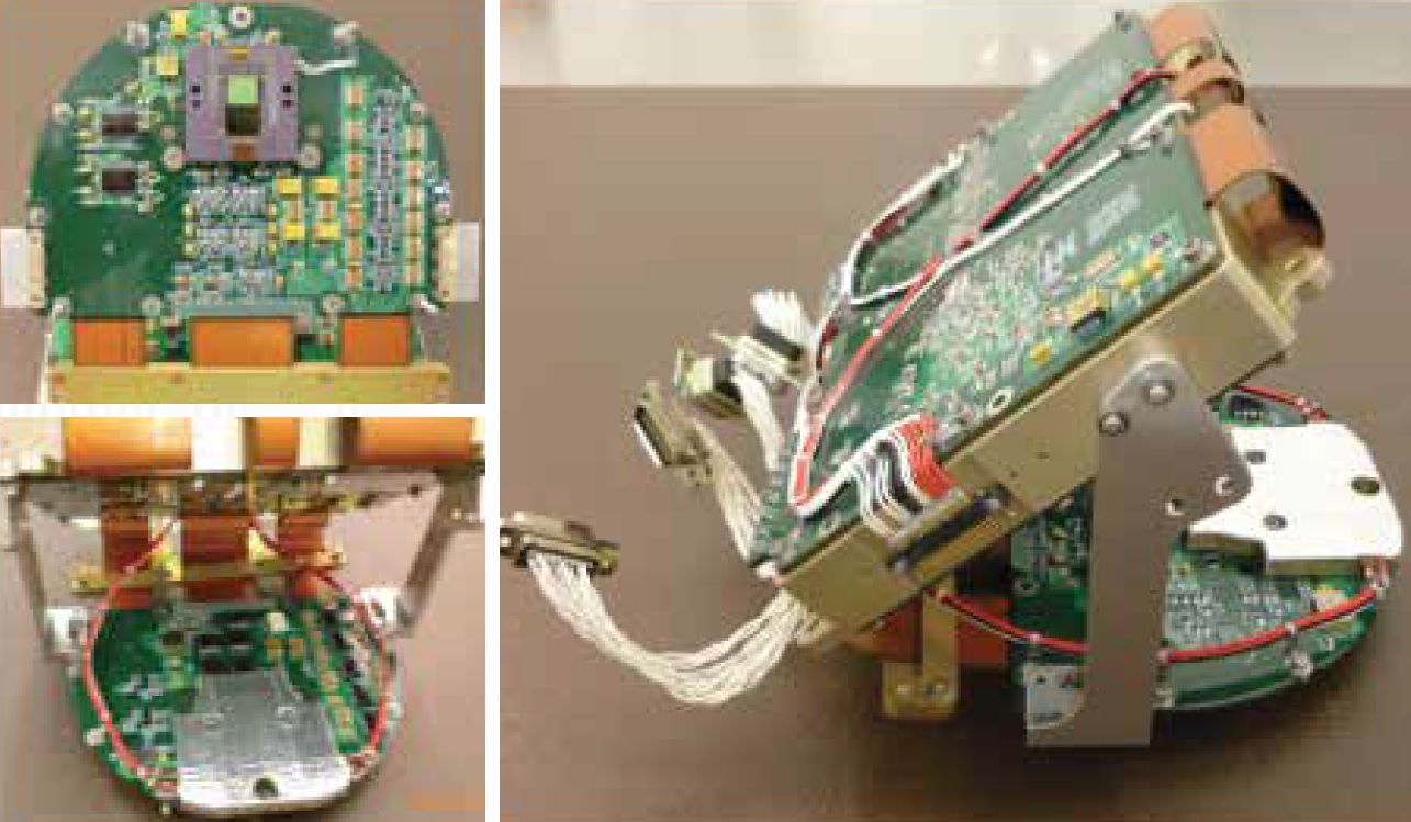
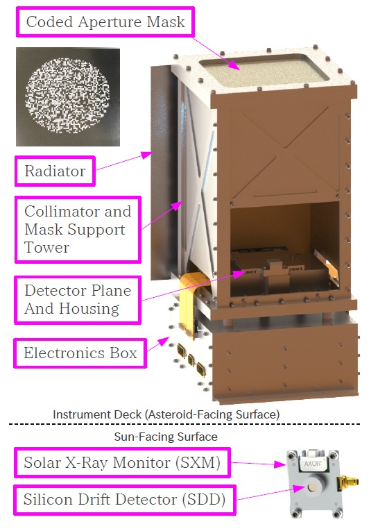
The REXIS instrument is comprised of three subassemblies, the Main Detector and Collimator Assembly, the electronics box and a Solar X-Ray Monitor installed on the sun-facing side of the spacecraft.
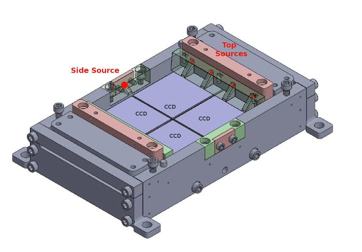
The Soft X-Ray Imaging Spectrometer is 32 by 14 by 20 centimeters in size and houses four Charged Coupled Devices in a 2 x 2 arrangement serving as the detectors of the instrument. The detectors reside underneath a Coded Aperture Mask with 64 pixels.
Imaging is accomplished by placing a pinhole mask over the detector array so that the shift in the shadow pattern can be put through a deconvolution procedure to encode the location of the X-ray source on the asteroid.
The instrument has a field of view of 30 degrees and reaches a spatial resolution of 5.6 meters when OSIRIS-REx is in the one-Kilometer orbit around Bennu.
The mask is placed 20 centimeters from the detector, sitting atop the instrument entrance. It is 100 micrometers thick and consists of stainless steel. Each of the 64 repeating pixels is 98.3 millimeters in diameter with a 1.5mm pixel pitch, creating an open hole fraction of 50%. Sitting atop the mask is a radiation cover that protects the detector during the lengthy cruise phase and opens at the start of the observation campaign at Bennu.

The detector module is 37 by 20 centimeters in size, hosting the four detector elements, Iron-55 calibration sources and electronics support systems for instrument readout.
Each of the four MIT-Lincoln Lab CCDs consists of 1024 by 1024 pixels and covers an energy range of 0.3 to 10 kilo-Electronvolt, though the instrument’s operational range is given as 0.5 to 7.5 keV. The energy resolution achieved by the detector is 130 eV.
Deposited atop the detector is a 220-nanometer layer of Aluminum responsible for optical blocking, only allowing X-rays to strike the detector.
When being struck by an X-Ray photon, the photo-effect in a CCD pixel will create free electrons that create an output signal when the detector is being read out. This signal – provided sufficient calibration information is available – can be translated into the energy the photon possessed when striking from which the material that emitted the photon can be deduced.
The REXIS CCD is operated at a fixed integration time of four seconds and employs two frame store areas, read out by one of four output nodes on each CCD. Digitization is completed by a 12-bit analog to digital converter and the instrument converts the images to event lists with time tags, reducing the downlink data volume by orders of magnitude as only frames with data will be sent to Earth. Another measure to reduce data volume is binning pixels in an 8 x 8 array to super pixels 0.192 millimeters in size.
While a collimator-based instrument could achieve an angular resolution of 28 centimeters, REXIS’ maximum resolution from 730 meters will be lower by a factor of 7.3 taking into account the integration time of the instrument, spacecraft and asteroid motion, and limitations in the coded-mask design.
Calibration of the detector is accomplished with a source of Iron-55 placed around the CCD to fully saturate the detector with photons at an energy of 5.89 keV. Measuring the detector gain for a well known and calibrated X-Ray energy allows the instrument to determine the energy of any other photon.
Another calibration technique is measuring the cosmic background simultaneously with imaging operations since the asteroid will not occupy the entire field of view, allowing the background to be measured on the detector edges.
The measurement of the solar X-ray spectrum is accomplished by a separate Solar X-Ray Monitor SXM because the highly variable input from the sun has to be tracked for all asteroid measurements to be able to calculate the fluorescence energy emitted by the different elements.
SXM is installed on the side of the spacecraft facing the sun when REXIS is in nadir-pointed observation mode.
The heart of SXM is a commercial-off-the-shelf Silicon Drift Detector (SDD) provided by Amptek with a custom read-out circuit. The detector has a 25mm² active area with a detection depth of 500 microns. It is housed in an 0.5-millimeter thick Berryllium housing for optical blocking. A thermoelectric cooler is necessary to keep the detector at under 0°C while in direct solar illumination.
SXM covers an energy range of 1 to 20 keV with an energy resolution around 125 eV at 5.9keV.
The solar X-Ray spectrum can vary greatly on time periods of only ten minutes up to several days with flux variation up to three orders of magnitude, requiring constant SXM readings to put the main spectrometric measurements into context.
The main spectrometer of REXIS is thermally decoupled from the main spacecraft structure and hosts a radiator pointed towards deep space when in observation attitude to be able to cool the focal plane to below -60°C. In a typical orbit around the asteroid, taking 27 hours for one lap, OSIRIS-REx will be nadir-pointing for at least 11 hours for operation of the remote sensing instruments.
Gravity Science
To reveal the interior structure of Bennu, OSIRIS-REx makes detailed measurements of the planet’s gravitational field which will point to internal structures down to the core.
Like many other planetary missions, OSIRIS-REx will use its radio system to conduct sensitive measurements using Deep Space Network (DSN) Doppler, and Delta-DOR
(delta – Differential One-way Ranging) techniques. Radio science can yield a detailed gravity field measurement, accurate mass estimate, asteroid ephemeris and other physical characteristics of asteroid Bennu.
Local variations in gravity can act on the spacecraft in orbit and cause it to speed up or slow down – those changes in spacecraft motion can be detected using the Doppler Shift in the X-band transponders used by the radio sub-system. For the gravity experiment, the High Gain Antenna needs to be pointed directly at Earth so that Ranging Signals can be sent and received at the Deep Space Network Stations.
Turnaround ranging using the Deep Space Network involves the DSN station that sends a signal to the spacecraft containing ranging tones that it imposes on a carrier using phase modulation. When the spacecraft receives the tones, it sends them right back via X-Band downlink. The DSN station records the timing of the ranging tones uplink and the timing of the tone’s reception order to calculate the line-of-sight distance to the spacecraft.
After processing of the data taking into account delays by the electronics on the spacecraft and the ground, atmospheric and ionospheric properties, interplanetary plasma, and relativistic effects, the ranging method achieves sub-meter accuracy.