
LISA Technology Package (LTP)
The LISA Technology Package was developed for the European Space Agency by a consortium of international institutions from France, Germany, Italy, The Netherlands, Spain, Switzerland and the United Kingdom – each providing components and subsystems for integration by the prime contractor Airbus Defence and Space (formerly EADS Astrium).
Within LTP, a one-million Kilometer arm of the eLISA mission is shortened to 38 centimeters to fit the two test masses into a single spacecraft while still being able to conduct measurements applicable for eLISA. The two test masses serve two roles – they function as mirrors for the interferometer and as inertial reference sources for the Drag Free Control System.
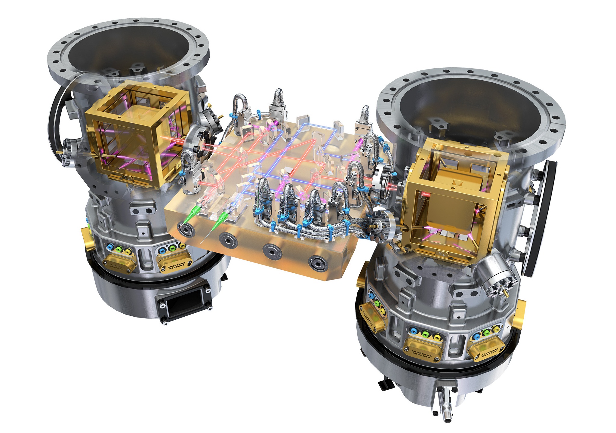
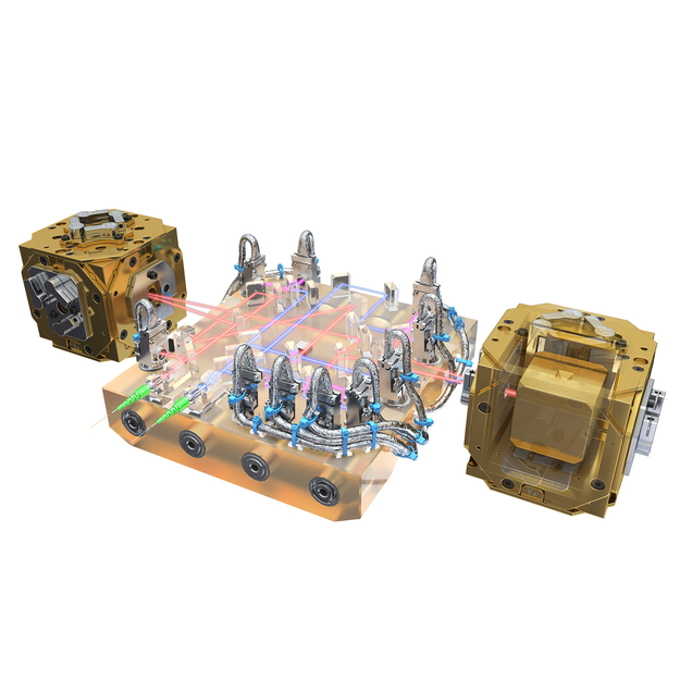
The measurement principle of LTP centers around the two test masses, each housed in a sensor cage that is rigidly attached to a highly stable optical bench. Two measurements are made for the determination of the position of the two test masses – laser interferometry measures only the precise distance between the masses along one sensitive axis while an electrostatic sensing system can measure the position of each test mass within its experiment chamber.
The distance between the two masses is measured by an optical metrology system, i.e. laser interferometer. Measurements are made along the sensitive x-axis which forms the nominal line of connection between the two masses. Each of the identical test masses consists of a gold-platinum alloy with a mass of 1.96 Kilograms and a side length of 4.6 centimeters – the same specification will be in place for the eLISA mission. The mono-phasic alloy used by LISA Pathfinder is formed from 73% gold and and 27% platinum and was chosen for its extremely low magnetic susceptibility and high density which reduces the effect of external forces on the masses. The nominal separation distance between the two masses is 37.6 centimeters.
The LISA Test Package payload has a mass of 125 Kilograms, is 64 by 38 by 38 centimeters in size and requires 150 Watts of power when in operation.


Hosted on the optical bench are four interferometers – one to accurately measure the distance between the test masses, one to determine the distance of one of the test masses to the optical bench, and the other two to measure the residual frequency noise of the lasers. The measurement of the distance between the masses and the distance of one mass to the spacecraft is identical to the local measurement of eLISA and thus provides an in-flight demonstration of the precision laser metrology system that can be directly applied for eLISA.
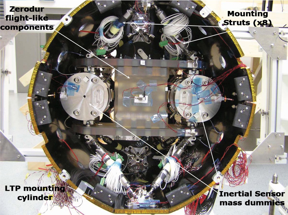
The optical bench itself consists of Zerodur, a highly-stable glass offering an extremely low expansion with temperature. The optical components are attached to the optical bench using hydroxyl-catalysis bonding that ensures a long-term stability in their position. Both test masses are enclosed in a vacuum chamber pumped down to pristine vacuum conditions.
A challenge for the LISA Pathfinder mission is control and stabilization of the test mass relative coordinates, coupled with the spacecraft, representing a 15-degree-of-freedom system. When in science mode, after initial stabilization, the non-gravitational acceleration along the x-axis has to be minimized.
The LTP can be seen as consisting of two functional subsystems, the Inertial Sensor Subsystem ISS, and the Optical Metrology Subsystem OMS, both controlled by the Data & Diagnostics Subsystem. The ISS provides all means necessary to bring the test masses to space and then control the test mass attitude and position through electrostatic actuation and suspension so that one test mass is in free fall towards the other while the spacecraft reduces external disturbances.
The ISS contains a number of components – the test masses, electrode housing, Grabbing, Positioning and Release Mechanisms, the launch lock, a UV discharge system, vacuum systems and all associated subsystem electronics.
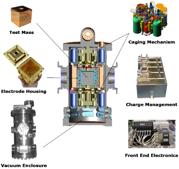
The two Inertial Sensor Subsystems each measure 43 centimeters in height and 18 centimeters in diameter, consisting of a titanium housing since no magnetic components can be part of the structure. Additionally, the structure must be perfectly aligned and maintain this alignment when subjected to the extreme acoustic and vibration environments of launch. Special feed-throughs in the titanium housing are used for electrical connectors and UV fibers.

All materials within the ISS must have low-outgassing characteristics to preserve the vacuum within the chamber. A Caging and Venting Mechanism functions as a launch lock and can also vent any gas within the ISS into space to preserve the vacuum.
For launch and transfer operations, the two test masses are held in place by a Grabbing, Positioning and Release Mechanism that holds the masses with a force of 1,200 Newtons without damaging the gold-coated surface. The mechanism consists of a three-stage capture design – a single-shot actuator holding the mass in place, a second stage actuator that can break the adhesion to the launch lock and a release actuator breaking the adhesion of the second stage positioning plunger.
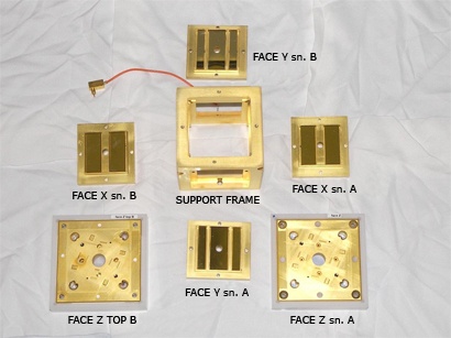
When set free, the masses can be positioned within the test chamber through the use of electrostatic forces. Each test mass is surrounded by parallel sets of electrodes that measure the mass position and orientation relative to the spacecraft. This measurement can be made as a function of the varying capacitance between the electrodes and the test mass itself. The capacitive sensor comprises a cubic molybdenum housing with gold-coated molybdenum electrodes. In the nominal position, the mass will be located 4 millimeters from all electrodes. This gap was chosen in a trade-off between the magnitude of noise due to uncontrolled potentials and the sensing requirement for the capacitive measurement.
The same electrodes are used to apply electrostatic forces to the proof masses. Capacitance variations are read out by a front-end electronics set composed of high-accuracy differential inductive bridges excited at 100kHz and detected using a phase sensitive detector assembly. Opposite electrodes are coupled by a capacitive bridge and a shift in the position of the test mass will yield a differential bi-polar signal.
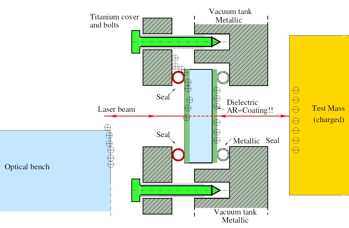
Laser light for the interferometry measurements can enter the ISS chamber through optical windows. Within the chambers, a UV injector can be used to provide ultraviolet radiation for photoelectron extraction that is employed to neutralize the charge on each test mass which may build up due to cosmic rays.

The charge on the mass is measured by commanding the mass to rotate with a given amplitude and measuring actual displacement of the mass. The difference between the commanded and actual displacement allows the test mass charge to be calculated. The UV radiation source is a mercury vapor lamp coupled to an ultraviolet optical fiber that relays the radiation into the chamber. The system can operate in a rapid discharge mode in which the science run has to be stopped and the UV lamp is commanded to its most intense setting. A second mode of operation allows science to continue while a slow, balanced discharge is completed to keep the mass at neutral charge.
Further measures to eliminate known error sources include the placement of balance masses inside and outside the vacuum enclosures in order to zero-out the differential gravitational forces and gradients at the test masses. Also, the thermal environment of the test masses is precisely controlled to create a thermally quiet environment with extremely slow variations, if any.

The Optical Metrology Subsystem OMS serves as the high-precision optical sensing system needed to measure the differential movement of the two test masses and the movement of one test mass with respect to the spacecraft. The system is based on heterodyne Mach-Zender interferometry with pico-meter accuracy. OMS is comprised of the Reference Laser Unit, Acousto-Optic Modulator, an Optical Bench and a Phasemeter.
The interferometer system makes a total of four measurements:
Heterodyne measurement of the relative position of the test masses along the sensitive x-axis
Heterodyne measurement of the position of proof mass 1 relative to the optical bench
Differential wave-front sensing of the relative orientations of the proof masses around the y and z-axes
Differential wave-front measurement of the orientation of proof mass 1 with respect to the spacecraft y and z-axes.
All sensitivities are in the range of 10 picometers for displacement and rotation.
The light source for the interferometer is a Nd:YAG non-planar ring oscillator delivering infrared light at a wavelength of 1,064 nanometers and a power of 35mW. Coming from the laser source, the beam is split and each partial beam is run through an Acousto-Optical Modulator Unit to achieve the necessary frequency shift – one modulator is operated at 80 MHz, the other at 80.1MHz, creating two beams with a frequency difference of around 1kHz which is the heterodyne frequency of the interferometers. The light is then passed though the optical pathlength difference actuators in place to stabilize the fiber optic paths to the optical bench.
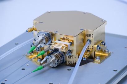
The infrared light is routed to the optical bench using polarization-maintaining optical fibers and injectors to allow the two beams to enter the four interferometers to make the four measurements listed above.
The first interferometer measures the differential motion between the masses, the second provides the position and angles of the x1 mass, the third employs an unequal arm Mach-Zehnder interferometer to measure frequency fluctuations in the laser beam, and finally the Reference interferometer that uses a rigid equal arm interferometer to provide a measurement of system noise.
Furthermore, the light from each beam is directed to a photodiode to monitor noise in the laser intensity. Feedback from the last three measurement systems mentioned here is used to stabilize the frequency, the fiber pathlengths in the optical pathlength difference actuator, and the laser intensity output.
Detection of the interferometric signals is accomplished with quadrant photo-detectors which permit the measurement of the yaw and pitch of the masses relative to the sensitive x-axis. The phasemeter detectors operate at a frequency of 100 Hz and signals are put through Discrete Fourier Transformation to yield the phase signals at the heterodyne interferometer frequency, outputting the longitudinal phase from the four interferometers plus differential wavefront sensing. The LPT data processing system will down-sample the raw 100Hz output to 10Hz before transmission to the onboard computer for data storage and downlink.