
Field Effect Electric Propulsion Subsystem FEEPS
FEEPS was originally planned to fly on the LISA Pathfinder Mission, but was replaced by a Cold-Gas Microthruster System because the FEEP system was not ready in time.
The following is a description of FEEPS based on its planned design:
The LISA Pathfinder spacecraft has to permanently follow its proof masses in their free fall within a closed-loop control scheme called drag-free control. The position of the proof mass relative to its nominal location is measured by the gravitational reference sensor and a high-gain control loop will try to null this error by forcing the spacecraft to follow the proof mass and keep it in its neutral position. The necessary force is imparted on the spacecraft by a set of micro-thrusters.
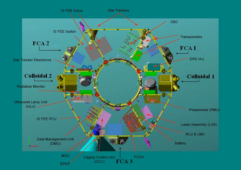
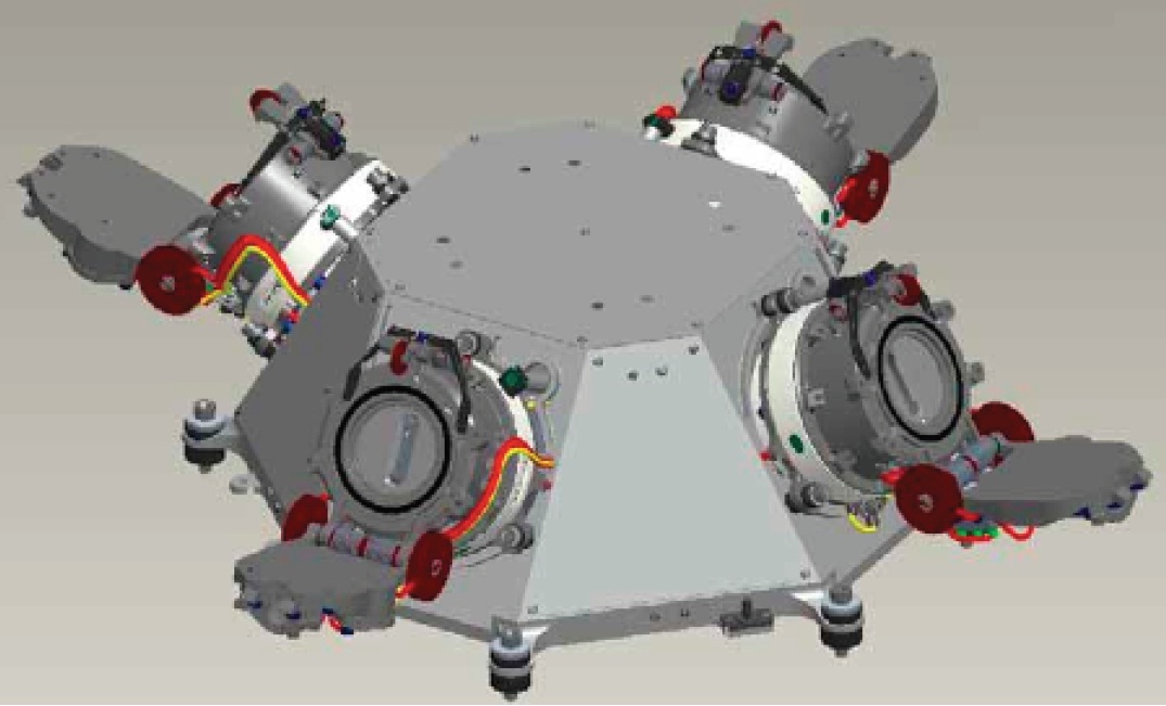
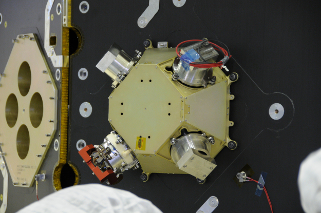
The Micro Propulsion System MPS of the LISA Pathfinder consists of three main subsystems known as the Micro-Propulsion Assemblies MPAs, each comprised of a FEEP Cluster Assembly, a Power Control Unit and a Neutralizer Assembly.

The system is designed to deliver stable and commandable thrust levels from 0.1 to 150 micro-Newtons with a thrust setting accuracy of 0.1 micro-Newtons and a time response better than 200 milliseconds for any thrust step. Furthermore, to comply with the strict requirements of the LISA Pathfinder, the propulsion system does not have any moving parts that could disturb the spacecraft, nor any gas leaks that could generate thrust along one spacecraft axis. Additionally, no ferromagnetic materials are part of the system to prevent a magnetic disturbance of the test masses.
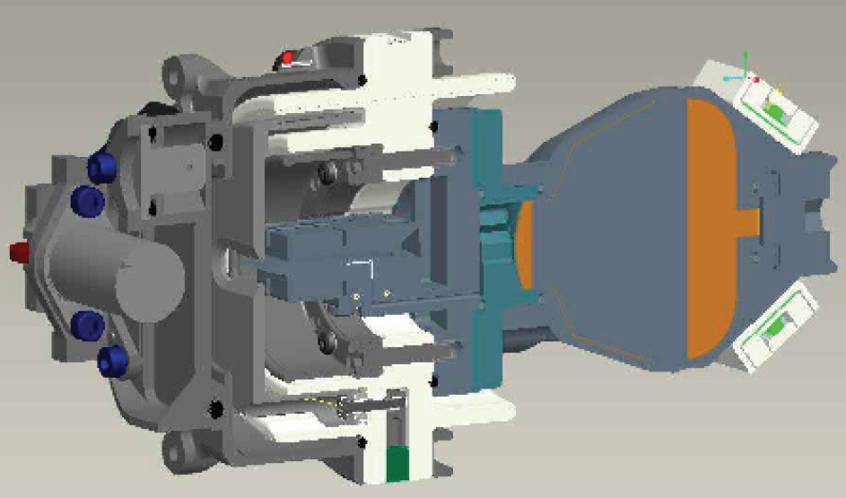
The three Micro-Propulsion Assemblies are facilitated on the external panels of the Science Module of the LISA Pathfinder spacecraft, spaced by 120 degrees to be able to deliver redundant three axis control. Each FEEP Cluster Assembly includes four thrusters that can be commanded individually and work in hot redundancy. They are mounted in an arrangement that allows the thrust vectors to be placed to maximize the spacecraft positioning in all directions. Each thrust vector has a 45° azimuth and 30° elevation to the nominal. Within the spacecraft resides the Power Control Unit while the thrusters and Neutralizer Assemblies are external components.
The Neutralizer Assembly is a self-controlled unit comprised of two Neutralizers installed on a support structure with all necessary interfaces including electrical connectors, thermal couplings and mechanical structures. The neutralizer is an essential component necessary to nullify the spacecraft surface potential when the ion thrusters are operating. The neutralizers operate in a cold redundancy scheme.
The Power Control Unit interfaces with the spacecraft power systems as well as command and telemetry systems and delivers power to the FEEP Cluster and Neutralizer Assemblies.
Two different Micro-Propulsion Technologies are being used by the LISA Pathfinder Mission as part of an assessment of which is most suitable for in-space application. The two different thruster emitter technologies are known as slit-shaped emitter using Caesium as propellant, and needle-shaped emitter with Indium propellant.
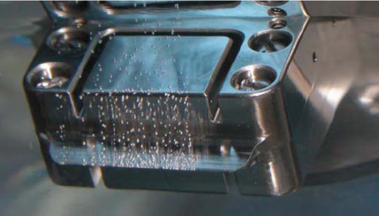
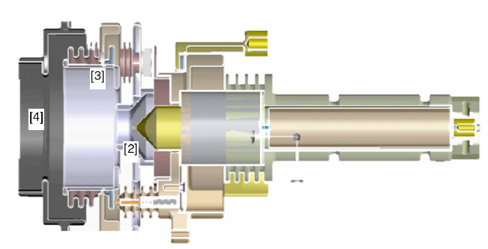
The slit-shaped emitter design generates field emission by applying an electrical field on the liquid Caesium metal heated above its 29°C melting point inside the edge of two sharp blades that make up the emitter slit. A Taylor cone is formed in the equilibrium between the surface tension of the liquid and the electric field strength creating a jet protruding outward due to space charge. At the tip of the jet, atoms are ionized and accelerated by the existing electric field. This configuration permits the formation of multiple emission sites along the length of the slit based on the commanded thrust level, meaning that the operational thrust range can be extended very easily, simply by increasing the slit length.
The Caesium ions are ejected at a velocity of 100km/s, requiring an electric field voltage between 7 and 13 kilo-Volts. Using metal ions allows the FEEP FT-150 thruster to reach substantially higher specific impulses than conventional ion thrusters that use gas ions. The impulse created by the system varies between 3000 and 5000 seconds based on operating conditions. The FT-150 FEEP thruster assembly has a mass of 1,400 grams, including 92g of propellant per thruster. It requires 6 Watts of power and can deliver a thrust of 0.1 to 150 micro-Newtons with a thrust resolution better than 0.1 micro-Newton at a thrust response time of 50 to 150 milliseconds.

The FFEP thruster employing the needle-shaped design uses a similar principle in which Indium is heated above its melting point of 156°C in a needle shaped configuration. Applying an intense electric field will liberate Indium ions that can be accelerated to generate thrust. In this configuration, each needle can only host one emission site which means that several needles are required to form a thruster with suitable thrust range. LISA Pathfinder requires nine needles per thruster. The advantage of this system is that the Indium fuel can be more easily managed than the more reactive Caesium. The needle-shaped system reaches a similar performance as the slit-shaped emitter-based thrusters, though electrical power required by the needle-shaped design is somewhat higher.
The Neutralizer Assemblies, each with two neutralizers for redundancy, are installed on the adjacent side panels to the thrusters. They operate at a bias voltage up to 200 V to enhance electron emission, taking into account the low-plasma environment at the L1 Lagrange Point.
The Power Control Unit of the thruster system is in charge of accepting commands from the payload computer to command the individual thrusters at any thrust setting in their operational range at the expected resolution of <0.1 micro-Newton. Four independent FEEP thrusters can be controlled at any one time with the PCU delivering a voltage of up to 13.7kV. It also delivers power to the neutralizers.
The Power Control Unit can reach emitter voltages up to 13.7kV at low currents up to 2mA corresponding to an emitter power of 18 Watts. An accelerator can deliver voltages from –1 to –1.7kV and currents up to 1mA corresponding to an accelerator power of 1.7 Watts. For thrust regulation, the PCU delivers two High-Voltage supplies to each thruster operated in a closed control loop.