
HTV-KITE Experiment

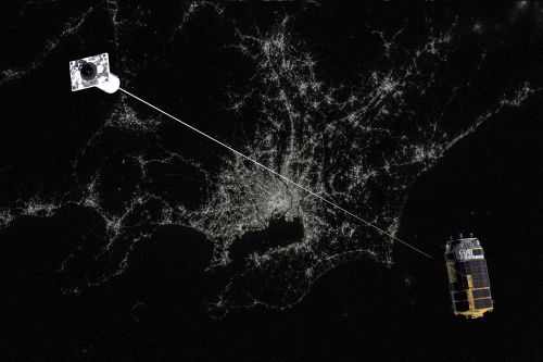
KITE – the Kounotori Integrated Tether Experiment – will be held for one week after Japan’s HTV-6 cargo craft undocks from the International Space Station with the spacecraft releasing a 700-meter long Electrodynamic Tether with a 20-Kilogram end mass to study the feasibility of the use of such tethers for in-space propulsion and space debris removal.
Electrodynamic Tethers (EDTs) have been a part of different satellite missions to evaluate a number of applications including electric generators, propulsion systems, and space debris removal. Other uses of Electrodynamic Tethers include Ultra Long Frequency communication antennas, attitude stabilization and variable gravity experimentation.
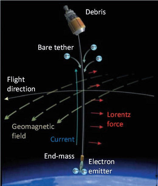
The KITE-EDT is a bare-wire-tether intended to collect electrons and act as a field-emission cathode for the release of electrons – an arrangement that could provide complete propellant-less propulsion for deorbitation of spacecraft as part of Active Debris Removal. KITE will be deployed for a seven-day test sequence after HTV-6 departs the Space Station ahead of jettisoning the tether before heading into end of mission operations, i.e. deorbit burn and re-entry.
Studies have shown, that if five large pieces of debris are removed from crowded orbits, a cascading increase of the population of smaller debris (through collisions between debris pieces) can be halted. Removing five pieces of debris per year is not an unrealistic goal for Active Debris Removal missions and the KITE project proposes attaching EDTs to debris pieces to bring them to a swift re-entry.
There are a number of advantages of EDTs over other Active Debris Removal proposals, first and foremost the fact that they require no propellant and only very little electrical power because the electromagnetic force generating the thrust component is created by the tether current’s interaction with the geomagnetic field. Also, EDT-based systems require no active guidance in the form of thrust vectoring and no attention has to be paid to the mass characteristics of the debris piece.
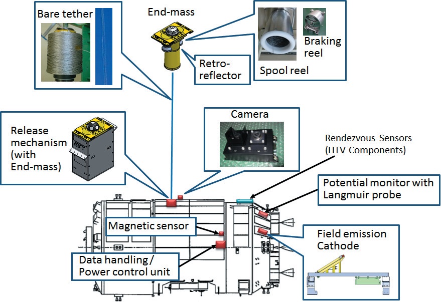
The KITE Experiment comprises a number of external components on the HTV – the tether with its end mass, the releasing mechanism, a camera to monitor dynamics within the KITE-HTV complex, an Electron emitter, Plasma & current monitor, magnetic sensor and a Power & data handling unit.
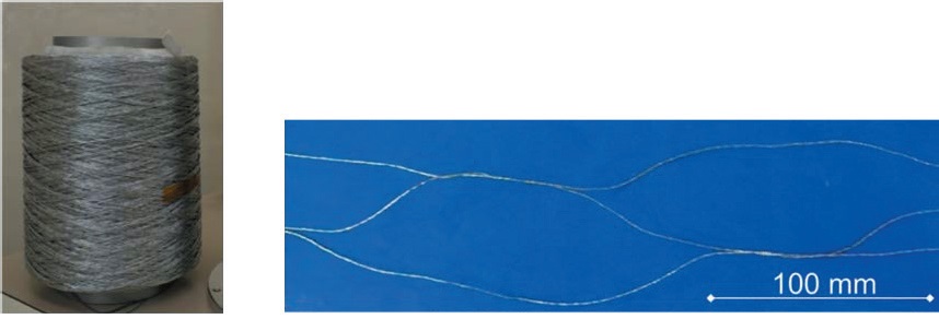
The KITE Tether has a total length of 720 meters and consists of a thin aluminum and stainless steel wire coated by a material possessing favorable electrical conductivity.
The individual tether yarns have a mesh structure to avoid the tether being severed by small-sized space debris & to optimize electron collection. The tether is rolled up and housed within the end mass of the EDT system with the last ten meters of the tether connected to a braking reel that introduces a mechanical friction to bring the deployment to a graceful stop instead of an abrupt stopping point that would cause rebounding or severing of the tether.
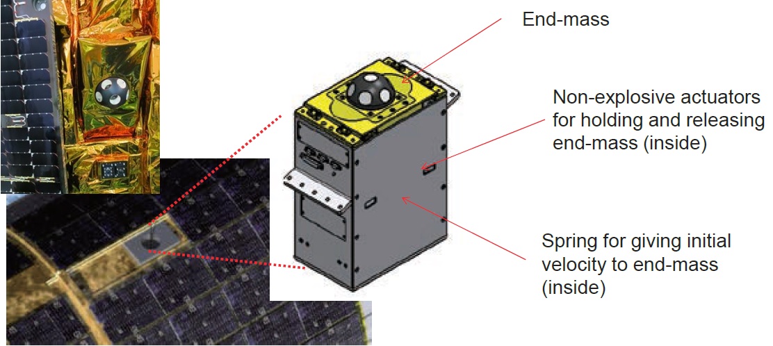
The End Mass Release Mechanism comprises a loaded spring and non-explosive separation actuators that firmly hold the mass in position for launch and the mission to ISS with three commands needed to execute the release to ensure no premature End Mass Release occurs in any of the critical mission phases. Once released, the End Mass is accelerated to a speed of 1 meter per second by the loaded spring.
The motion of the end mass during deployment and free flight is observed and analyzed by a camera installed on the exterior of the HTV as well as the spacecraft’s rendezvous sensors that are primarily for the link-up with the Space Station. The end mass hosts reflectors which make it visible to HTV’s LIDAR that bounces pulses of laser light off its target to determine its relative position to the spacecraft. The maximum tether length was determined by the capabilities of the rendezvous sensor to ensure the mass can be monitored throughout the test mission.
The camera is installed adjacent to the release mechanism and comprises two optical systems and CMOS detectors, one for the observation of the mass at close range just after separation and the other with a wide-angle lens to monitor the mass when the tether is fully extended. Onboard processing of imagery with features such as point recognition and image trimming reduces the volume of camera data that needs to be downlinked.
While the EDT used on HTV-6 is capable of collecting electrons from the ambient space plasma, the system includes an electron source for testing purposes.
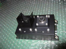
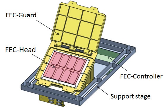
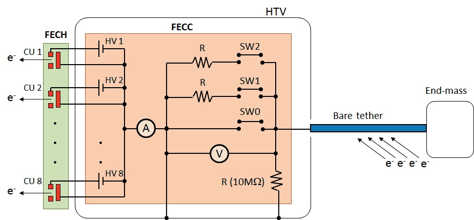
Installed on the exterior of HTV’s propulsion module is a Field Emission Cathode (FEC) to serve as a low-power and light-weight electron emitter. FEC consists of the FEC-Head which is responsible for emitting electrons into the ambient plasma, the FEC-Controller that generates the high-voltage power supply for the Head, and the FEC-Guard acting as protective element for the head. The Guard opens before the electron emission sequence begins on Day 3 of the experiment.
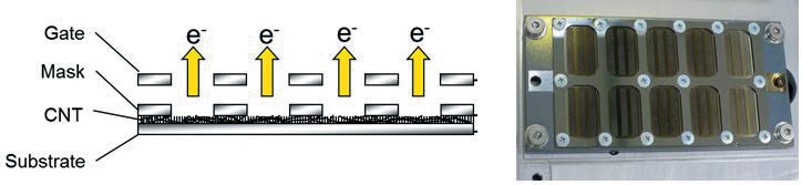
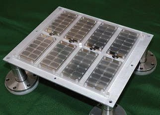
The FEC-Head facilitates eight carbon nanotube cathodes along with their connectors and a mechanical chassis. Each cathode interfaces with its own high-voltage DC converter to supply the high voltage needed for the emission of electrons. Carbon nanotubes have been selected because of the lower extraction voltage with an emission current of 2.2mA at a gate voltage of 560 V.
One item of interest for the KITE experiment is monitoring the degradation of the carbon cathodes by atomic oxygen abundantly present in the low orbit regime. As a result of degradation, the voltage applied to the cathodes will have to be increased to maintain a constant emission current. KITE’s high-voltage supplies can deliver up to 900V, permitting a study of degradation characteristics for future operational debris removal missions.
The cable from the tether is connected to the FEC Controller through three relays to avoid a discharge failure with measurement of voltage and current occurring within the FEC-C. Eight High-Voltage Power Supplies drive the cathode units so that the gate voltage on each cathode can be set individually.

An electrical potential monitor with a Langmuir probe is installed on the propulsion module of the HTV to measure the electrical potential of the HTV spacecraft body with respect to the ambient plasma environment. This measurement is critical for the determination of the end-to-end tether voltage which corresponds to the sum of the absolute electrical potential of the HTV and the tether voltage measurement in the FEC Controller. A large planar probe measures the electron saturation current of the ambient plasma to estimate the number densities of the plasma environment experienced by HTV.
A magnetic sensor installed on the main body of HTV measures the magnetic flux density of the geomagnetic field to help in the study of EDT charging dynamics.
The first day of KITE operations is dedicated to the deployment of the Electrodynamic Tether and a tether motion stabilization carried out by HTV firing its attitude control thrusters. Detailed monitoring of tether dynamics is planned for the second day as well as the measurement of the electromotive force without any active electron emission from the spacecraft. The Field Emission Cathode is powered up in Day 3 and measurements of HTV’s electric potential are made with and without active electron emissions.
Day 4 is dedicated to measurements of the electric potential and current under constant electron emission by the cathode followed by stepping the system through different settings on Day 5. Electron Emission will be set to the maximum possible level (up to 10mA) on Day 6 to make a measurement of the thrust generated by the Lorentz force created by running a current through the length of the tether in Earth’s magnetic field. The resultant thrust should be on the order of 0.1 Newton and will be measured as a function of tether vibration. On the final day of operations, KITE can repeat any experiments for additional data gathering before the tether is cut and HTV-6 enters is standard end of mission operations with the tether expected to decay naturally.