
HTV-6 Cargo Overview

HTV-6 is the sixth mission of the H-II Transfer Vehicle operated by the Japan Aerospace Exploration Agency and currently the largest resupply craft servicing the logistics needs of the International Space Station. The mission delivers approximately 5.9 metric tons of cargo comprised of 3.9t of cargo in the Pressurized Logistics Carrier and 1.9t in the Unpressurized Logistics Carrier.
Highlights of the HTV-6 mission include the delivery of the first batch of new Lithium-Ion batteries to replace the aging Nickel-Hydrogen batteries that ISS currently relies on to deliver power when the solar arrays are not illuminated by the sun. HTV-6 is also planned to execute a secondary mission after its cargo-delivery to ISS dedicated to testing a 700-meter long tether in space that can generate a small thrust through electromagnetic dynamics and might build the foundation for future debris deorbiting systems to reduce the growing population of space debris.
Pressurized cargo delivered by HTV-6 comprises the typical mix of crew supplies (food, clothing, hygiene equipment), maintenance hardware for ISS, water, and utilization payloads. Some key items onboard HTV-6 are discussed in detail below.
HTV-6 again pushes the record for the number of Cargo Transfer Bags (CTBs) facilitated aboard any HTV to date due to continued improvements made to packing of individual bags. In total, HTV-6 can transport 248 CTBs to ISS, 92 of which can be loaded as part of the late cargo loading procedure available until 80 hours prior to liftoff. For reference, the first HTV mission carried 208 bags with capacity sequentially increasing to 230 CTBs for HTVs 2, 3 and 4, and 242 CTBs on HTV-5.
The internal cargo delivered by HTV-6 is comprised of 1,264 Kilograms of crew supplies (food rations, 600 liters of water, clothing, hygiene equipment & consumables), 663kg of maintenance hardware, 420kg of utilization payloads, 156kg of computer resources, 35kg of spacewalk equipment, and 28kg of Russian cargo.
New Power for ISS


HTV-6 is the first in a series of HTV missions dedicated to taking new Lithium-Ion batteries to the International Space Station to replace the Nickel-Hydrogen batteries that have been installed on the Station’s truss segments since they were launched over the course of the early 2000s. Approaching the end of their operational lives, the Ni-H batteries are being replaced with higher-capacity Li-Ion batteries to allow ISS to head into the next decade of operations.
The Unpressurized Logistics Carrier of HTV was reinforced to support a payload mass of 1,900 Kilograms, an increase over the 1,600kg for previous missions. Riding as cargo upmass are six Li-Ion Battery Orbital Replacement Units, each with a capacity equivalent to two of the current Ni-H batteries – allowing the six new batteries to replace twelve old ones. Nine of the 12 replaced batteries will be installed on the Exposed Pallet of HTV to be disposed of via destructive re-entry while the three remaining ones will stay on ISS for the time being.
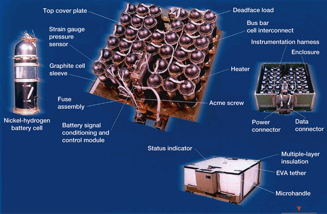
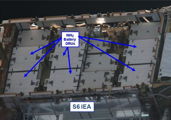
Prior to the replacement effort, the International Space Station hosts 48 Ni-H batteries installed in four locations known as the Integrated Equipment Assemblies which reside on the S4 & S6 Starboard Truss Segments and P4 and P6 Port Trusses. Each IEA is responsible for two of the Station’s power channels and facilitates two solar arrays, the Photovoltaic Thermal Control System, shunt units, batteries, and DC converters and switching units that pass power inboard for distribution to the Station’s Systems.
The Ni-H batteries in use over the Station’s early life each weigh 169 Kilograms and are 104 by 94 by 48 centimeters in size, hosting 38 in-series connected battery cells with a total storage capacity of 81 Amp-hours per battery set. They were built for a 6.5-year lifetime and 38,000 orbit cycles which they surpassed by a significant period of time.
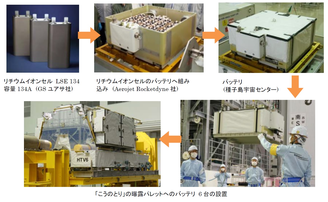

Studies for the replacement of the Ni-H batteries with Li-Ion-based technology began in 2009 and continued until late 2011 when the design, development and fabrication was green-lighted by the ISS program. Cell Safety Testing and Qualification was underway in the first half of 2012 with GS Yuasa’s LSE-134 Li-Ion cells being selected for the battery ORUs. NASA and prime contractor Aerojet Rocketdyne finished the Critical Design Review for the batteries in November 2013 and the first batch was delivered to NASA in March 2016.
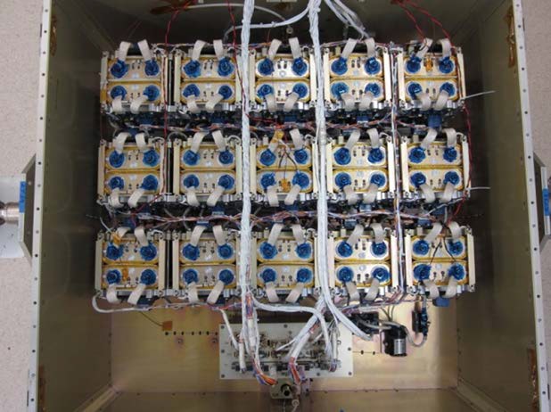
The Li-Ion Battery ORUs host 30 LSE134 cells in series, each 5 by 13 by 26.3 centimeters in size with a mass of 3.53 Kilograms and a capacity of 134 Ah at a voltage of 3.7V. Ten cells are facilitated within a single pack with Radiant Barriers installed between pairs of cells and the three packs are installed at a spacing of nine centimeters.
All 30 cells have individual thermal and voltage monitors and two independent controllers protect the batteries against thermal runaway. Fault isolation is possible at the individual cell level as another safety measure to reflect recommendations made for the Boeing 787 batteries that suffered from thermal runaway issues and are similar in design to the ISS battery ORUs. As a last layer of protection, the batteries include vents and flame traps to be able to tolerate the failure of individual cells.
The Li-Ion Battery ORU is 104 x 94 x 48cm in dimensions and weighs 197 Kilograms with an end-of-life capacity of 48 Amp-hours and a target life expectancy of ten years (60,000 cycles).

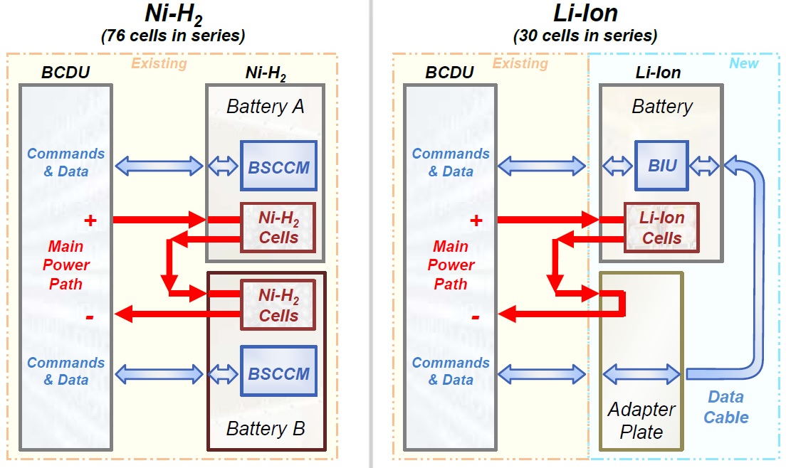
In the existing configuration, two Ni-H batteries are stacked atop one another to create a 76-cell string interfacing with the Battery Charge/Discharge Unit. To make the Li-Ion batteries compatible with the existing Charge/Discharge Units, a Adapter Plate was developed to be installed underneath the Battery to mimic the role of the second battery by passing power from the Li-Ion cells to the Charge/Discharge Unit and route commands and data to the Battery via a data cable to deliver commands to the Battery Interface Unit. The adapter plate is 104 x 91 x 38 centimeters in size and weighs 38.5 Kilograms.
For the battery replacement effort, a total of 24 Li-Ion Batteries and Adapter plates will be flown to ISS on four HTV missions. Six batteries will be installed on each Integrated Equipment Assembly to replace 12 Ni-H Batteries, of which nine will be disposed by HTV and three will remain on the IEA in an unpowered and inactive state. A further three Li-Ion Batteries (without adapter plates) will be flown to ISS as In-Orbit Replacement Units.
The replacement of the aging batteries will be a cooperative effort between the Space Station’s robots and spacewalking crew members. Canadarm2 and the Dextre Robot are equipped with the tools needed to remove the old Ni-H battery ORUs and install the new Li-Ion ORUs in their place, however, the installation of the adapter plates will require at least a pair of EVAs to be performed for each IEA to be outfitted with new batteries.
CDRA Replacement Bed
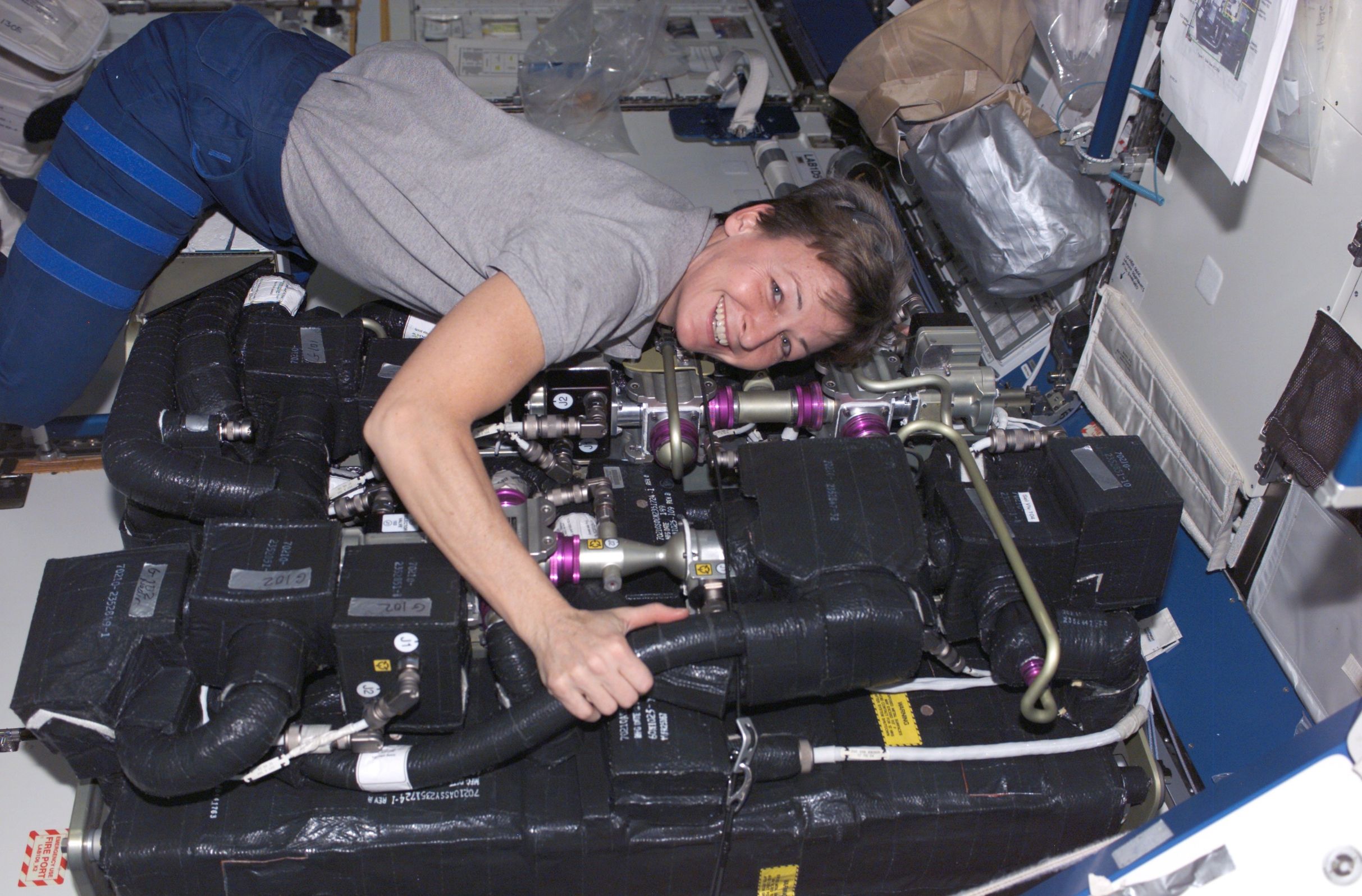
The Carbon Dioxide Removal Assembly, CDRA for short, is a critical part of the Space Station’s Environmental Control and Life Support System ECLSS, responsible for removing carbon dioxide from the ambient atmosphere on the Space Station and, along with the Oxygen Generation Assembly, maintain an atmospheric composition that is safe for the crew. There are two CDRAs onboard the Space Station plus the Russian Vozdukh which is also in use for CO2 removal.
The CDRA maintains the Carbon Dioxide Partial Pressure at under 5.3mmHg for up to nine crew members. Each CDRA unit comprises two beds known as a Desiccant/Adsorbent Bed Orbital Replacement Unit. CO2 rich air enters the CDRA assembly and first passes through a Desiccant Bed of silica gel that removes moisture from the air because the CO2 removal bed is sensitive to water. The adsorbent bed is composed of Zeolite, an aluminum-silicate that acts as a molecular sieve – filtering out carbon dioxide through a highly porous material. A desorbing desiccant bed re-humidifies the air before it is released back into the cabin.

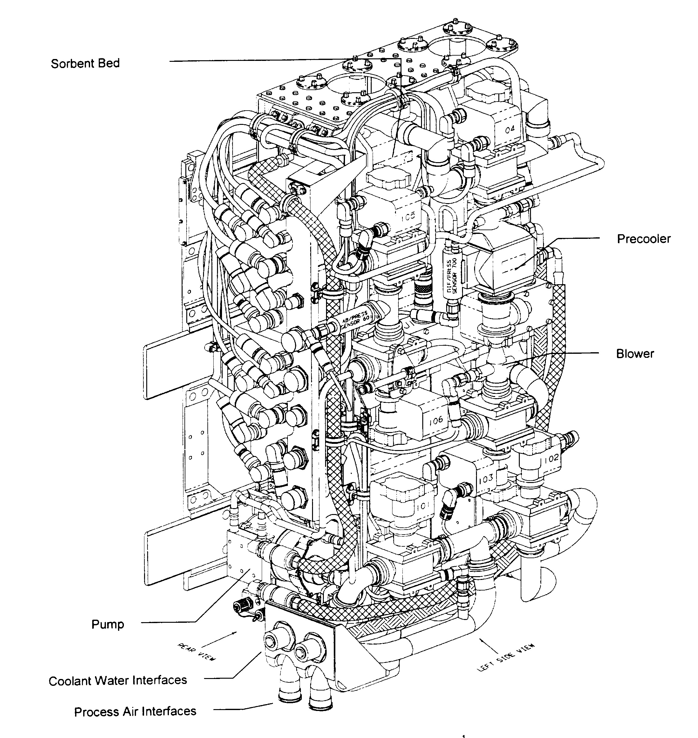
When the Zeolite adsorbent is saturated with Carbon Dioxide, it is exposed to the vacuum of space to remove all the carbon dioxide and regenerate the bed. Two beds are in active use, alternating between adsorption and desorption every 144 minutes.
The CDRAs are relatively complex in design with various pumps, lines and valves to control the flow of air through the different beds. Due to this complexity, the CDRAs have been among the most troublesome components in the Station’s life support system with many crew hours spent maintaining and repairing them.
Teething problems with CDRA included the liberation of fine Zeolite particles from the adsorber which caused trouble in downstream systems including pumps and valves – requiring a quick-fix in the form of filters ahead of a permanent redesign to prevent the escape of fine particles. Regular issues have occurred related to air selector valves and kept teams on the ground and in orbit busy to ensure the CDRAs remain up an running.
Because the CDRAs are prone to issues, a regular supply of replaceable parts is needed and NASA desires to have all parts in stock aboard ISS. HTV-6 is delivering a spare CDRA Bed to be installed later during Expedition 50.
Flight Water
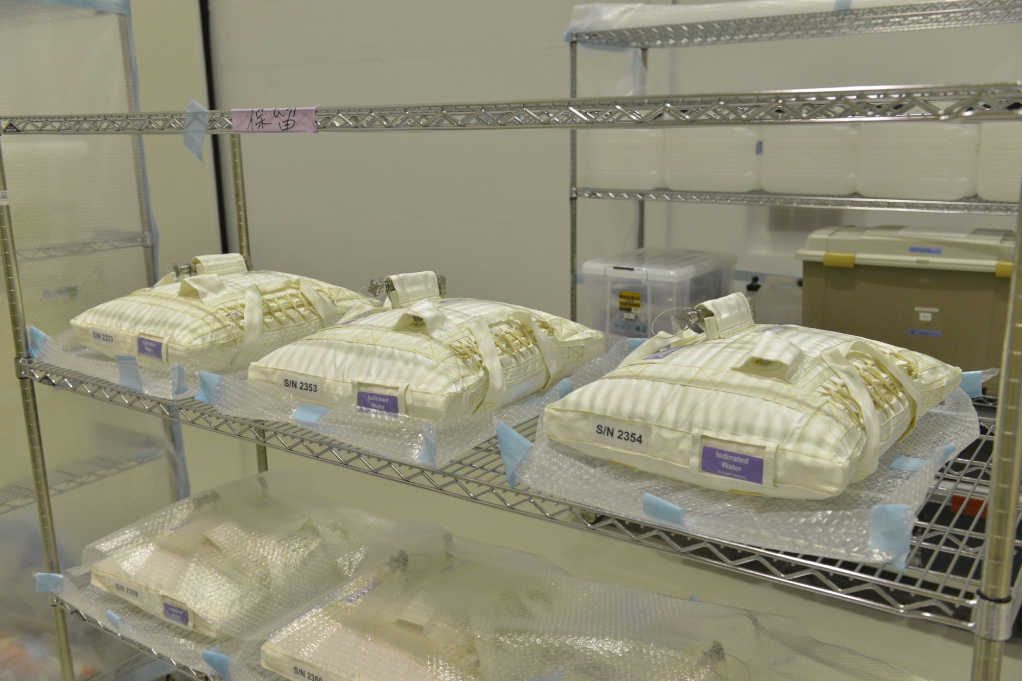
HTV-6 is delivering to ISS 30 Water Container-Iodine Bags (CWC-I) holding a total of 600 liters of water. Flight water for use on the USOS is normally disinfected with iodine and has a low-degree of mineralization while the Russian Flight Water is highly mineralized and disinfected with silver.
Both water types have to meet the technological and hygiene requirements of the International Space Station.
Water delivered on HTV-6 is used for crew consumption and for the Oxygen generation systems aboard the Space Station that use electrolysis to break down water in Hydrogen and Oxygen gas. The Oxygen is released into the Station while the combustible hydrogen is vented overboard.
Two-Phase Flow Experiment
The Two-Phase Flow Experiment is a technical demonstration payload to be operated in the Japanese Kibo Module of the International Space Station to demonstrate a high-performance thermal management system making use of the phase transition of a cooling fluid.
Excess heat is a growing problem on spacecraft due to the increase in spacecraft platform sizes and power consumption. Two-phase cooling systems can be a powerful solution for thermal regulation, making use of the heat transfer in the liquid-gas phase change. However, two-phase flow and heat transfer phenomena are not fully understood in the microgravity environment – requiring testing to improve models for the development of thermal control systems of the future.
The experiment aims to deliver fundamental understandings of the behavior of liquid-vapor transition dynamics and the mechanisms of heat transfer in microgravity conditions. The study is known under the full name “Interfacial Behaviors and Heat Transfer Characteristics in Boiling Two-Phase Flow.”

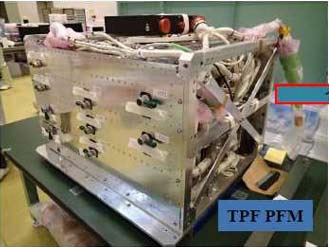
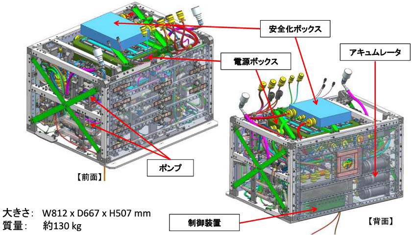
The experiment apparatus is 81 by 67 by 51 centimeters in size and weighs 130 Kilograms and will be installed in the Multi-Purpose Small Payload Rack in the Kibo module, taking advantage of the rack’s power, data and thermal control interfaces. Residing within the apparatus is the test loop through which the working fluid runs, a coolant water loop interfacing with the mid-temperature (16-23°C) cooling loop of the rack, an instrumentation system featuring high-speed cameras, a control system, and a power supply.
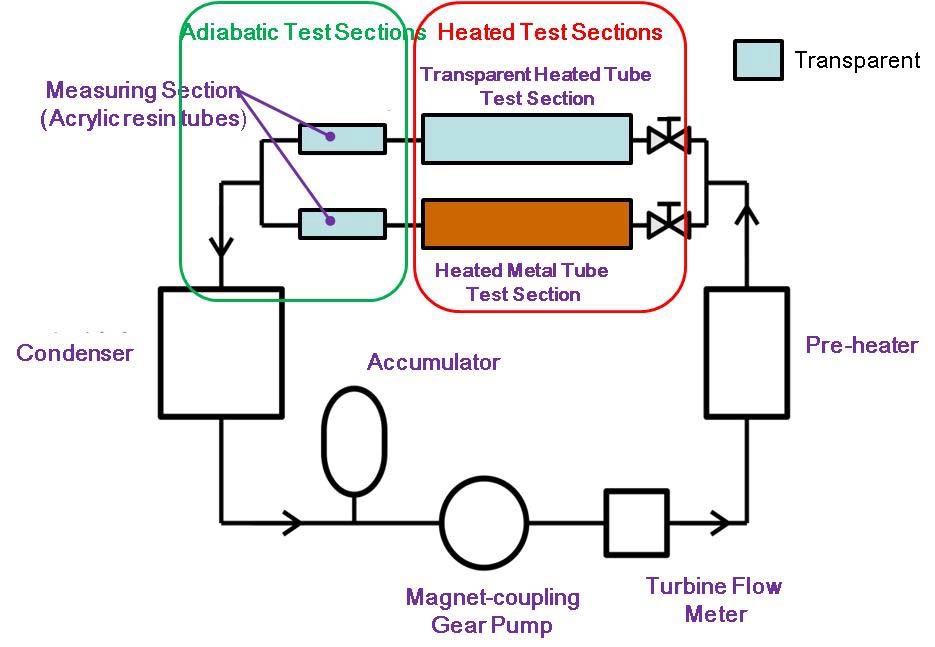
The test fluid chosen for the experiment is FC72, a perfluorocarbon selected for its low latent heat, very low boiling point and low toxicity. The fluid runs through the test loop as a closed system comprised of an accumulator to deal with expansion of the fluid and a magnetic coupling gear pump that moves the fluid through the loop. After passing through a flow meter, the fluid is pre-heated and then enters one of two measuring sections – one with a heated metal tube the other with a transparent tube that make up the heated test section which is followed by the adiabatic test section with two acrylic resin tubes.
The heated transparent tube is observed by three CCD cameras to make visual observations of the gas-liquid interface and boiling heat transfer coefficient flow pattern, observing gas bubbles, and interactions of the two phases. It consists of a pyrex tube with an outer diameter of 6 millimeters and a 4mm inner diameter, coated with 10 nanometers of gold which acts as the heating element of the tube while retaining full optical transparency. The tube is divided in three segments, 8.3 centimeters long and individually heated with their own thermocouples and CCD sensor.

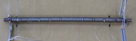
The heated copper tube is 40 centimeters long and outfitted with instrumentation to measure the heat transfer coefficient. The tube has an inner thickness of 4mm and an outer diameter of 12mm; Wound around its circumference is a microheater system and ten thermocouples are embedded in the tube every 33 millimeters at a depth 0.5mm from the inner wall in order to measure temperature changes of the test fluid.
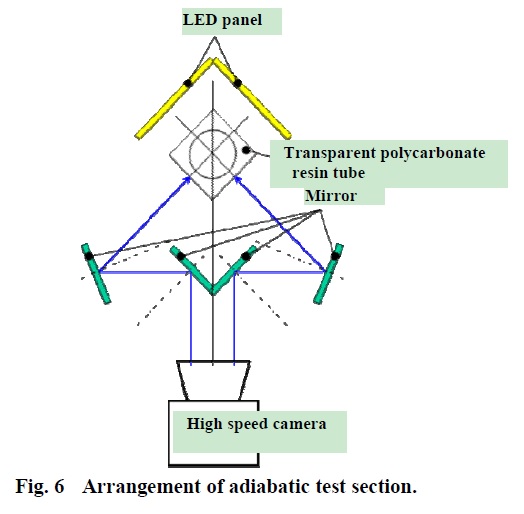
In the adiabatic section, a high speed video camera captures flow pattern transitions, bubble velocity, liquid film structure of annular flow and void fraction. The cameras acquire 1,000 frames per second with an LED panel providing back-illumination of the tube and mirrors allow each camera to observe two look angles at the same time in order to capture the liquid film structure and annular flow.
After passing through the heated sections, the fluid reaches the condenser, a copper tube coupled with a cold plate, where the pressure loss heat transfer coefficient is measured. The condenser comprises eight parallel rods on a conventional cold plate at a length of 33 centimeters. The cold plate is cooled by the 16-23° moderate-temp cooling loop and the heat dissipated from the fluid is calculated by the mass flow of coolant loop water and the measured inlet and outlet temperatures.
The experiment can be varied by setting the liquid flow rate and the heater power which is expected to be 400 Watts, resulting in a fluid mass flow of 0.2kg per hour based on ground tests. The total volume of FC72 in the test loop is 0.6 liters.
Extensive work was completed to ensure the experiment apparatus is safe for operation in the ISS environment and can function leak-free for a mission duration of two years. A long-term study performed with a ground model also verified the testing fluid is stable and shows no denaturation even after many heating cycles. These studies also showed the transparent tubes can retain their optical properties and the pump, flowmeter & pressure sensors can support extended missions.
The experiments performed over the course of the mission have the goal of examining a) heat transfer due to forced convection in annular flow, b) critical heat flux conditions by transition to liquid film, c) heat transfer in different flow regimes, d) nucleate boiling in bubbly flow regimes, e) heat transfer due to nucleate boiling in annular flow & high heat flux, f) condensation heat transfer, f) two-phase flow dynamics – pressure loss, flow regime map & void fractions, and g) the thickness of the liquid film in two-phase flow.
Learning about the mechanisms listed above will clarify the influence of gravity on two-phase flow behavior and heat transfer and better inform designers of future high-capacity thermal regulation systems for application on spacecraft.
PS TEPC

The Position Sensitive Tissue Equivalent Proportional Chamber (PS-TEPC) is a radiation study that measures absorbed doses and path length of space radiation simultaneously and also determines the real time Liner Energy Transfer (LET), and human-tissue equivalent doses for an objective examination of radiation risk to crew members during space flight.
Existing dosimeters for the measurement of radiation-effects on the human body suffer from the fundamental flaw that they do not measure the deposited energy and track length simultaneously due to an inherent difficulty in measuring the path length in real time in space. However, both energy and path length contribute to dose distribution occurring in the human body. As a substitute, current detectors interpolate the path lengths or use averaged estimations, yielding only approximate results.
PS-TEPC has been developed as dosimeter with fine position sensitivity in addition to precise energy measurements using a human-tissue-equivalent material. The study of PS-TEPC in the space environment will reveal whether the instrument is suitable for the real-time monitoring of radiation in the space environment.
An accurate measurement of tissue-equivalent absorbed dose is important because dose management is a crucial aspect for crew members given the radiation environment experienced in orbit is several hundred times greater than that on Earth. Crew members are only partially shielded by the modules of ISS and experience radiation from diverse sources including galactic cosmic rays, solar particle events and trapped particles in Earth’s magnetic field as well as secondary particles such as neutrons that are created when energetic particles are absorbed in the Station’s structure.
Realizing a detector sensitive for all contributing particle types and capable of objectively measuring human-equivalent absorption marks an important step to an accurate real-time monitoring capability for radiation in the human spaceflight environment.
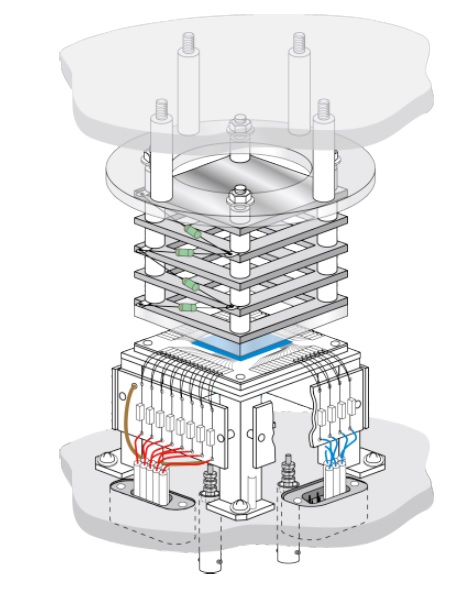
PS-TEPC employs a Time Projection Chamber (TPC) as its detector, consisting of biological tissue-equivalent materials and a Micro-Pixel Chamber acts as the position and energy-sensitive detector acquiring three-dimensional tracks for every particle as well as its energy.
The micro pixel chamber (μ-PIC) electrode array is comprised of a series of pixel-like electrodes on a printed circuit board. The effective volume of the detector hosts A150 tissue-equivalent conductive plastic plates acting as scintillators and an atmospheric tissue-equivalent (TE) gas.
The electrode strips (cathode and anode) are mounted perpendicular from each other at a 400 μm spacing, serving as a 2D position detector while the z-coordinate is obtained from the drift velocity of ionized electrons and drift time using the triggering time of the plastic scintillators and the arrival time of the drift electrons at the electrode.
The PS-TEPC experiment consists of a pair of detector heads and a common control unit. The Low-LET (Linear Energy Transfer) detector covers a range of 0.2 to 600 keV/μm and the high-LET detector 600 to 1,000 keV/μm. The control unit hosts the high-voltage power supply for the μ-PIC electrodes, the analog-to-digital conversion units, a buffer memory and the instrument processor. Data is delivered to the payload rack’s laptop via an Ethernet connection for later downlink to the ground.
ExHAM
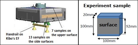
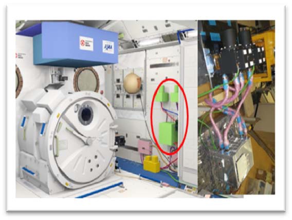
ExHAM is an accommodation system for small experiment payloads for the Japanese Experiment Module Exposed Facility (JEM-EF or JEF) to provide access to space exposure studies to a variety of experiments without the need for spacewalking Astronauts to install exposure payloads. The system is a cuboid mechanism that hosts a grapple fixture for the JEM Remote Manipulator System Small Fine Arm so that it can be transferred to the outside of ISS via the JEM airlock for robotic installation on a JEF hand rail using a clamping mechanism on the underside of the payload.
A total of 20 experiment samples can be facilitated by ExHAM, seven on its upper surface and 13 around the side surfaces of the structure. Each experiment cell measures 10 by 10 by 2 centimeters.
ExHAM modules can be launched with experiments already attached or experiment samples can be launched individually for checkout and installation by the ISS crew followed by the transfer to the outside via the JEM airlock and the installation on the exterior to remain exposed to the space environment (microgravity, radiation, atomic oxygen…) for a specified period of time according to the experiment’s requirements. After return to the inside of ISS, the samples are packed up and returned to the ground for detailed laboratory analysis.
ExHAM simplifies the conduct of materials studies in the space environment and gives a number of institutions from universities to industry partners an opportunity to conduct space exposure experiments.
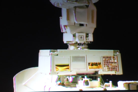
HDTV-EF2
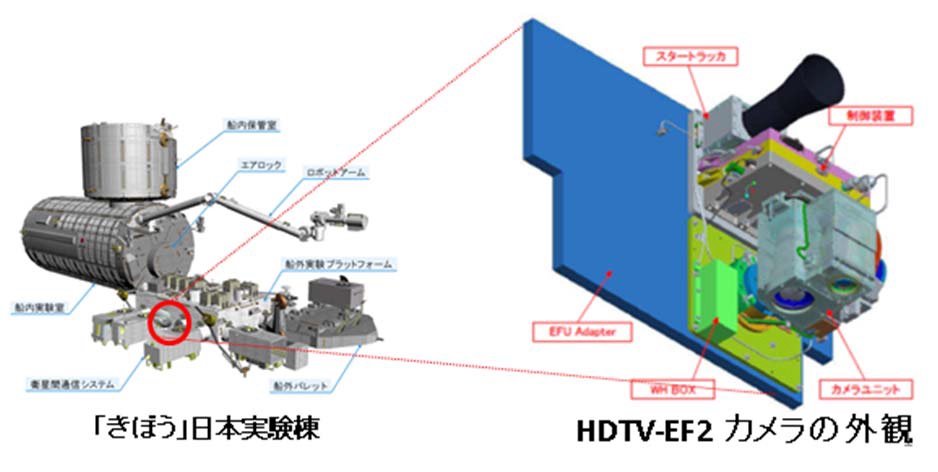
A pair of high-definition TV cameras, 4K and 1080p, are part of the HDTV-EF2 payload to be installed on the Exposed Facility Unit Adapter of the Kibo Module to add to the Station’s high-definition Earth-observation capability. The two cameras are installed on a two-axis gimbal mechanism to be controlled from the ground to target observations of areas of interest.
The HD camera delivers a 1920 x 1080 resolution and downlinks its video in real time through the ISS comm system while the 4K camera collects video at 3840 x 2160 pixels and still imagery at 4240 x 2832 pixels for downlink after acquisition. At the highest 20x optical zoom level, the camera can achieve a ground resolution of 15 meters, suitable for a large number of applications and matching the resolution of small-sized Earth-observation satellites.
Day and nighttime imaging will be employed for fixed point observations, environmental monitoring, disaster response and private use.
SFINKS
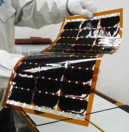
SFINKS (Solar Cell Film Array Sheet for Next Generation on Kounotori Six) is a technical demonstration mission to test the efficiency of thin film solar arrays that could offer significant mass-savings compared to rigid solar panels currently in use by most spacecraft. The thin-film solar array tested on HTV-6 are made by depositing layers of thin-film of photovoltaic material on a flexible plastic creating a thin, lightweight sheet that can take various shapes.
The SFINKS sheet hosts triple-junction solar cells with a high efficiency of 32% with a mass of a 5 x 3-cell array of only 30 grams. SFINKS hosts a total of six five-cell strings on a single sheet installed on the Service Module of the HTV-6 spacecraft.
Over the course of the mission, the voltage and current output from the array will be measured to demonstrate the efficiency of the thin-film cells. The test also looks at the durability of the arrays in the launch and space environment, monitoring possible degradation as a result of ionizing radiation and ultraviolet light from the sun.
J-SSOD and CubeSats
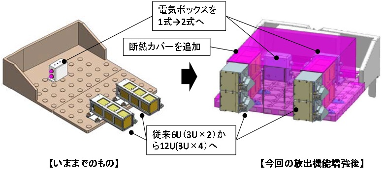
Riding into orbit aboard the HTV-6 spacecraft is an upgraded version of the Japanese Small Satellite Orbital Deployer used to release CubeSats from the International Space Station with help from the Japanese Robotic Arm of the Kibo Module.
The first JSSOD was launched aboard the HTV-3 spacecraft in 2012 and completed the first robotic release of CubeSats from ISS on October 4, 2012 – 55 years after Sputnik was launched as Earth’s first artificial satellite. The first JSSOD offered a total capacity of six CubeSat Units and was followed by other deployers that headed to ISS in the past four years – notably the NanoRacks CubeSat Deployer that has been in use for over 100 satellite deployments, and the SSIKLOPS deployer which provides an orbital launch pad for non-CubeSat missions.

The second JSSOD developed by JAXA, like the first one, employs the Multi-Purpose Experiment Platform as its structural backbone, but hosts four 3U deployers for a total capacity of 12 CubeSat Units. JAXA plans to send an 18U deployer to ISS on the next HTV flight followed by a 48U deployer in 2019.
Deploying CubeSats from ISS has a number of benefits. Launching the vehicles aboard the logistics carrier of ISS visiting vehicle’s reduces the vibration and loads they have to encounter during launch.In addition, they can be packed in protective materials so that the probability of CubeSat damage during launch is reduced significantly. Also, once arriving at the Space Station, the satellites can be checked pre-deployment, making sure any damage is detected before committing them to flight.
Seven CubeSats are being launched as part of the JSSOD-5/6 mission, three 1U satellites (ITF-2, FREEDOM, WASEDA-SAT3) two 2U Satellites (STARS-C & AOBA-VELOX III) and two 3U Satellites (EGG & TuPOD which will deploy two 1.5U Satellites after release).
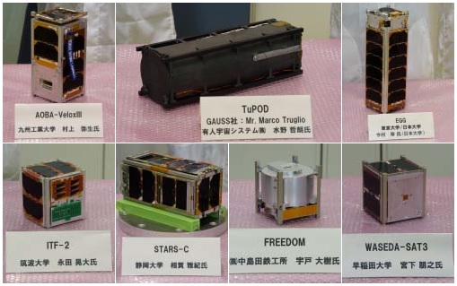
ITF-2
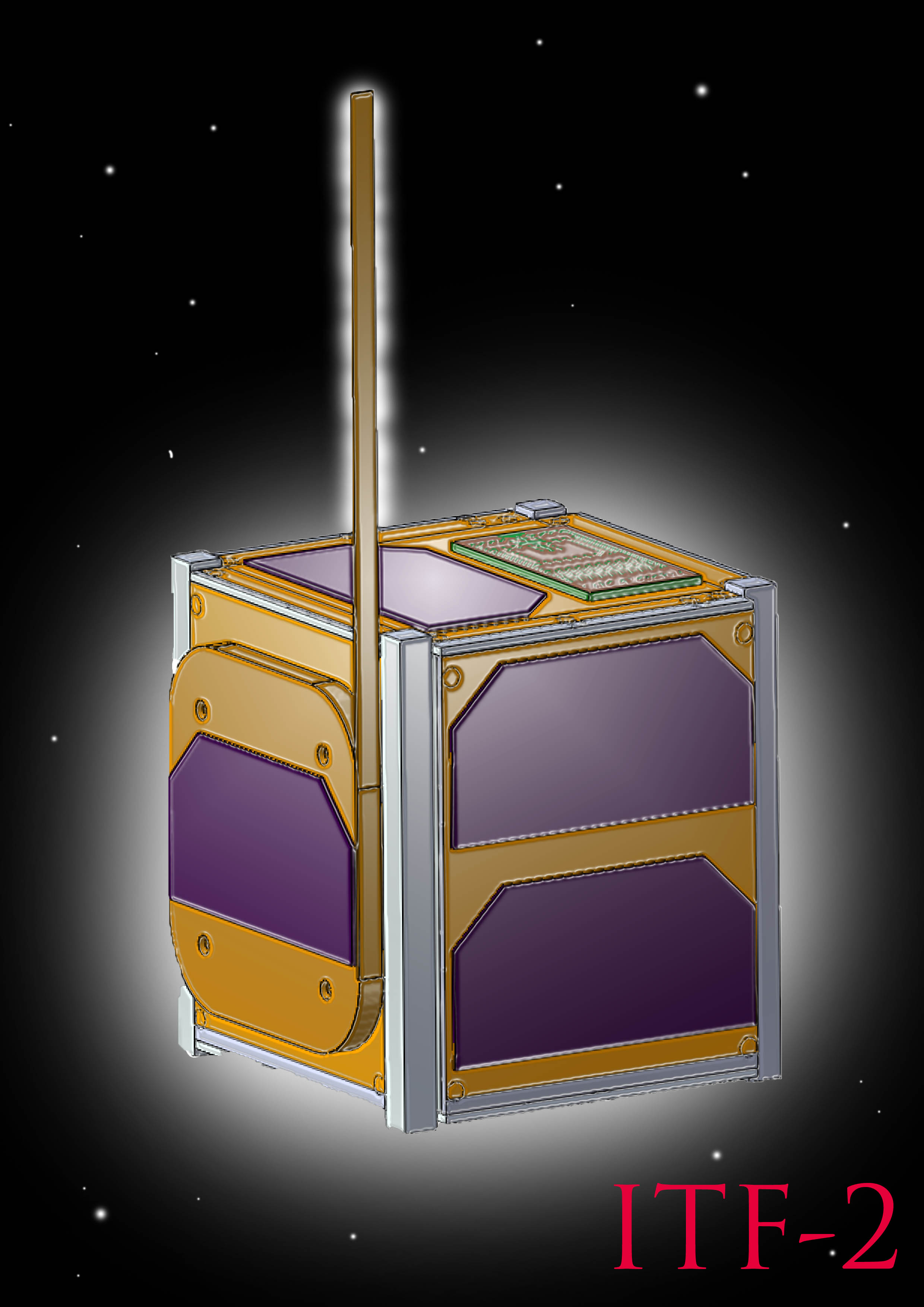
The ITF-2 CubeSat Project is being managed by Tsukuba University. The university slogan is Imagine The Future – explaining the satellite’s name. ITF-2 is also known as YUI meaning bond in Japanese coming from the project concept “Creating the Worldwide Human Community.”
The 1U CubeSat uses the 435MHz UHF Band to send telemetry data (temperatures, voltages & its call sign) and Morse code by audio frequency modulation to engage people around the world to share the messages received from the spacecraft. Expanding from the first ITF mission, the satellite also transmits SSTV image data. ITF-2 demonstrates a 1/20 wavelength micro-engineered antenna suitable to nano satellite missions.
Also, the satellite demonstrates the use of a FRAM (Ferroelectric RAM) micro computer for satellite control, evaluating its tolerance to the radiation environment found in orbit. Another demonstration that is being performed is the use of a ultra small-sized antenna. The printed loop antenna requires no deployment and will demonstrate its reliability over the course of the satellite’s life.
The 1-Kilogram satellite has the typical CubeSat features – body-mounted solar panels, a nickel hydride battery, a rudimentary attitude control system using a permanent magnet and a standard communications system.
FREEDOM
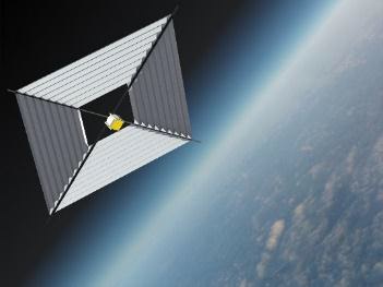
FREEDOM is a 1U CubeSat developed by Nakashimada Engineering Works and Tohoku University to demonstrate a deployable deorbit device for application in future missions for space debris mitigation. The small satellite is comprised of a main structure holding a small bus module facilitating the electrical power system and avionics; and the larger deorbiting device referred to as DOM1500.
The DOM1500 device will form a 1 x 1.5-meter drag sail consisting of a thin-film material supported by four diagonal deployable masts that draw the sail out to its fully deployed configuration when deployment is commanded. The flattened booms are coiled up around a central hub and unwound to pull the thin film from its launch compartment.
The 1.3-Kilogram satellite also hosts a GPS receiver for orbit determination and to track the speed of orbital decay provided by the drag sail. Communications are accomplished with an Iridium modem.
WasedaSat-3
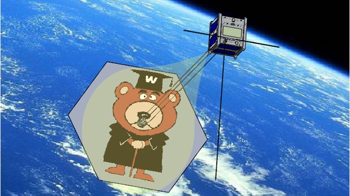
WasedaSat-3 is a 1U CubeSat developed at Waseda University to demonstrate an ultra-light drag chute as a means of deorbiting small satellites after the end of their primary missions to mitigate the growing space debris issues.
The drag chute is made of a thin film hosted in a compartment within the small CubeSat, wound up in a spiral-type folding scheme to unfold into a smooth hexagon using an elastic wire of shape-memory alloy that returns to its pre-formed shape once released from the satellite. When deployed, the drag chute will bring the satellite into a stable aerodynamic attitude since no active attitude control is employed by the spacecraft.
The satellite also hosts a miniature LCD projector that will be used to project images onto the drag chute while a camera captures the projection with Earth in the background. Another purpose of the LCD is assisting the satellite in thermal control, displaying a white color when no increase in temperature is required and switching to black when the satellite needs to be warmed up.
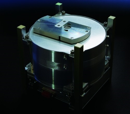
STARS-C

STARS-C is the third mission in the STARS (Space Tethered Autonomous Robotic Satellite) Project of Kagawa University with previous missions in 2009 and 2014. The first two missions consisted of a Mothership and Daughter Satellite connected through a tether with communications through a Bluetooth System.
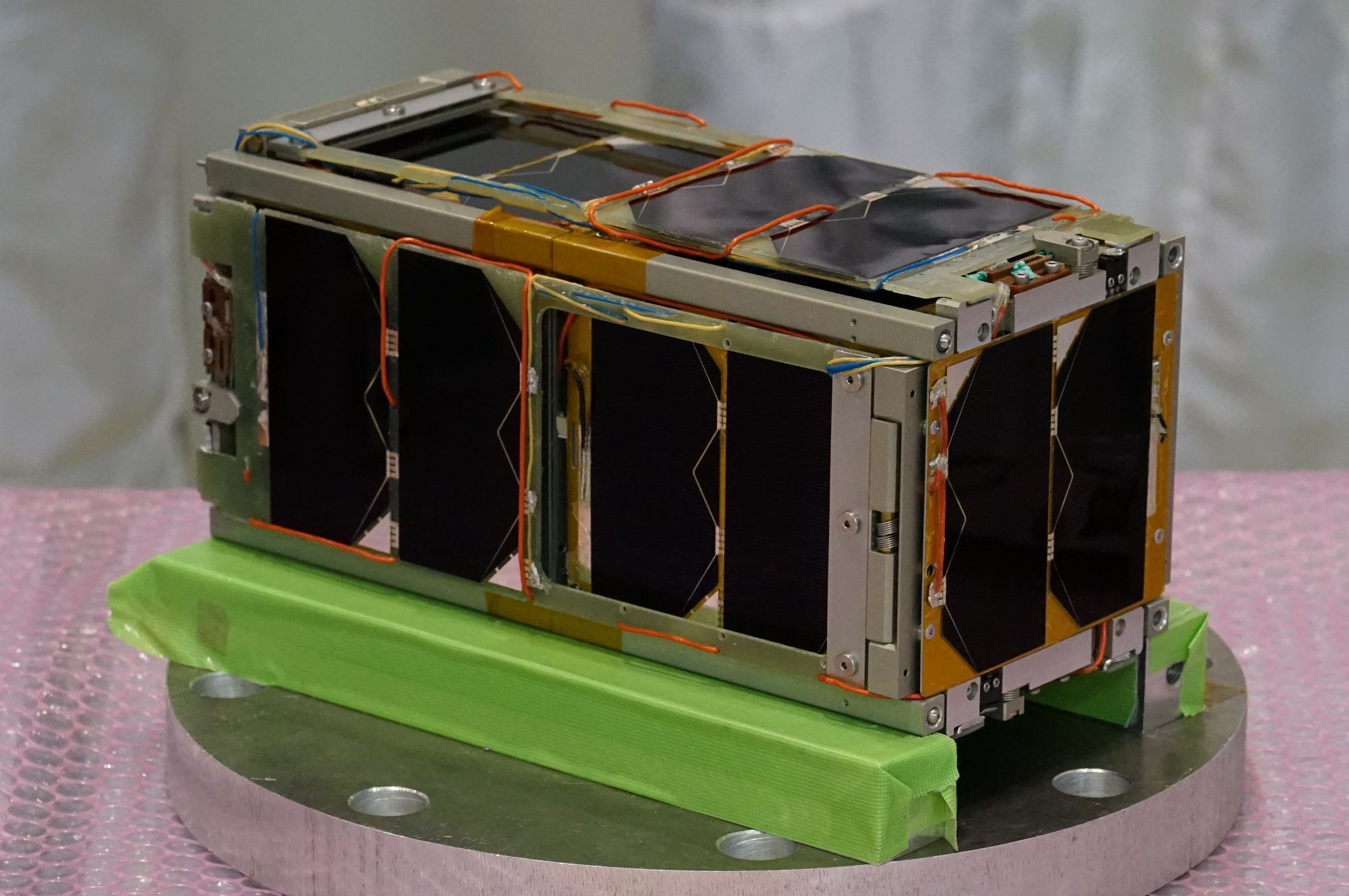
In contrast to the first two STARS missions which used microsatellites, STARS-C complies with the 2U CubeSat form factor with a launch mass of 2.66 Kilograms. It comprises two fully functional 1U CubeSats that will be separated after release from ISS by deploying a 100-meter long Kevlar tether with a diameter of 0.4 millimeters.
The tether deployment sequence is driven by gravitational forces which requires the satellite to hold a defined attitude for the deployment. STARS C will point its daughter satellite to Earth (nadir) and initiate the deployment of the electrodynamic tether. Using springs, the two satellites are pushed apart and the full extension of the tether is accomplished through gravitational forces.
In the extended configuration, the tether collects electrons from the plasma environment in space resulting in a current that can be measured for analysis of the environment and the dynamics of the two tethered spacecraft subjected to the space environment.
AOBA-VELOX-3

AOBA-VELOX-3 is a technology demonstration mission that is the result of a cooperation between Nanyang Technological University, Singapore and the Kyushu Institute of Technology, Japan. The 2U CubeSat will demonstrate three innovative systems for small satellites and future application in a variety of missions.
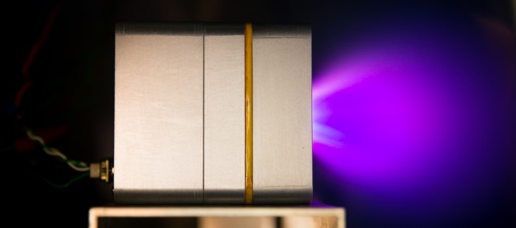
The satellite tests out a pulsed plasma propulsion system that could extend the duration of a small satellite mission by a factor of two by raising its orbit and keeping it out of the more dense layers of Earth’s atmosphere. The Pulsed Plasma Thrusters employ Teflon propellant through which an electrical arc is directed to ablate and sublimate the fuel material. Driven by a 1500-Volt power supply, the electrical arc turns the sublimation gas into a plasma – creating a charged cloud of gas. This plasma closes the circuit between the anode and cathode, permitting electrons to flow which in turn generates an electromagnetic field exerting a Lorentz-force on the plasma. As a result, the plasma particles are accelerate to high speed and propel the satellite.
This type of propulsion system is flexible in that it can be tailored to the power availability on the satellite by varying the time between each discharge (pulse). According to NTU, the propulsion system can lift the AOBA-VELOX satellite 90 meters per hour of operation.
The second innovative system tested on the satellite is a WiFi-based onboard communications architecture that enables the satellite’s subsystems to communicate without the need for a wire harness. This could free up valuable mass and volume on future small satellite missions and is of particular importance for CubeSats which are under strict mass/envelope regulations. AOBA-VELOX also tests a series of off-the-shelf microprocessors to evaluate their durability in the harsh radiation environment in space to assess them for future use on satellite missions.
EGG
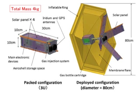
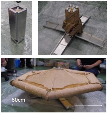
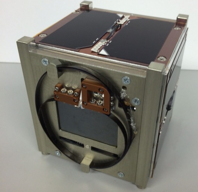
EGG (re-Entry satellite with Gossamer aeroshell and GPS/Iridium) is a 3U CubeSat developed by the University of Tokyo to demonstrate a deployable gossamer aeroshell for re-entry and landing. Flexible aeroshells with low ballistic coefficients are currently being studied for a wide variety of applications including the frequent, reliable and low-cost transport of payloads from orbit to Earth.
Concepts of re-entry vehicles based on flexible aeroshells have been around for decades, however, the technology has not yet found operational use and has so far only been tested on sub-orbital flights.
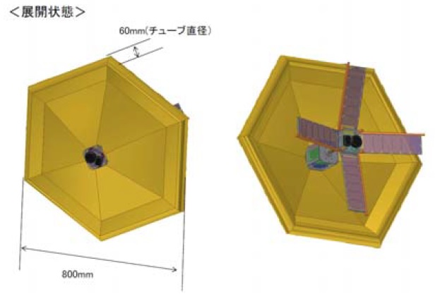
EGG weighs in at 4 Kilograms and hosts a gossamer aeroshell that is to be deployed after the satellite is released from the International Space Station to first speed up the orbital decay process and then shield the satellite body during re-entry. The 80-centimeter diameter gossamer aeroshell is made of a 12.5-micrometer Zylon polymer fiber material that can withstand extreme temperatures and mechanical stress. The hexagonal shape of the aeroshell is achieved by pressurizing a 6-centimeter compression ring on the outer edge of the shell using gas supplied by a pressure cartridge on the satellite.
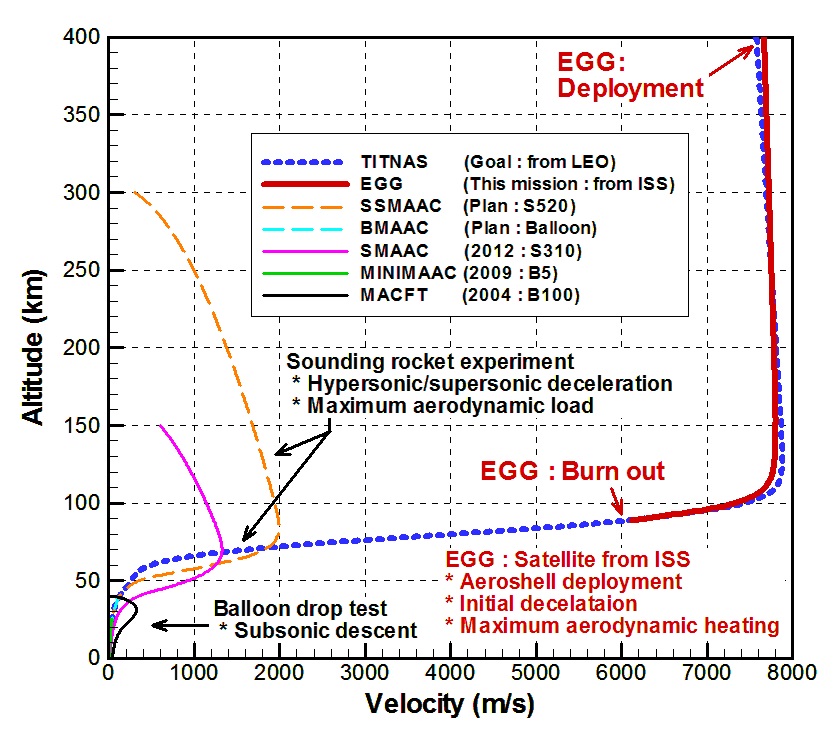
A camera documents the deployment of the aeroshell in the space environment which will accelerate the orbital decay of the satellite, arriving at its entry interface point eight to ten days after the shell is deployed. The satellite body will be shielded by the aeroshell during the exospheric re-entry portion and the initial stages of re-entry to gather data on the dynamics of flexible heat shield technology at orbital speed. Hitting the atmosphere at a speed of 7.8 Kilometers per second, EGG will study the initial deceleration dynamics down to a speed of around 6km/s and an altitude of 80 Kilometers when the satellite will face its fiery demise.
A GPS receiver is used to track the satellite’s position, speed and altitude while an Iridium Short Burst Data modem is used to deliver data collected in real time to the Iridium constellation before the satellite ceases to function.
TuPOD with Tancredo-1 and OSNSAT
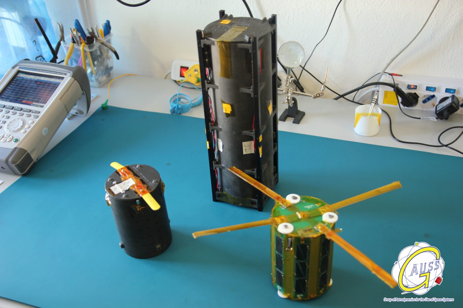
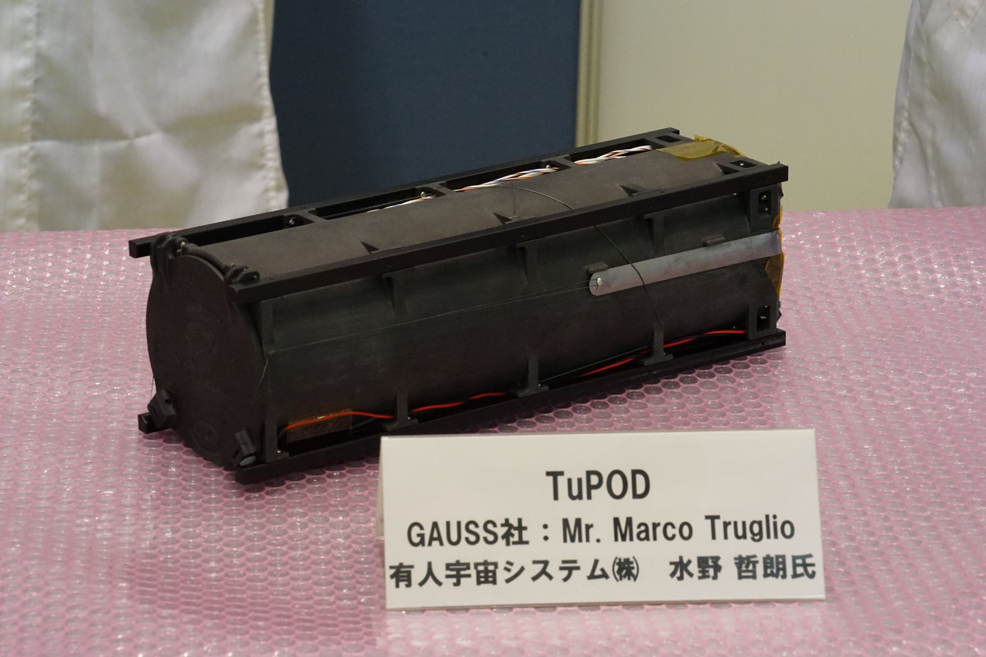
TuPOD is a 3U CubeSat Deployment System developed by Gauss Srl. to deploy a pair of TubeSat picosatellites after released by a standard 3U deployer. The entire structure of TuPOD was 3D printed and the satellite uses a simple battery-powered system that activates at the deployment of the satellite. The two picosatellites will be deployed three days after release from ISS in accordance with NASA regulations.
After releasing its two payloads, TuPOD will continue transmitting a Morse code beacon until exhausting its batteries. When the two satellites have been released, TuPOD is essentially a light-weight hollow cylinder, creating a relatively fast orbital decay to a harmless destructive re-entry.
The Brazilian ‘Tancredo 1’ is the first satellite of the Ubatubasat Project that aims to engage elementary school students in science and technology. The 0.75-Kilogram satellite is based on a commercial kit from Interorbital Systems (IOS), California which was modified with support from INPE engineers. The satellite carries a voice recorder that will transmit a message chosen in a contest among students involved in the project. An amateur radio operating in the VHF/UHF bands is aboard the satellite to allow downlink of telemetry data and commanding to be sent from the ground.
OSNSAT is a TubeSat based on a Interorbital Systems (IOS) satellite kit and operated by Open Space Network, a Californian Space space startup.