
Mohammed VI-A Satellite
Mohammed VI-A, also known under the code name MN35-13 and MN35-A, is a reconnaissance satellite built by Thales Alenia Space and Airbus Defence and Space as the first in a two-satellite system to be operated by the Kingdom of Morocco, primarily for space-based image intelligence collection and as mapping and environmental monitoring platform.
According to official information, the two satellites will be used for mapping and land surveying, regional development, agricultural monitoring, disaster prevention and monitoring, environmental and desertification monitoring as well as border and coastal surveillance.
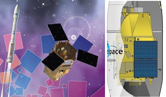
The project was treated with some secrecy and details like the project’s timeline are unclear, though the order for the satellites was placed around December 2013 with Thales’ share given as around €300 million. Arianespace was contracted in January 2017 for the launch of both satellites on Vega rockets in 2017 and 2018.
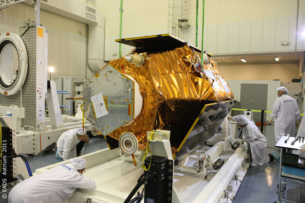
Mohammed VI-A and VI-B were built by a European industry consortium with Thales Alenia Space acting as system prime contractor, supplying the imaging payload including the optical instrument, image transmission system and data processing ground segment while Airbus Defence and Space was the satellite prime contractor in charge of manufacture of the satellite platform and its integration as well as providing the ground segment for mission planning and satellite control.
Thales and Airbus worked in an identical cooperation on the Pleiades-HR two-satellite constellation and are doing the same for two Falcon Eye satellites for the United Arab Emirates launching on Vega rockets in 2018 and 2019. It is understood that all these satellites are based on the AstroSat-1000 platform and share similar capabilities with the missions launching in 2017-19 featuring a number of improvements.

AstroSat-1000 is the largest option in the Airbus family of satellite platforms (also known as AstroBus), covering a broad spectrum of satellite missions from small Earth-observation satellites in the 130-Kilogram range (AstroSat-100/AstroBus-XS), 400kg range (AstroSat-300/AstroBus-S), 750kg range (AstroSat-500/AstroBus-M) and 900-1,200kg range (AstroSat-1000/AstroBus-L). The AstroBus satellites are built to share a number of common avionics components to streamline the production line and reduce overall cost.
The AstroSat-1000 platform for Earth Observation was designed with focus on satellite pointing agility and image location accuracy, driving requirements toward a compact spacecraft design with the imaging payload integrated inside the platform to reduce the length of the satellite while a high image location accuracy is achieved by minimizing the structural interface between bus and payload.
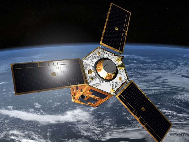
AstroSat-1000 uses a hexagonal structure combining an aluminum truss structure and honeycomb side and internal panels provide mounting surfaces for the various satellite systems. The instrument resides within a central cylinder that doubles as instrument support and baffle; the satellite’s propulsion module, attitude control equipment and avionics boxes are concentrated in the aft section of the satellite structure close to the center of mass to ease satellite control by means of Control Moment Gyros. The propulsion module sits all the way in the back of the spacecraft and the only platform systems on the Earth-facing panel of the vehicle are the communications antennas for housekeeping and telemetry data.
The spacecraft is equipped with three 2.3 by 1.0-meter solar panels that are fixed in position and feature triple-junction Gallium-Arsenide solar cells for maximum performance in order to minimize the physical dimensions of the arrays, also employing Lightweight Panel Structure designs to further reduce the amount of mass away from the satellite’s center of mass.


The Pleiades satellites have been baselined for an orbit-average power of 850 Watts, stored in Li-Ion batteries with a capacity of 150 Amp-hours. Documentation on AstroBus-L shows the typically available payload power around 250 Watts.
Like its predecessors, MN35-A hosts a Monopropellant Propulsion Module featuring a central surface tension tank containing up to 78 liters of Hydrazine (50 l fill level used for Pleiades), pressurized to 25 bar. Four 1-Newton thrusters employ the catalytic decomposition of Hydrazine into gaseous reaction products over a metallic catalyst to generate high-pressure gas. The thrusters are available for assistance in attitude control but primarily used for orbit adjustments at the start of the mission and orbital maintenance over the course of the planned ten-year service life of the satellite.
The 1N thrusters can tolerate supply pressures of 5.5 to 23 bars to generate a thrust of 0.36 to 1.45 Newtons. The corresponding specific impulses are 205 seconds at the lowest supply pressure and 221 seconds at the highest pressure. Each thruster assembly weighs about 0.23 Kilograms and can be operated in steady-state mode and pulse mode for attitude control.
The Attitude Determination and Control System of the AstroSat-1000 platform is designed to provide a powerful combination of high-agility and high pointing accuracy. This is primarily accomplished through the use of Control Moment Gyros for attitude control, providing much higher output torque than conventional reaction wheels which enables rapid re-orientation maneuvers that take only eleven seconds for typical target-to-target slews (200km) and 25 seconds from nadir to the outer edge of an 800km field of regard compared to slews of over a minute if typical reaction wheels were used.

Both, reaction wheels and CMGs, exploit angular momentum to change a satellite’s orientation but with different principles. A CMG consists of a spinning rotor and motorized gimbals that can tilt the rotor’s axis of angular momentum, resulting in a gyroscopic torque acting on the spacecraft, causing it to rotate since the CMGs are firmly installed on the spacecraft structure. CMGs differ from reaction wheels that impart toque by simply changing the speed at which they rotate. Overall, CMGs require less energy and deliver much higher torque than reaction wheels which are simpler in design and, for most spacecraft, are the best solution.
As flown on Pleiades (and likely on MN35-A & Falcon Eye), AstroSat-1000 hosts a Control Moment Gyro system developed by Astrium-Teldix, known as CMG 15-45S. It has four CMGs in a pyramidal configuration for redundancy with a total CMG mechanism mass of 15.7kg, measuring 27 centimeters in diameter and 35cm in height. The CMGs have an angular momentum of 15 Nms, can output a maximum torque of 45 Nm and will operate at an average torque of 19 Nm. This enables the satellite to accelerate to slew rates of 3 degrees per second in just two seconds and traverse its entire field of regard in under half a minute. The CMG assembly is controlled by a single electronics box and each CMG draws a maximum power of 25 Watts.
Attitude determination relies on a gyro-stellar system with three high-accuracy star trackers for precise attitude determination and fiber optic gyrometers for precise measurements of body rates while maneuvering and during initial acquisition.
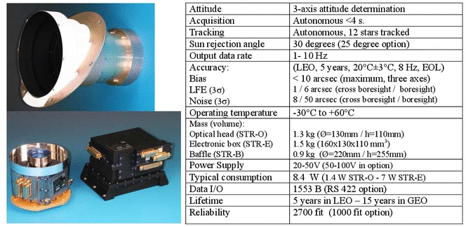
The AstroSat-1000-based Pleiades satellites employed SED36 star trackers developed by Sodern as a follow-on to the SED26 using the same objective, detector, electronics and software but breaking the system down in three separate components to minimize thermal coupling and increase accuracy. The 1.3-Kilogram Optical Head is installed directly on the imaging instrument, featuring a 22-centimeter, thermally decoupled baffle of 0.9 Kilograms while the 1.5kg electronics box is installed within the satellite structure.
The Star Tracker can autonomously acquire the spacecraft’s attitude from a lost in space scenario in under four seconds and tracks 12 stars within its field of view to calculate the three-axis attitude, delivering eight attitude quaternions every second. The pointing accuracy is better than 2 arcsec in FOV error and 10 arcsec for noise, translating to a pointing knowledge on the ground of 10 meters and a pointing accuracy better than 200 meters.
The satellite’s Command and Data Handling System centralizes all computing, monitoring and reconfiguration functions to the On Board Management Unit, OBMU, that hosts an ERC 32 RSIC processor as central computing element. Internal satellite communications are handled via a redundant MIL-STD-1553B data bus with one bus in use for the platform equipment and another for the instrument (the addition of high-speed SpaceWire technology between the Pleiades missions and MN35-A would be a logical step, but cannot be confirmed due to lack of documentation). A dedicated Instrument Management Unit is in charge of instrument thermal control, mechanisms control, detection unit power conversion, and data processing.
The instrument of the MN35-A satellite is of Pleiades HiRI (High-Resolution Imager) heritage, featuring a large-aperture telescope for the collection of multispectral imagery with high geo-location accuracy.
A powerful combination of camera alignment procedures, thermal stability and video processing techniques delivers a very high quality of imagery data for a satellite in the one-metric-ton range.
HiRI was originally developed in a partnership between the French Space Agency CNES and Thales Alenia France with a number of industrial partners including other Thales Alenia branches, e2v as a leader in detector technology, SESO for telescope mirror production, Sodern for the focal plane assembly and Sagem for the instrument’s spectral filters.
The instrument comprises a Korsch-type telescope and state-of-the-art video detection units, operating in a pushbroom imaging concept – using the satellite’s forward motion to sweep out the image swath with off-nadir imaging of targets of interest possible at angles up to 30 degrees.
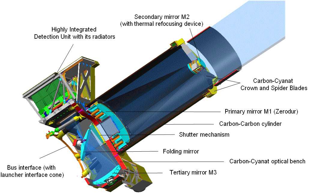
The ~200-Kilogram instrument employs an all-reflective, four-mirror Korsch telescope with Three-Mirror Anastigmat Optics chosen for their excellent performance and wider field of view compared to Ritchey-Chretien arrangements. An additional plane mirror is used to fold the optical path and so make the instrument more compact, in line with the satellite’s overall design striving for agility.
The telescope has a 65-centimeter aperture and is organized around a plane structure that supports the primary, tertiary and plane mirror while the secondary mirror is supported by the central carbon-carbon cylinder – meaning the primary and secondary mirrors reside on the optical axis; the plane mirror directs light onto M3 that resides 90° off-axis and focuses the light onto the focal plane that also resides off-axis. This arrangement allows the compact instrument to achieve a focal length of 12.9 meters.

All mirrors are made of Zerodur, selected because of its excellent thermal properties, and the telescope structure uses Silicon Carbide, characterized by low thermal expansion, low density and high stiffness – ideal characteristics for space-based telescopes. The telescope has a field of view of 20 Kilometers on the ground.
A mechanical shutter assembly resides behind the primary mirror to protect the plane mirror, tertiary mirror and focal plane from solar radiation and external contamination during non-operational phases. The focus mechanism is located on the tertiary mirror.
The Focal Plane Assembly comprises folding and splitting filters to generate two optical paths, one to the Panchromatic Detector and the other to the Multispectral Detector Arrays. For spectral selection, optical bandpass filters are placed very close to the detectors to set the wavelength range for all of the line elements. The MS side has very long multispectral stripe filters using a single piece of substrate with four stripe elements over the detector window for minimization of chromatic aberrations.

All filter elements use space-qualified multi-layer coatings deposited onto glass substrates. Each channel features a pair of filters, one setting broader spectral window and a second optimized to finely define the bandpass according to the respective channel’s requirements. For the MS detector array, absorbing material deposited between the MS filter elements isolates each channel for interband straylight elimination.
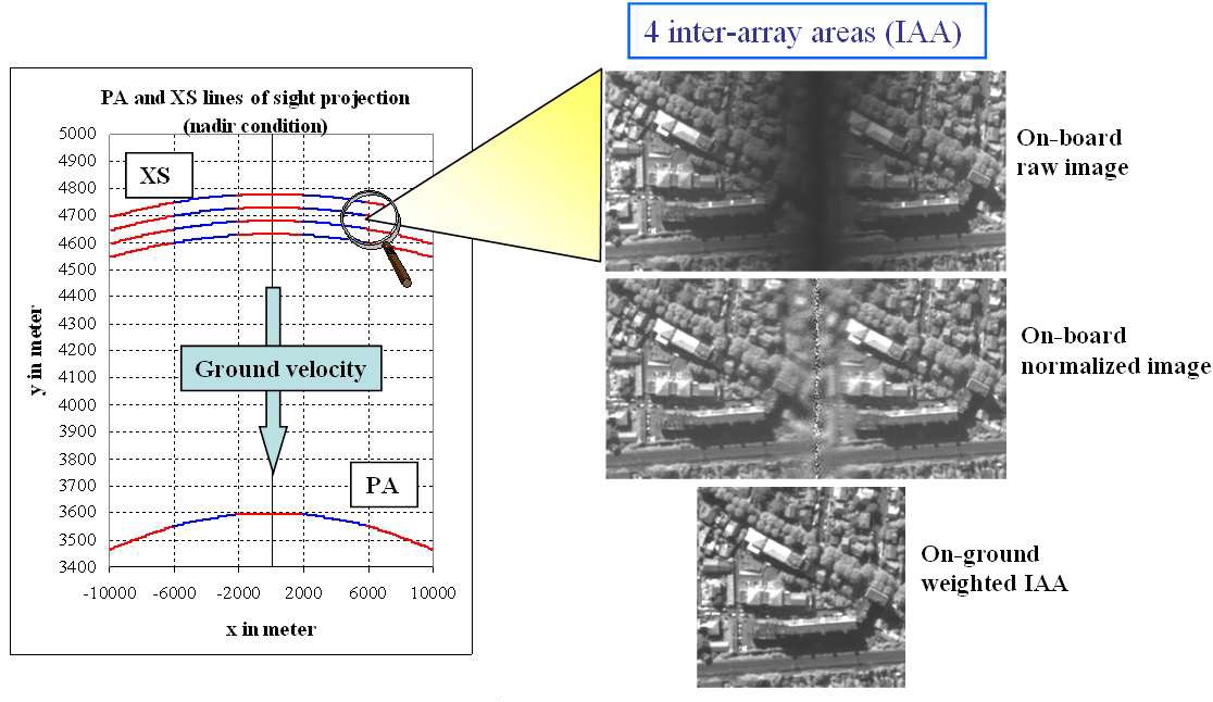
For HiRI, the panchromatic detector hosted five line elements of 6,000 pixels with a pixel pitch of 13µm, sensitive for a wavelength range of 420 to 820 nanometers and achieving a ground resolution of 0.7 meters. The PAN detector used a back-thinned PhotoMOS CCD detector read-out in a Time Delay Integration scheme with five selectable levels. The detector charge transfer was synchronous with the velocity of the scan image swept out by the satellite.

The MS detector array used 7,500 pixels in cross track for each channel (5 x 1500) with 52 µm pixels, permitting a ground resolution of 2.8 meters for the following bands: 450-530nm (blue), 510-590nm (green), 620-700nm (red) and 775-915nm (near infrared). The spacing between each MS line was 936µm.
The TDI detectors were read-out at 290 Mpixel/sec, resulting in a raw data rate of 700 Mbit/s per detector while the MS video chain delivered data at 7Mpixel/sec for optimized signal-to-noise ratio. A novelty on Pleiades was the Highly Integrated Detection Electronics Subsystem (SEDHI) that combined focal plane read-out, 12-bit quantization, video processing, high-speed data link and digital processing capabilities into a single unit directly coupled to the detector Readout Integrated Circuits.
SEDHI is highly modular, allowing it to be configured for a broad range of detector sizes with one or two detectors handled on one circuit board as part of an all-on-one board concept – having the entire pre-amplification to digitization chain on a single building block. The SEDHI boards also provide the low-noise power supplies for their respective detector elements, host the detector clock drivers, synchronization interface and control&command interfaces with the Instrument Control Unit.
The Proximity Video Modules can each process up to ten CCD outputs at 10Mpixel/sec, delivering an output at 1.2 Gbit/s via integrated digital interfaces. Eight processing and four command/control modules are part of the baseline architecture which can be considered an end-to-end “photon in – bit out” system. The entire SEDHI assembly on Pleiades had a mass of 17 Kilograms and required 218 Watts of power, measuring 46 by 24 by 25 centimeters in dimensions.
A separate Payload Data Compression Unit accepts the raw video data and handles compression by up to a factor of 7 before storing the data in a Solid State Recorder. For downlink, three 155Mbit/s channels are conditioned and deciphered for transmission via X-Band, using a gimbaled X-Band antenna. Documentation shows MN35-A uses a single ground station in Rabat, Morocco.
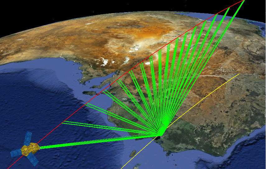
Image acquisition is possible in a variety of modes given the satellite’s high agility. In addition to single-strip imaging, the satellite can be slewed to assemble a 110 by 120-Kilometer mosaic in a single pass. Stereo-imaging with two or three different view angles for a chosen target is possible for the collection of topographic data and multi-spot mode enables the satellite to collect various spot targets located within +/-30 degrees of spacecraft nadir. The overall image geo-location accuracy will be better than 10 meters for 90% of images collected; one meter with ground control points.
