
Göktürk-1A Satellite Overview

Göktürk-1A is a high-resolution Earth Imaging Satellite operated by the Turkish Ministry of Defence, capable of collecting 0.7-meter resolution imagery for use in a variety of military and civilian applications. The satellite was developed and built by Telespazio, Italy as the prime contractor with Thales Alenia Space providing the spacecraft bus with both bus and payload based on flight-proven technology.
Imagery delivered by the satellite will primarily be used for reconnaissance with secondary applications in mapping, urban planning, environmental monitoring, disaster management, coastal zone monitoring and resource management. Göktürk-1A follows the Turkish RASAT imaging satellite launched in 2011 and capable of providing images at a 7.5m resolution in the panchromatic bands; and the Göktürk-2 spacecraft launched in late 2012 with a 2.5-meter resolution. Both RASAT and Göktürk-2 were developed and built as a largely domestic effort while Göktürk-1A is built by leading industry in Europe under contract with the Turkish government.

The contract for Göktürk-1A was signed back in July 2009 between Telespazio and the Turkish Ministry of National Defence and is valued at over €250 million as it includes the development & manufacture of the satellite, the installation of a compatible ground segment, and the construction of a facility for satellite assembly, integration and testing in Turkey. The contract also includes the option of a second spacecraft – to be launched if additional capacity is needed or in case of a launch failure.
The launch of Göktürk-1A was delayed multiple times due to political issues. Israel objected to the launch of the satellite expressing concerns that imagery taken of their territory may fall into the wrong hands.
Israel was responsible for supplying some of the optical components of the satellite and requested that the satellite would have a built-in restriction to prevent images being taken over their territory. Turkey rejected these demands and pressured the satellite manufacturer to prove Göktürk-1A can be operated without geographical restriction.
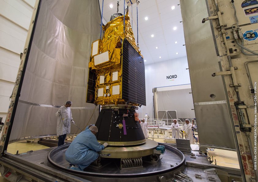
Arianespace’s Vega rocket was selected as the launch vehicle for Göktürk-1A in June 2014 with launch into a 700-Kilometer Sun Synchronous Orbit planned in December 2016.
Göktürk-1A has a launch mass of 1,100 Kilograms and hosts a powerful electro-optical imaging payload coupled to a data system in charge of image compression and downlink via an X-Band Terminal. The satellite collects black-and-white imagery at a ground resolution of 70 centimeters and full color images at 2.5 meters with a re-visit time over the Turkish territory of under two days.
The Göktürk-1A satellite employs the scalable Proteus satellite platform that was developed as a multi-mission satellite bus by CNES and Thales Alenia Space. Proteus uses a modular design comprising a platform module and payload module – allowing payload and bus to be constructed separately before being mated late in the satellite assembly phase.
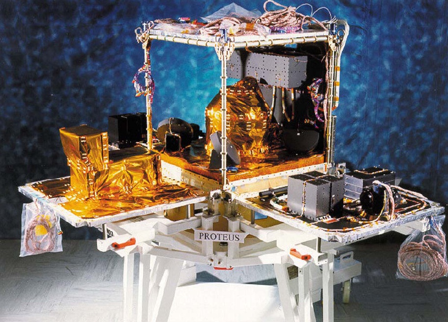
The Proteus satellite bus provided by Thales Alenia is designed for Low Earth Orbit Missions with light-weight payloads between 300 and 1,000 Kilograms. The satellite bus consists of a cubic platform hosting all required subsystems, measuring 1 meter per side.
Proteus first flew on the Jason-1 Ocean Altimetry Satellite launched in 2001 and was used for a total of seven missions prior to Göktürk-1A, though the Göktürk satellites are the heaviest Proteus satellites to date.
The Proteus satellite platform consists of an aluminum chassis to which honeycomb panels are mounted to provide attachment points for the various satellite subsystems. The satellite platform allows a payload assembly to be integrated in a modular fashion using four bolt interfaces. Thermal control relies on passive radiators along with a heater system to maintain components at their critical survival temperatures.
Göktürk-1A features a pair of power-generating solar arrays, each comprised of three panels and rigidly attached to the anti-Earth face of the spacecraft. A Power Conditioning Unit receives power from the solar arrays and generates the satellite’s unregulated power bus at 23 to 37 Volts. Within the Power Conditioning Unit is a Digital Series Regulator that controls the state of charge of a Li-Ion battery; Two identical power interfaces are run from the PCE to the Data Handling Unit where the power distribution function is centralized. A series of fuses and relays ensure bus protection inside the DHU and double isolation circuits upstream from the fuses provide further protection.
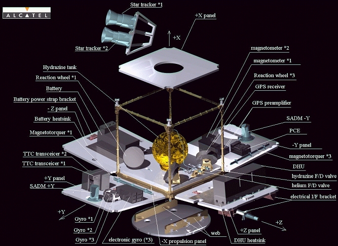
The Attitude Determination and Control System of the satellite is in charge of precisely calculating the satellite’s three axis orientation in space and using a series of actuators to orient the satellite to its nominal attitude, for Göktürk-1A a nadir Earth-pointed orientation. Attitude Determination uses a gyro-stellar concept – using three accurate two-axis gyrometers during the stabilization of the satellite, that is reducing body rates to a point where a pair of Star Trackers can begin to acquire attitude frames.
The Star Trackers, installed on the Payload Module, use optical sensors to collect imagery of the star-filled sky that are then compared to known star constellations by an onboard algorithm for an accurate determination of the satellite’s orientation. Also part of the Attitude Determination System are eight Coarse Sun Sensors and two three-axis magnetometers which come into play during satellite safe modes and operation of the magnetic torquers.
The Göktürk-1A satellite uses reaction wheels as its primary attitude actuation mechanism. The reaction wheel assembly is a rotating inertial mass that is driven by a brushless DC motor spinning the wheel. When accelerating the wheel, the satellite body to which the wheels are directly attached will rotate to the opposite direction as a result of the introduced counter torque.
Because the reaction wheels have to be de-spun at regular intervals, the spacecraft requires a secondary mechanism capable of imparting controlled body rates on the satellite. Three Magnetic Torque Rods with redundant coils are used to create angular momentum by running a current through coils in the presence of Earth’s magnetic field. The torquers are regulated by computers that regulate the current that is passing through the coils in order to control the force generated on each axis. The magnetic torquers are used during momentum dumps and for attitude control in spacecraft safe mode. Actuation of the torquers is commanded based on readings from a three-axis magnetometer.
Overall, the Proteus satellite platform has a pointing accuracy exceeding 0.05 degrees.
The Data Handling Unit builds the brain of the satellite, hosting the onboard computer that runs the flight software to control all platform functions and handle data coming from the satellite payload. It is also responsible for failure detection and recovery, power distribution and command execution across the spacecraft. The main processor within the DHU is a MA 31750 and all interfaces between the DHU and the satellite payload use a 1553 link for commanding. Internal data speeds of up to 10Mbit/s can be supported by the satellite platform.

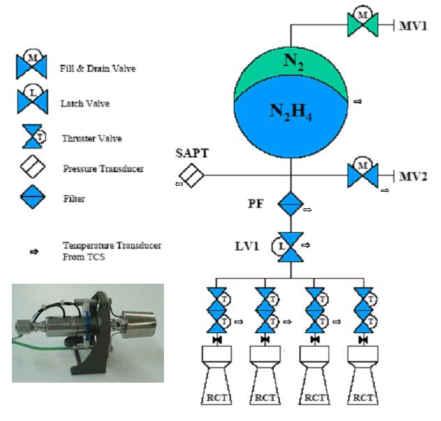
The Proteus platform is baselined for a monopropellant propulsion system built around a central propellant tank that can be sized according to the mission’s requirements. The hydrazine tank feeds a single bank of 1-Newton thrusters, each with its own set of valves. To generate thrust, the system makes use of the catalytic decomposition of Hydrazine over a heated metallic catalyst bed. All four thrusters are installed on the +X face of the satellite to be able to come to use in orbit adjustment maneuvers.
The Communications System of the satellite employs a redundant set of S-Band transceivers interfacing with a pair of feedhorns with cross strapping between the antennas and transceivers as well as the Central Processing Module within the DHU. The S-Band system uses QPSK modulation and reaches a downlink data rate of 838 kbit/s and 4kbit/s for uplink.
The payload carried by the Göktürk-1A satellite is comprised of a High Resolution Imager coupled with a data processing and X-Band downlink system – both nearly identical to the units used on the French Pleiades-1 Earth Observation Satellites launched in 2011 and 2012.
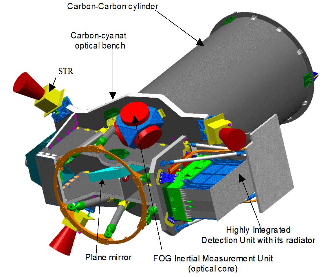
The High Resolution Imager (HRI) delivers high-resolution panchromatic and multispectral imagery with high geo-location accuracy – employing a pushbroom imaging concept – recording the image strip swept out by the satellite’s orbital motion. The optical telescope makes use of a Korsch-type arrangement with a Three Mirror Anastigmatic (TMA) optical system plus a fourth plane mirror designed to make the instrument more compact. TMA optics offer a larger field of view than the conventional Cassegrain or Ritchey-Chrétien systems that also find application in spaceflight.
HRI has an aperture diameter of 65 centimeters and hosts a central plane structure that holds the primary, tertiary and plane mirrors while the secondary mirror is held in place by a cylindrical structure for a total instrument focal length of 12.9 meters. The optical assembly comprise a pair of on-axis collector mirrors (M1 & M2) and off-axis mirrors (M3, MR) that feed the focal plane assembly. The telescope’s mirrors and many of the structural components are made of silicon carbide, chosen for its robustness and its excellent thermal stability.

The Focal Plane of the HRI instrument is comprised of two symmetrical detector assemblies, one for the Panchromatic Band and a Multispectral detector – fed by a beam splitter assembly comprised of several splitting and folding mirrors. Placed in front of each line detector in the multispectral focal plane is a two-layer spectral filter to select the wavelengths imaged by each detector. Each filter makes use of a high-pass filter and low-pass filter to precisely select the bandpass with the filters using an absorbing material deposited onto a glass substrate.
The HRI instrument hosts an external aperture cover for foreign object protection and an internal shutter protects the tertiary mirror and detector assembly from solar illumination during non-operational mission phases. HRI’s structural system also facilitates the spacecraft’s star tracker optical heads and gyroscope assemblies to improve the instrument pointing performance and image geo-location accuracy.
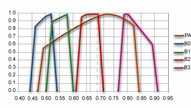
The PAN detector array hosts five 6,000-pixel lines for 30,000 pixels in the cross-track direction while the Multispectral assembly makes use of five 1,500-pixel strips to cover five wavelength bands. PAN employs small 13-micrometer pixels while the MS array hosts pixels with a 52 µm pitch to cover the same area as the PAN detector. The PAN channel covers a wavelength range of 480 to 820 nanometers; the five multispectral bands cover blue (450-530 nm), green (510-590) and red (620-700) for the assembly of full-color imagery plus a near-infrared band at 775 to 915 nanometers.
The instrument covers a ground swath of 20 Kilometers at nadir and the satellite can support off-nadir imaging at angles of 30 degrees to either side, generating a repeat cycle of around two days for the Turkish territory. Image location accuracy is expected to be 1 meter with ground control points and ten meters without.
HRI comes with an integrated set of detector electronics to process the video data from the detector, compress and encrypt it, and downlink it to the ground via a high-speed X-Band terminal.
A series of Proximity Video Processing Modules read out the CCD outputs and high-speed data links relay the digitized signals to the Payload Data Compression Unit that operates with a standard compression factor of 4.8 before storing the data in a Solid State Recorder from where the data is read-out at a rate of 465Mbit/s on three 155Mbit/s channels for downlink via X-Band only after going through encryption completed by a dedicated electronics unit. The X-Band terminal hosts Solid State Power Amplifiers feeding the downlink to a 64° omni-antenna installed on a 2-axis gimbal to track the ground station and maximize downlink efficiency.