
TESS Instrument Overview
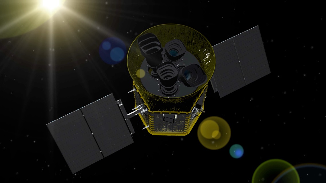
NASA’s Transiting Exoplanet Survey Satellite (TESS) hosts a single instrument comprising four identical Wide Field Cameras to be able to observe a sizeable sector of the sky and, over the course of a two-year primary mission, obtain an all-sky survey of transiting exoplanets in orbit around bright stars close to Earth. The payload consists of the four optical cameras, their associated hoods, structural mounts, sun shield and the Data Handling Unit, all residing in a 1.2 by 0.65-meter instrument module attached to the TESS satellite platform.
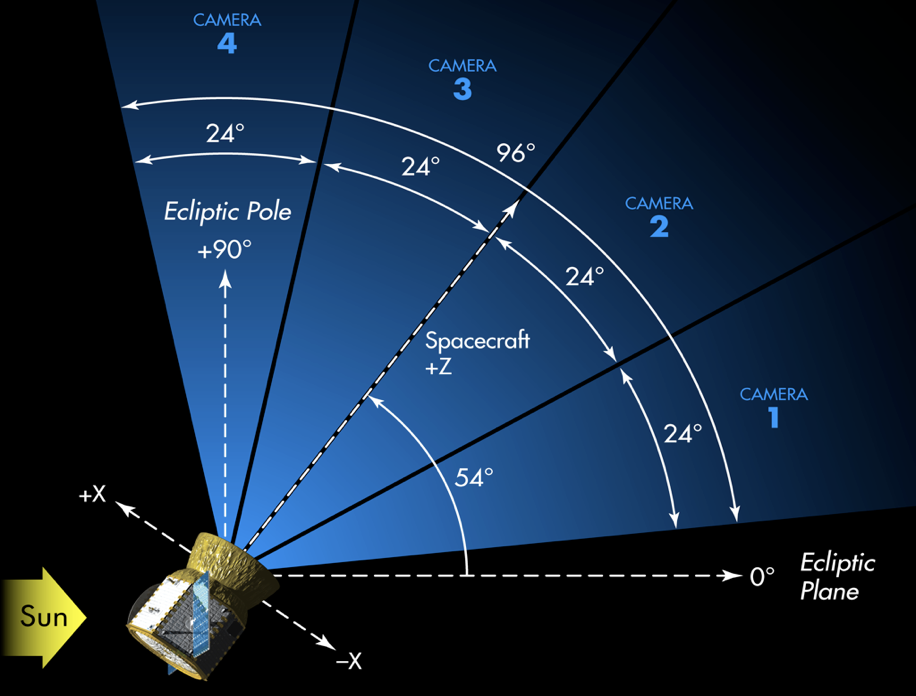
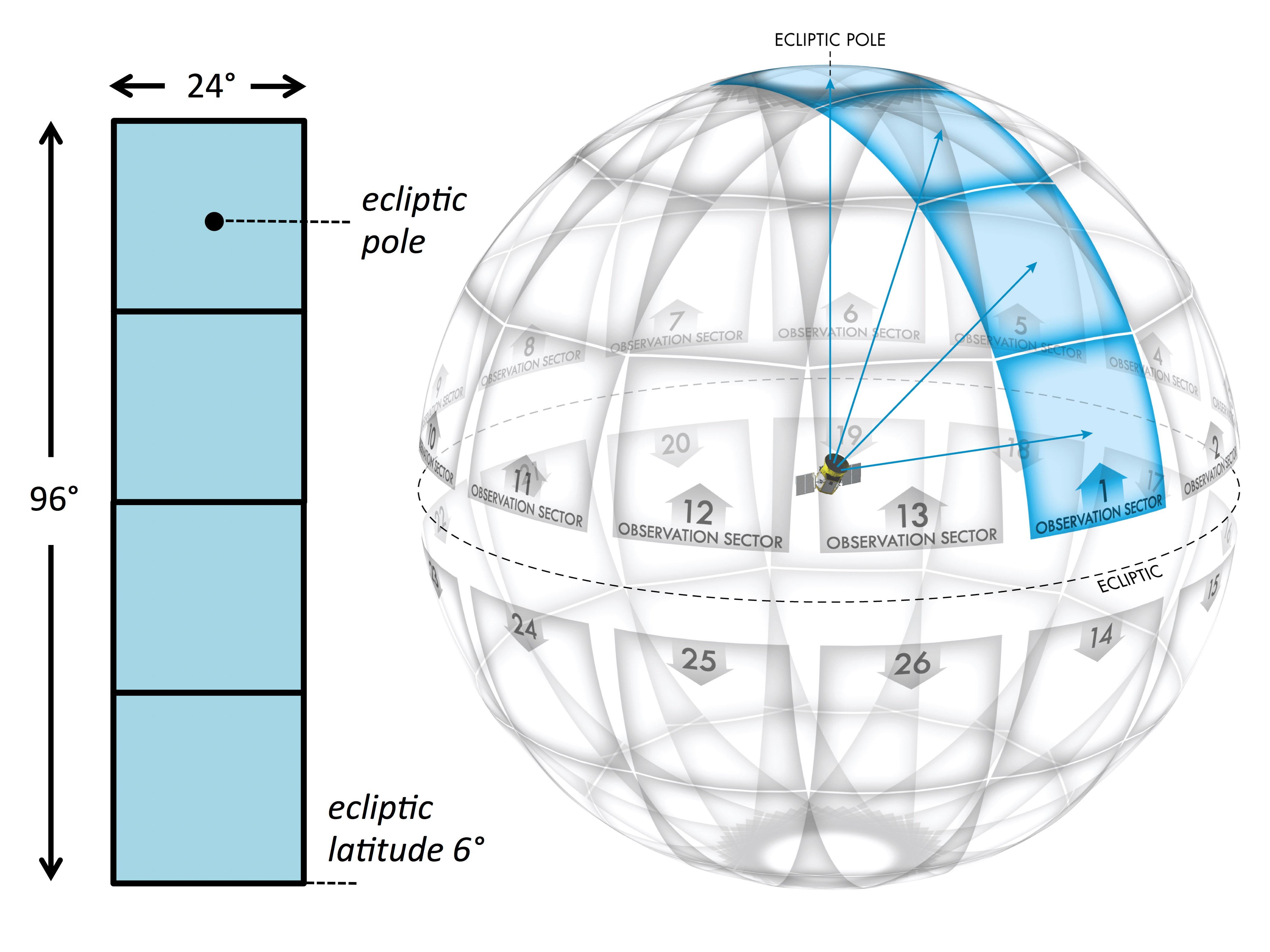
Each of the four refractive camera assemblies has a field of view of 24 x 24 degrees and they are arranged such that a 24 x 96-degree sector of the sky can be covered by the spacecraft as part of a staring observation concept to register exoplanet transits around a set of at around 15,000 target stars per sector.
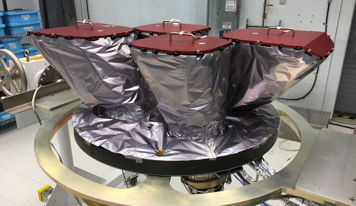
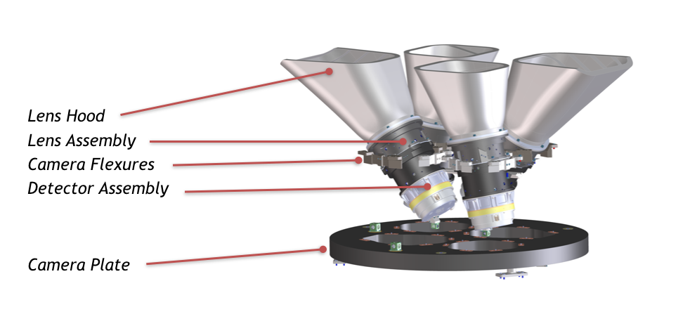
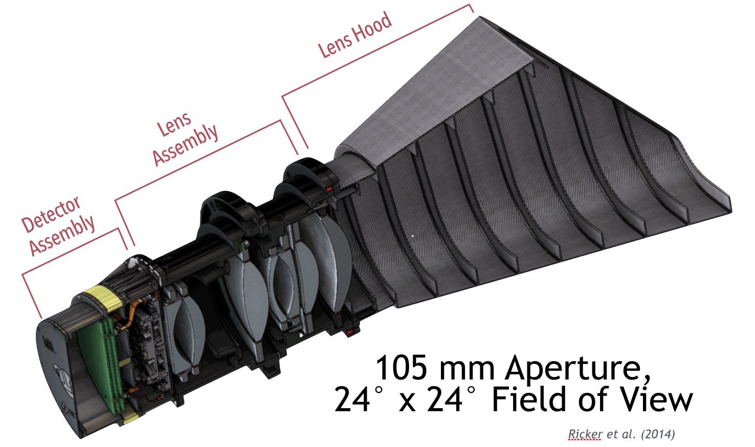
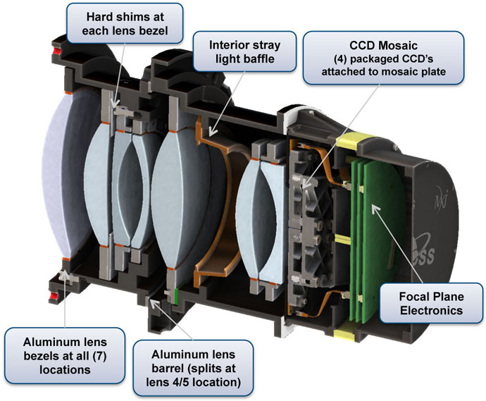
Each of the four camera units consists of a seven-lens optical assembly with a 105- millimeter effective pupil diameter and a focal length of 146 millimeters, a 600-1,000-nanometer bandpass and a 16.8-Megapixel low-noise, low-power CCD detector assembly. All four cameras are installed on a single plate to maintain their FOV arrangement and two of the cameras have 12° lens hoods while the others have a 36° hood tasked with rejecting scattered light and acting as a thermal radiator for the camera assembly.
The f/1.4 lens assembly comprises seven elements with five spherical and two aspheric lenses, facilitated in two aluminum lens barrels that are fastened and pinned together. All optical elements have anti-reflection coatings and one element has a long-pass filter coating that sets the lower cutoff of the instrument bandpass at 600 nm; the upper limit at 1000nm is set by the quantum-efficiency curve of the CCDs.
Each lens assembly focuses a 24 x 24° unvignetted image onto the focal plane that facilitates four back-illuminated MIT/LL CCID-80 devices, consisting of 2048 x 2048 pixels and a 2048 x 2048 frame store region. The square pixels have a side length of 15 µm and there is a 2 mm gap between the four CCDs, creating an effective image array of 4096 x 4096 pixels over a 62 x 62 mm effective area. The frame-store region employed by the CCID-80s allows for a shutterless readout in 4 milliseconds.
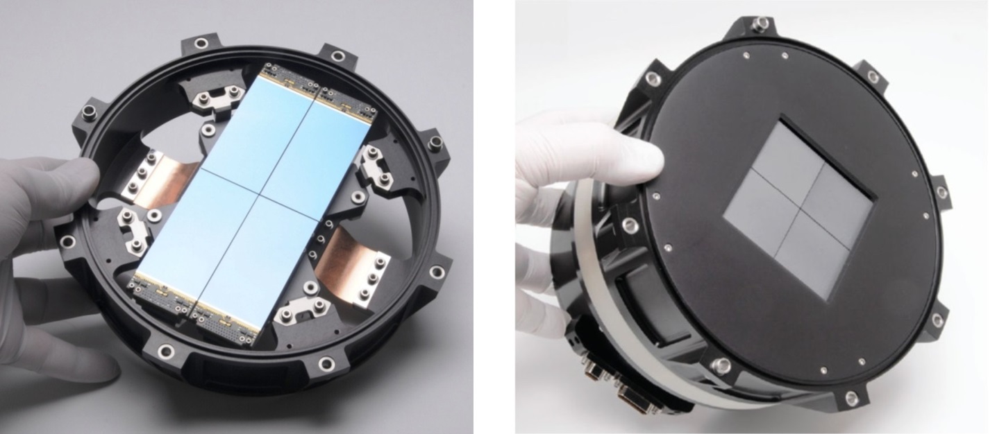
On each CCD, there are four regions of 512 columns, each with its own MOSFET-based output register operating at 625 kHz. Pre-flight testing showed the full well capacity of the employed CCDs at over 190,000 electrons.
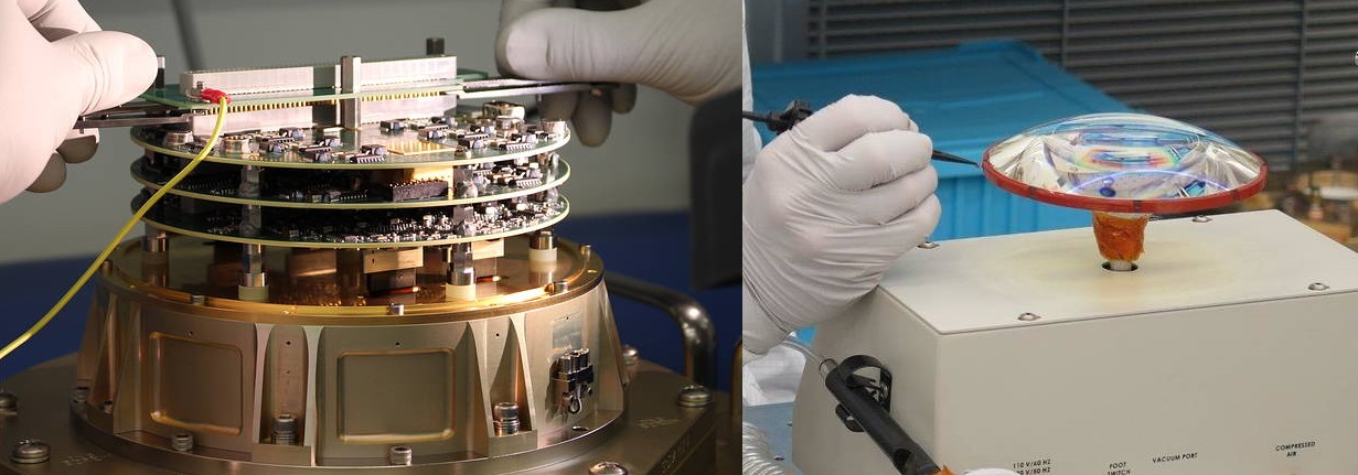
The detector electronics are facilitated on two printed circuit boards 12cm in diameter and installed directly beneath the focal plane to process the analog pixel read outs into digitized video data relayed to the Data Handling Unit via a high-speed LVDS link (Low Voltage Differential Signaling).
The detectors employed by TESS have a thickness of 100µm that offer a 20% improvement in quantum efficiency at the 1,000 nm measurement wavelength compared to standard 45µm CCDs. A high quantum efficiency in the red and near-infrared wavelength is particularly important for TESS given the desire to observe M-type dwarfs which are small, cooling stars with emissions in the red spectral bands. Because of their smaller size, exoplanet transits are particularly easy to detect around M-dwarfs due to the large decrease of relative brightness during a transit.
Compared to Kepler, the TESS bandpass is wider and shifted toward higher wavelengths due to the mission’s differing target priorities: Kepler was focused on sun-like stars while TESS is optimized for cool stars while also maintaining a fair capability for observing M-type stars.
The CCDs are maintained at a temperature of -75°C to reduce dark currents to a negligible level and the unique orbit employed by TESS allows the focal plane temperature to remain at a low drift of 0.1K/hour for 90% of the orbit and 2K/hour over the entire orbit.

Transit Photometry Principle
Transit photometry is the most commonly used method for detecting exoplanets and measuring their radii. If a planet crosses (transits) in front of its host star (as seen from the observer) it will cause the star’s visual brightness to drop. Depending on the relative sizes of the star and planet, this drop can be as large as 2% in observed brightness, but in most cases is only a few hundreds or a few thousands of a percent – requiring highly accurate instruments to make a conclusive detection.
Transit photometry is the favored method for exoplanet candidate detection as hundreds or thousands of stars can be observed simultaneously. However, the method has a number of drawbacks – the probability of a line-of-sight transit is rather low and it can not be guaranteed that any particular star is not a host to planets just because no transits are observed, even after an extended observation period.
Another factor is a large number of false detections which requires exoplanet candidates identified through photometric measurements to be verified through another method like measuring the star’s radial velocity which will reveal whether planets are orbiting around it and influencing the star’s relative velocity to Earth by their gravitational fields.
Nevertheless, transit photometry and radial velocity measurements have proven to be a powerful combination as the former provides the planet’s radius by means of the fraction of light blocked by the planet and the latter provides the planet’s mass that arises from its gravitational influence on the host star. This in turn allows a planet’s density to be calculated from which some conclusions on its physical characteristics can be gleaned. Spectroscopic transit measurements can also reveal details on the composition of the exoplanet’s atmosphere and secondary eclipses (when the planet disappears behind its star) can reveal its temperature.

Scanning Strategy
To accomplish a complete all-sky survey over a mission duration of two years with the constraints imposed by the instrument’s capabilities, TESS employs a specially-developed observation strategy – focusing on the Northern Hemisphere for the first year of the mission and covering the Southern Hemisphere in the second year. Each hemisphere is divided into 13 partially overlapping sectors of 24 x 96 °, extending from an ecliptic latitude of 6 degrees to the ecliptic pole – naturally there will be overlapping coverage closer to the ecliptic pole and gaps close to the ecliptic plane (up to 3°) plus the +/-6° cut-out zone around the ecliptic plane.
Within each sector, TESS will observe 15,000 of the brightest stars as target stars, creating what is known as a postage stamp for each star – essentially cutting out a window of 10 x 10 pixels centering the target star. These postage stamps will be collected every two minutes while Full Frame Images will be summed over 30 minutes. With an observation arc of 27 days per sector, this will yield over 600 Full-Frame Images and some 10,000 postage stamps for every of the 15,000 target stars.
TESS will keep staring at each sector for two orbits before slewing eastward to cover the next sector. Per the craft’s observing strategy, the cameras will point nearly anti-solar to fully eliminate stray light.
All in all, 90% of the sky will be observed by TESS and the coverage has been shifted to create the maximum overlap of 351 days in the Continuous Viewing Zone of the James Webb Space Telescope at the ecliptic poles to maximize the odds of exoplanet detection. Overall, TESS will cover around 30,000 square degrees observed for at least 27 days, 2,800 square degrees are observed for more than 80 days and 900 square degrees surrounding the ecliptic pole are observed for nearly one year:

Science Data Flow
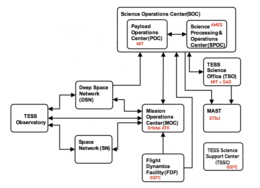
TESS will deliver the data it collects over the course of a 13-day observation arc as part of a single Ka-Band downlink, performed when passing perigee and slewing away from its observation sector. This data dump includes nearly 10,000 postage stamps for every target star plus over 600 full frame images of the entire observation sector.
Downloaded through the Deep Space Network, the data will be relayed to the Payload Operations Center (POC), located at MIT. POC delivers uncalibrated, re-quantized pixel data, target lists, spacecraft configuration, engineering data and focal plane characterization models to the Science Processing Operations Center (SPOC) at NASA Ames where a two-step calibration process is performed, first by the orbit and then by the observation sector. Once a full sector is calibrated for two science orbits, the data will be run through the planet search software to automatically flag threshold crossing events (TCEs).
Calibrated target star pixels, Full Frame Images, light curves and TCEs are then transmitted to the TESS Science Office that includes members of MIT and the Smithsonian Astrophysical Observatory for detailed analysis of the TCEs to reject false detections and identify TESS Objects of Interest. A list of these objects is then delivered to the Mikulski Archive for Space Telescopes along with auxiliary data that documents the TCE analysis process.
