
SpinSat
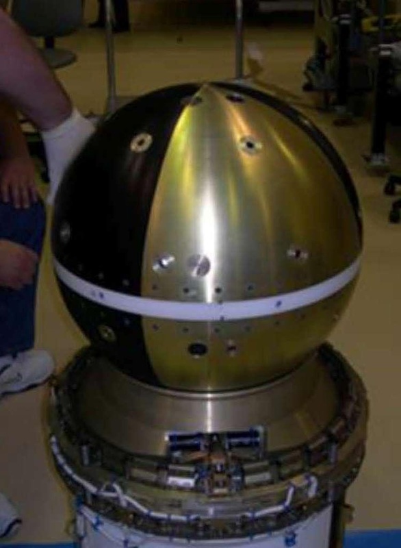
SpinSat is a project of the Naval Research Laboratory and Digital Solid State Propulsion LLC. The 57-Kilograms SpinSat spacecraft is spherical in shape with a diameter of 55.8 centimeters. Its mission is to demonstrate ESP (Electrically -controlled Solid Propellant) technology in space and to provide a calibrated drag experiment for the measurement of the total neutral atmospheric density. The project builds on the ANDE (Atmospheric Neutral Density Experiment) missions that flew in 2006 and 2009.
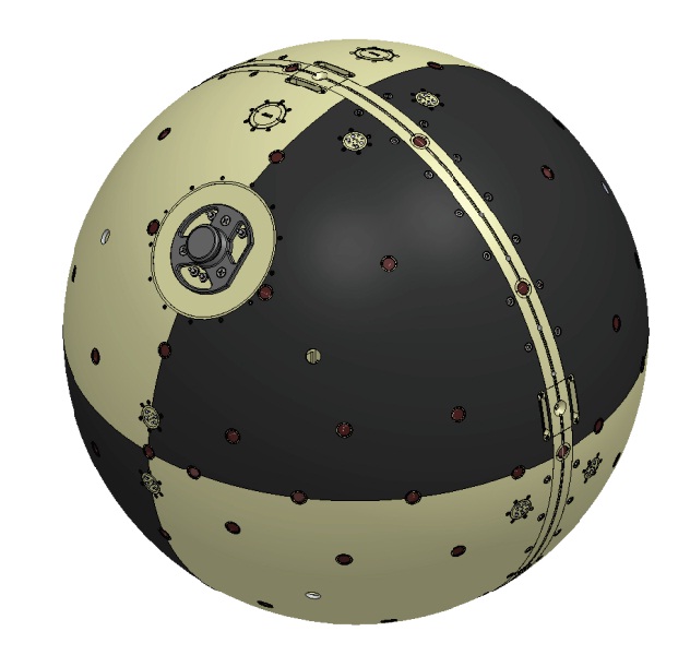
The spacecraft consists of an aluminum shell that facilitates the interface with the SSIKLOPS deployer, a number of laser retroreflectors and the ESP thrusters which are arranged to deliver to basic types of maneuvers.
Internally, the satellite consists of a stack of modules starting with an equator deck that hosts the satellite antennas and a number of thrusters. Located below the equator is a battery package, the thruster control unit and an inertial measurement package. Located above the equator is another battery package, a thruster controller and the main electronics of the spacecraft.
The ESP thrusters are physically arranged on the exterior of the satellite to provide two basic types of maneuvers – spin-up (de-spin) in tangential direction and a thrust maneuver normal to the spacecraft axis. The spin-up and de-spin maneuvers are realized with two active thrusters co-aligned 180 degrees apart. Normal thrust maneuvers are accomplished using thrusters installed on the poles of the spacecraft. Four pairs of thrusters are installed at +/-15 degrees for the spin maneuvers and two pairs of thrusters are mounted in longitudinal bands at +/-82 degrees, normal to the sphere surface.
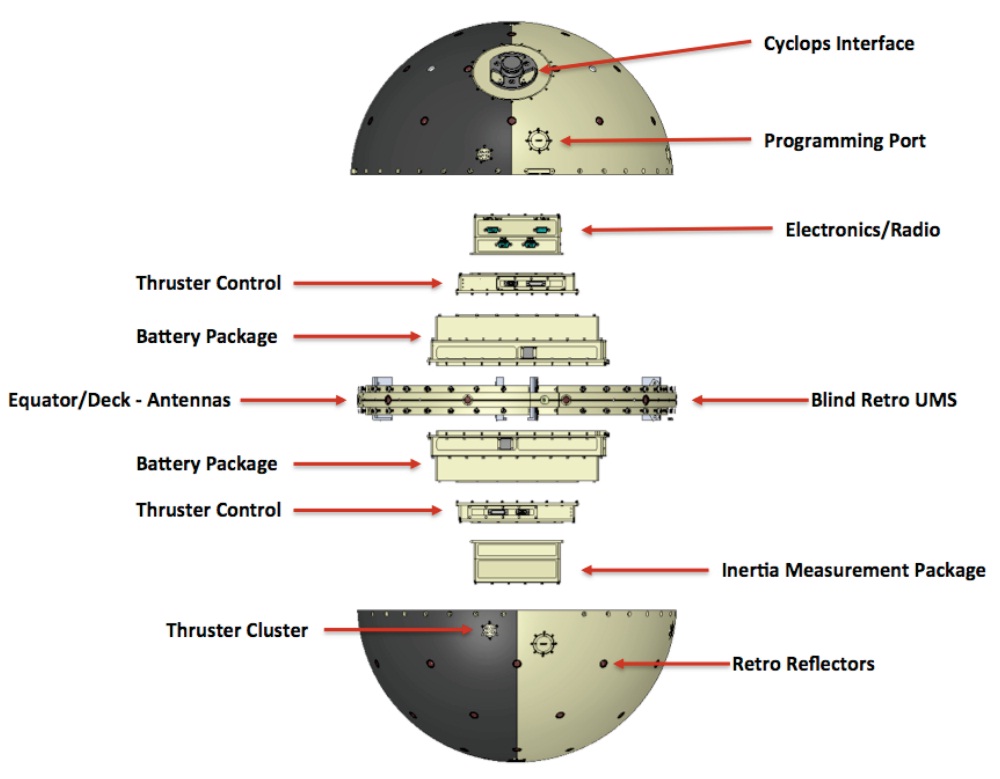
The SSIKLOPS interface is located at 45° latitude and 90° longitude. This bracket provides a structural interface, acting as a push-off point for the separation springs that are part of SSIKLOPS. The interface also includes four separation switches that, when triggered, will activate the satellite to avoid powering up the satellite before deploying since it is only powered by batteries.
The electrical system of the satellite consists of two battery packs and a power distribution system that routes power to the various satellite systems using a 5-Volt power bus. A timer board hosts three independent timers that are connected to the four separation switches through an arm plug. When the separation switches are triggered, the timers activate and initiate the power-up of the satellite and the deployment of the antennas at a specified time after release.
A discrete watchdog timer is used to re-set the satellite if the timer is not re-started in time which occurs in case of problems with the spacecraft. The heart of the satellite is the Data Handling Unit that is built around a ATMEGA1280 microcontroller that operates at low power consumption and its flight software has already been verified in space operations. The DHU supports multiple serial interfaces to exchange data and commands with the satellite subsystems, a micro-SD card is used for data storage, a real time clock triggers time-stamped commands and different interfaces are used to connect the DHU to the thrusters.
The communications system consists of a separate receiver and transmitter supporting an uplink frequency of 450 MHz and a downlink frequency of 401 MHz reaching a data rate of 9.6kbit/s. Four antennas are installed in the equator of the satellite at equal distance. The antennas are paired to create two dipoles, one for transmission one for reception regardless of the spacecraft attitude and spin rate. The antennas are made from nitinol, a flexible material that allows them to be stowed in a trough on the equator, held in place by a nylon cord that is cut by a resistor once power is applied.
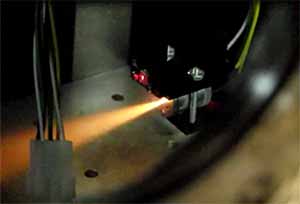
The main objective of SpinSat is the demonstration of Electric Solid Propellant Thrusters which are microthrusters than consist of two coaxial electrodes that are separated by one millimeter of Electric Solid Propellant. These propellants are a relatively new class of energetic but non-pyrotechnic solid propellants that may offer alternatives to current space propulsion systems. The solid propellant used in these thrusters can only ignite when an electric current is applied and only sustain operation as long as the current is present.
This allows for precise control and a reliable ignition. Conventional solid-fueled thrusters can not be controlled – once ignited, they burn until expending all their propellant. ESPs are an interesting alternative because they require no moving parts and their propellants are extremely safe as they are insensitive to flames or electrical sparks.
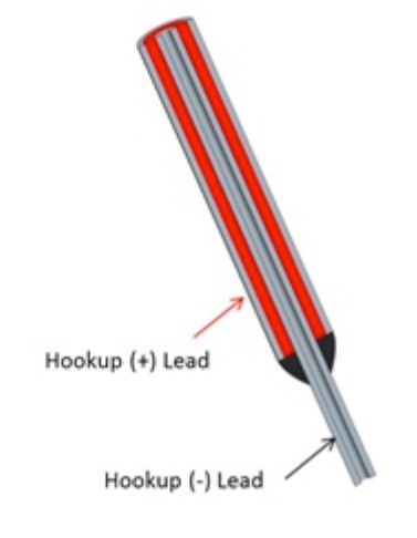
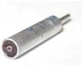
The thrusters flown on SpinSat are the first ever ESPs to fly to space. Each thruster is 13 millimeters long featuring an outer electrode tube made of aluminum and an inner electrode tube that consists of stainless steel. The space between the electrodes is filled with a total of just 0.1 grams of Electrically-controlled Solid Propellant. A key design feature of the ESP design is an insulating plastic that is wrapped around the inner electrode to create a small conductive path on the tip of the thruster. (Without the insulation, current could pass through the propellant across the entire length of the thruster and the propellant would burn uncontrollably after the current threshold is crossed.)
When a current sufficient for ignition is applied, the propellant begins burning and the plastic insulation will burn away along with the propellant to create a subsequent layer of conductive propellant. This simple solution using the insulation ensures an even burn and a flat ignition from the face of the thruster burning down to the base.
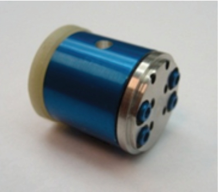
For SpinSat, six ESPs are arranged in a Universal Mounting System, UMS. A total of 12 UMS plugs are installed on the satellite for a total of 72 thrusters. The UMS plugs are identical across the satellite with the exception of flow straightener plates that are used to direct the thruster exhaust into a tangential direction for the rotational thrusters and into a normal direction for the translational thrusters.
Universal Mounting System
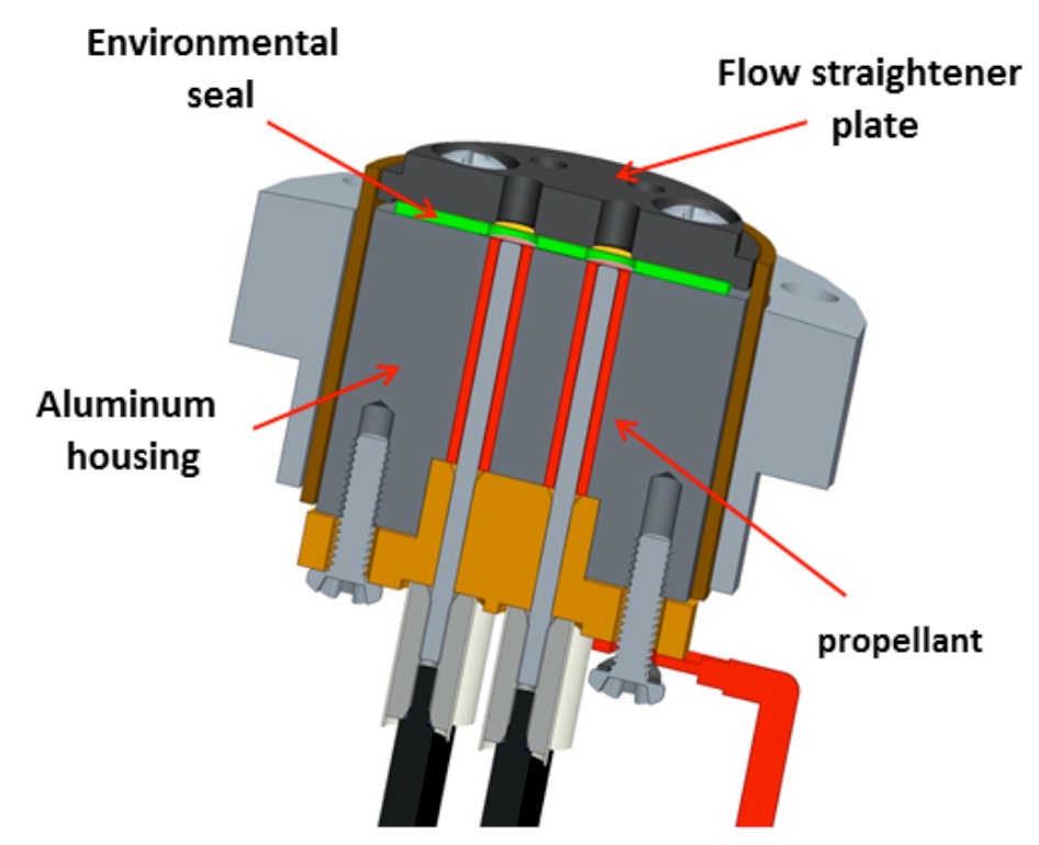
The ESPs within an UMS share their outer electrode as the entire housing consists of aluminum machined from a single piece of metal. The inner electrodes protrude from the rear of the UMS where they are connected to the cable harness. Atop each UMS is an environmental seal that protects the propellant from contaminants but also avoids any contamination of the ISS environment with propellant. This environmental seal consists of several layers of mylar, teflon, and viton.
The thrusters are actuated by a Propulsion Control Module. For redundancy, SpinSat is outfitted with two PCMs, each controlling six UMS clusters. The Propulsion Control Module is a single circuit board that contains power converters, microcontrollers for command reception and execution, communications hardware and a number of MOSFET switches that are used to address the individual thrusters since each PCM is in charge of 36 thrusters.
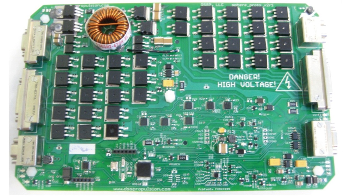
The PCMs receive a regulated power supply at 5V/0.2A which is not sufficient to activate the thrusters. Therefore, an array of capacitors is used – four tantalum capacitors are wired in series to generate 190 Volts of power to produce an ignition pulse. It takes three minutes to charge the capacitors for an ignition pulse that can be 50, 100 or 200 milliseconds in duration. The thrusters are directly connected to the PCMs via a cable harness while the PCMs interface with the satellite controller via an RS-422 link.
The ignition system is conceptualized to deal with the solid propellant’s key characteristic of having a variable electric conductivity that depends on the applied electric field, temperature, pressure and history of previous ignitions. In some cases, the load applied to the propellant will appear as short circuit which has to be tolerated by the PCM.
The microthrusters supply extremely low impulse bits with a thrust of 10-20mN. Still, the thrusters are capable of causing measurable changes in rotation on the satellite as well as translational changes. Two inertial sensors are installed on the satellite. One dedicated sensor measures the rotational motion on the z-axis while the other measures the change in translational velocity.
Ground campaigns of the International Laser Ranging Network will deliver high-resolution data that allows the determination of spin rate. A total of 68 optical Satellite Laser Ranging retroreflectors with a diameter of 12.7 millimeters are installed on the surface of the satellite along five latitudinal bands (+/-90, 67.5, 45, 22.5 and 0° in longitude with one, six, eight, ten and ten reflectors per band) and one longitudinal band of 0°.
Once the evaluation of the ESP microthrusters is complete after about four months, SpinSat becomes a passive satellite to be used for the measurement of Neutral Density in the atmosphere. As long as the satellite has battery power left, the accelerometers can be used to track microaccelerations due to drag in the uppermost atmosphere. Laser ranging will be used to accurately track the satellite’s orbital decay. Since SpinSat has a precisely calibrated ballistic coefficient, it is an excellent target for laser and radar ranging yielding high-resolution atmospheric drag data used to calculate thermospheric density.
