
IXV – Intermediate Experimental Vehicle
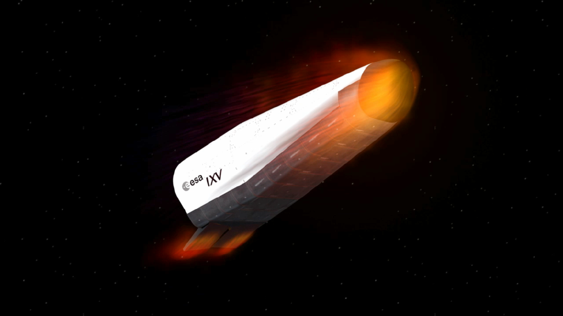
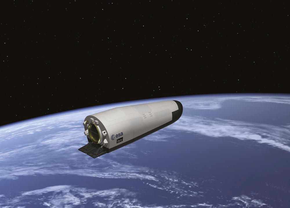
ESA’s IXV, the Intermediate eXperimental Vehicle, is a testbed for flight-testing of technologies for spacecraft re-entry. The spacecraft uses a lifting-body design with no wings, a thermal protection system, and two flaps that are used to provide control during re-entry.
IXV performs a sub-orbital test mission in February 2015 to gather data on the behavior of the various systems and components in the operational re-entry environment to pave the way for the development of new innovative spacecraft with return capability.
- The main elements that are demonstrated by IXV include the development of a system capable of returning from Low Earth Orbit with a lifting system that is capable of reaching a large down range distance with significant cross-range capability using a combination of rockets and aerosurfaces. As its first mission, a sub-orbital flight with a re-entry velocity of 7.5 Kilometers per second was chosen which fully represents a re-entry from orbit that occurs at speeds of just a few 100m/s higher.
-
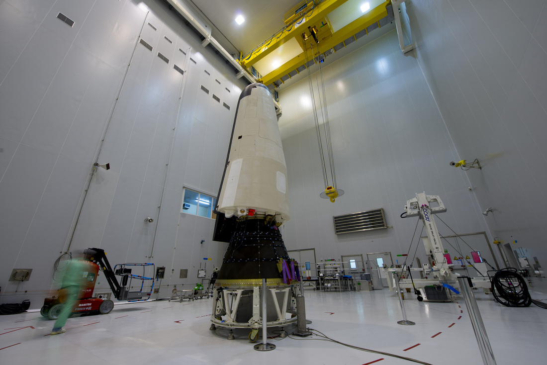
Photo: ESA The key technologies demonstrated by IXV include Thermal Protection Systems (TPS), operation in Aero-Thermodynamic environments (ATD), and Guidance, Navigation & Control (GNC).
The IXV spacecraft is 5 meters long, 2.2 meters wide and 1.5 meters high with a launch mass of 1,845 Kilograms and a lift-to-drag-ratio of 0.7. It consists of a number of large components – an inner body assembly with a number of inner bays, a base assembly, a lateral assembly, a leeward assembly, a windward assembly, a nose assembly and a flap assembly.
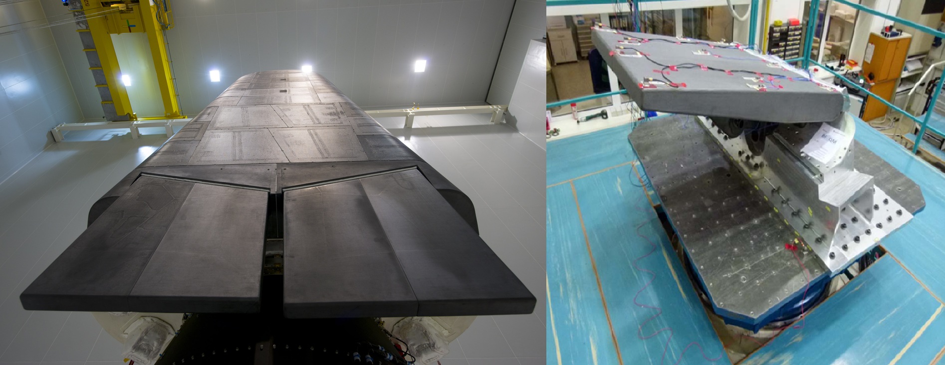
The outer surface of the vehicle consists of advanced ceramic and ablative thermal protection materials that are able to withstand the extreme thermo-mechanical environment encountered during re-entry to protect the vehicle’s structural integrity and functionality throughout the re-entry process.
The structural elements of the inner body segment are comprised of advanced carbon fiber reinforced polymers forming structural panels that provide the stiffness and strength to support the components of the vehicle during ascent, orbital flight, re-entry and splashdown in the Ocean.
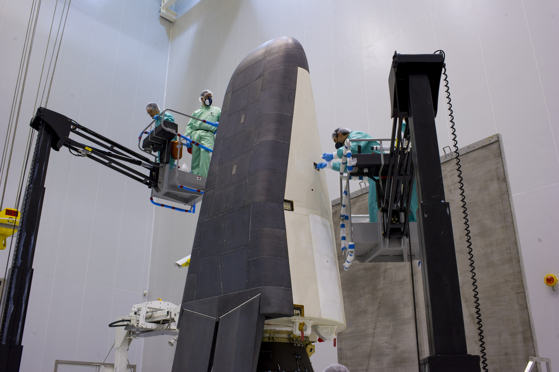
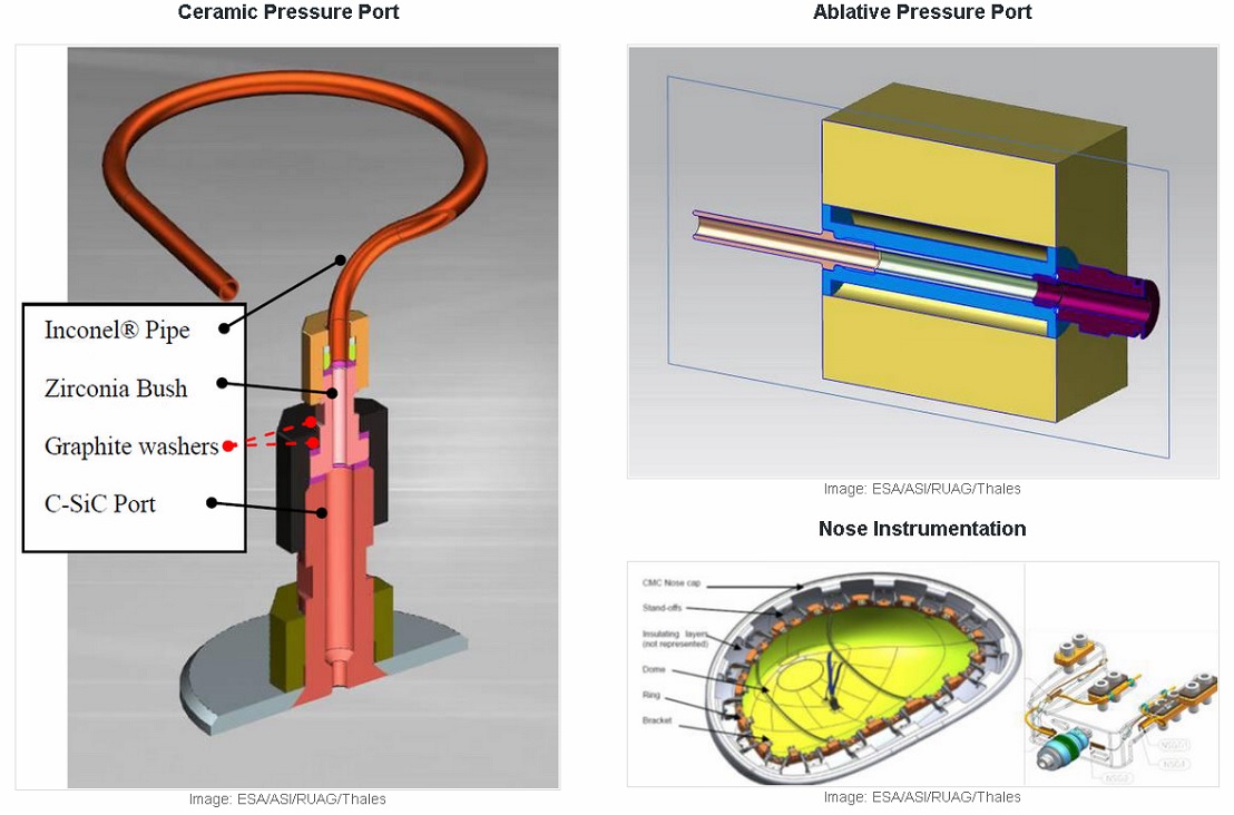
The windward assembly is protected by ceramic matrix composite C-Si-C panels with lightweight ceramic insulations (alumina, silica), and attachments that are made of superalloy bolts, flexible stand-offs, ceramic thermal barrier washers and ceramic fiber seals. The nose assembly is derived from technology used on the windward assembly, also employing silicon carbide materials.
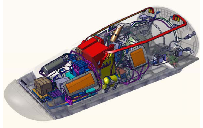
From the front to the rear, the IXV spacecraft hosts a number of different systems – the avionics consisting of power, data handling, telemetry equipment and various electronic controllers; the parachute and flotation systems; and the control actuators in the aft of the vehicle such as the electromechanical systems to control the flaps and the propulsion module and various thrusters.
The lateral and leeward assemblies use an ablative thermal protection system with an external coating providing antistatic properties and appropriate thermo-optical characteristics. The individual tiles are bonded together using an epoxy-based structural adhesive with gaps in between tiles sealed with a filler made from the same adhesive mixed with cork granules which avoids thermal ridge effects.
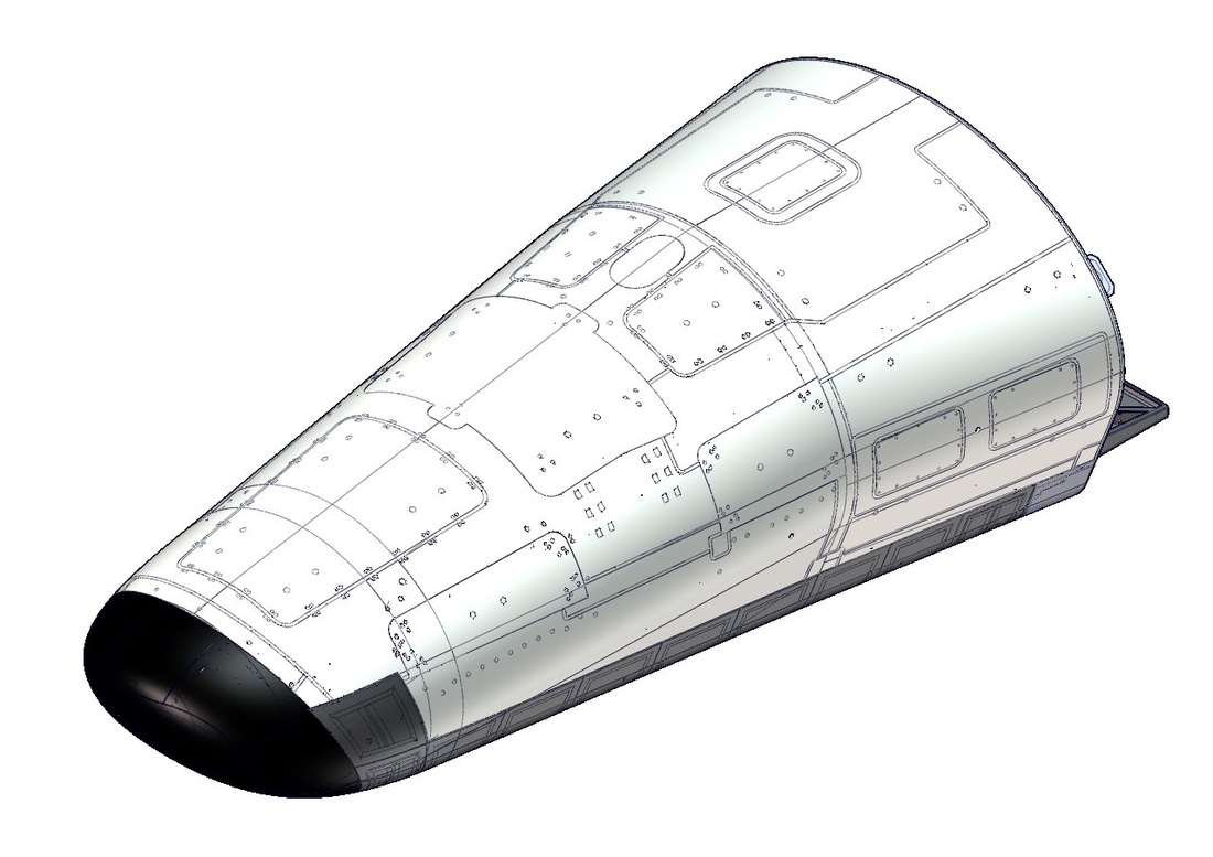
Nose Cone Construction & Leeward Assembly Heat Shield
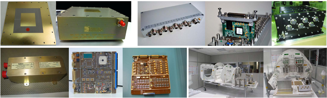
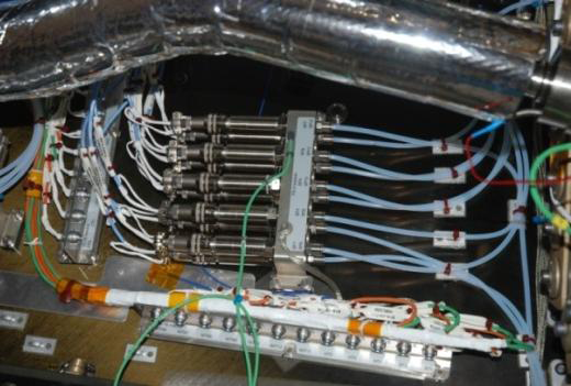
The Electrical Power Subsystem consists of a Power Protection and Distribution Unit, two separate batteries and two dedicated pyro batteries, all using Li-Ion technology. The PPDU conditions a 28-Volt main power bus that is provided to all the subsystems of the spacecraft using a redundant architecture. A single 55-Volt power source is provided to the Inertial Measurement Unit. The PPDU also includes the RCS Driver and the Pyro Driver – the RCS driver controls the Flow Control Valves of the four thrusters as well as two latch valves while the Pyro Driver is connected to the two pyro batteries, conditioning the pyro power bus that is connected to the pyro valves of the Reaction Control System, the parachute pyros, the panel pyros and the flotation device. The overall power system architecture of IXV uses heritage from the Gaia, Sentinel-1 and ATV programs.
Electrical Power System Components
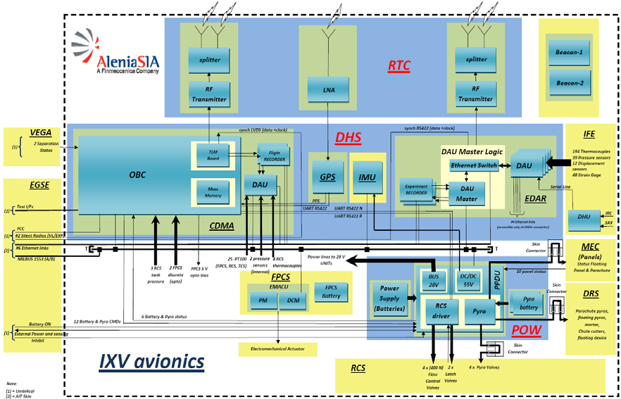
The Data Handling Subsystem of the IXV spacecraft consists of two elements – one handling spacecraft telemetry and commands, and one collecting data from the experimental flight sensors. The brain of the spacecraft is a central Onboard Computer using a LEON-2 microprocessor that is in charge of the execution of the flight software and the control of all mission tasks. The data system includes a number of redundant data recorders that are in charge of storing telemetry and experimental data sourced from a series of Data Acquisition Units based on a finite state machine design.
The data and command system of the spacecraft uses a combination of Ethernet and serial connections handling different data volumes throughout the mission with the primary objective of sustaining the data flow without overloading any systems. Serial links used on the spacecraft include a MIL-STD-1553 bus that builds the central link for commands and systems telemetry with an RS-422 bus used in certain interfaces.
The Onboard Computer is a radiation tolerant unit operating in a single-chain configuration using a LEON2-FT Central Processing Unit operating at 50MHz. The OBC is in charge of all in-flight operations including the execution of Guidance, Navigation and Control tasks, the issuing of pyro commands and actuator commands. It is also in charge of encoding the Vital Layer Telemetry and storing it onboard as well as downlinking it to the ground.
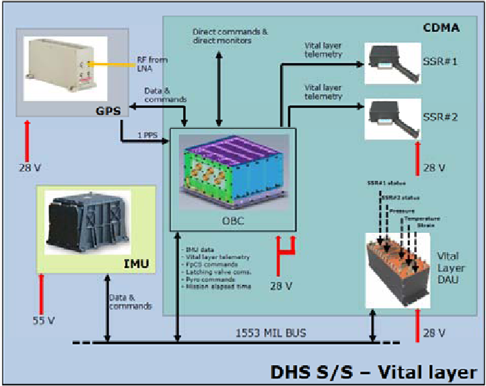
The Vital Layer in the data system represents the systems in charge of actual spacecraft tasks such as GNC operations, and systems telemetry recording in two redundant recorders. Vital layer telemetry is collected by the Onboard Computer from the 1553 data bus that feeds data from the Inertial Measurement Unit, data from five Data Acquisition Unit that includes telemetry from all subsystems, and GPS data. Data is stored in two Solid State Recorders each with a capacity of 24GB.
The Experiment Layer is dedicated to the management of the in-flight experiment data generated by hundreds of sensors installed across the IXV. The system also uses a store and play-back mechanism that downlinks data in real time when a ground station is visible and plays back stored data from periods of Loss of Signal.
Guidance and navigation data for IXV is provided by a Quasar 3000 Inertial Measurement Unit and a Global Positioning System receiver. The Quasar 3000 is a strapdown navigation platform based on linear accelerometers and ring-laser gyros that provide precise rotation measurements. Attitude data is delivered by the gryos while the local acceleration is delivered by the accelerometers and provided to the onboard computers as inertial attitude frames and delta-velocity measurements about the three axes. The IMU delivers data at a speed of 100Hz through the 1553 data bus.
The GPS system consists of an antenna system connected to Low Noise Amplifiers that use a radio connection to the main GPS processor that delivers timing and position data to the Onboard Computer. Timing data is provided to the OBC by means of a 1 Pulse Per Second signal with a 100 nano-second accuracy while position data is delivered at a frequency of 1Hz via a serial RS-422 link.
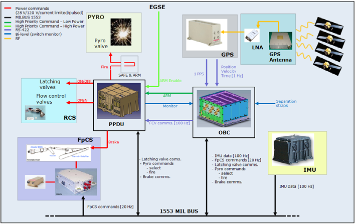
IXV Functional Block Diagram
Flight Control on IXV is accomplished by using 400-Newton reaction control thrusters and two aerodynamic body flaps installed on the back of the windside assembly. The four thrusters are installed on the base of the vehicle to provide three-axis control during orbital flight.
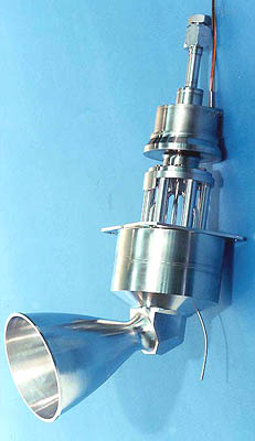
The 400N thrusters are manufactured by Airbus Defence and Space and have been used in previous re-entry demonstrators as well as all Ariane 5 upper stages. It can be operated in steady state mode and pulse mode to be able to provide small attitude maneuvers as well as larger translational maneuvers.
The combustion chamber and nozzle are manufactured from Haynes 25 alloy with the engine structure serving as a heat barrier for protecting the spacecraft structure. The thruster uses the catalytic decomposition of hydrazine monopropellant over a heated catalyst bed with redundant heater units.
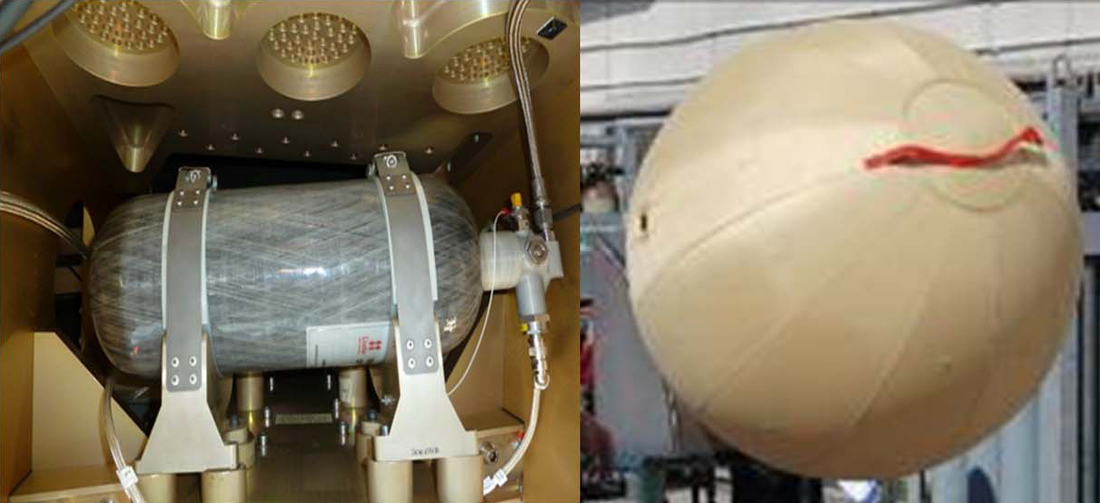
The thrusters are fed from a single titanium tank with propellant lines including pyrotechnic latch valves. The 400N thruster is 32.5 centimeters in length with a nozzle diameter of 6.7 centimeters and a mass of 2.7 Kilograms. Operating in blowdown mode, the thruster can tolerate inlet pressures of 6 to 26 bar and is capable of delivering 130 to 455 Newtons of thrust corresponding to specific impulses of 214 to 224 seconds. The flow control valves of each thruster are operated on command from the onboard computer through an RS-422 link.
The thrusters are used to provide three-axis control during orbital flight and yaw control through the re-entry process while also complementing the two aerodynamic flaps in controlling the pitch and roll during re-entry.
Thrusters & Flap Control System
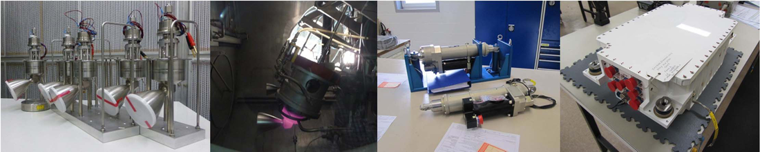
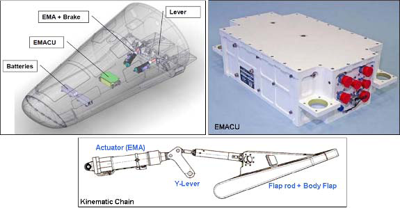
The Flap Control System is in charge of providing the motion and controlling the position of the two flaps during re-entry, becoming active when the efficiency of the aerodynamic control surfaces increases with the dynamic pressure. The electromechanical control system is a derivative of the Zefiro Thrust Vector Control System employed by the Vega rocket.
The two flaps can be controlled through the elongation and retraction of the two electromechanical actuators. These commands are issued by the onboard computer to the EMA control unit through the 1553 bus with EMA converting the commands to mechanical outputs of the actuators. Two batteries are used in parallel to provide the power needed for the EMA movement.
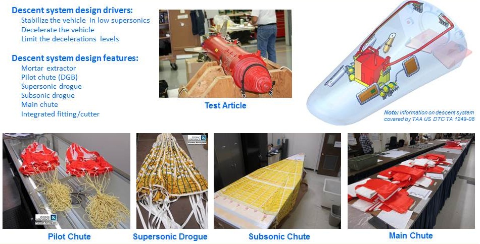
The guided re-entry performed by IXV delivers the spacecraft to an altitude of 26 Kilometers traveling at a speed of Mach 1.45 at which point the vehicle initiates the deployment of its parachute system consisting of three stages. Since the primary purpose of the IXV mission is to only demonstrate the re-entry system and all of its elements, ESA decided not to invest in developing a one-off parachute system, instead procuring an off-the-shelf system suitable for the needs of the IXV spacecraft. First, a Disk Gap Band Pilot Parachute is deployed from a pyrotechnic mortar. The Pilot Chute has been adapted from NASA’s Mars Missions. The chute has a diameter of 1.7 meters designed to fully inflate within two seconds to pull the supersonic drogue chute out of its parachute bag.
The 4.3-meter drogue parachute is based on the aero-brake parachute of the U.S. F-117 fighter. The drogue chute stabilizes the vehicle during the transonic transition, slowing the spacecraft down to Mach 0.3 at an altitude of ten Kilometers which is safe to deploy the main parachute, a 7.4 meter ribbon chute that is used on the F-111 fighter cabin crew escape system.
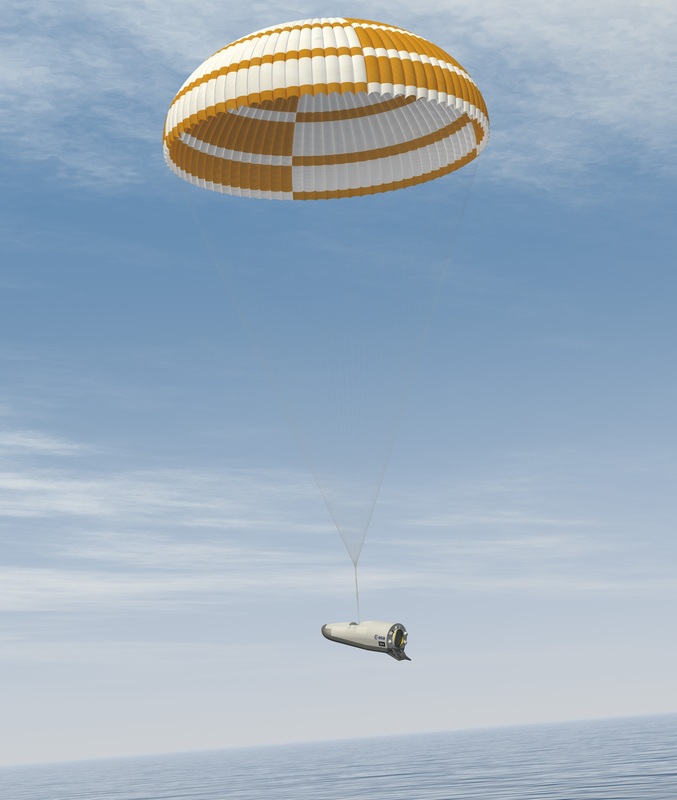
During the second stage of its descent under the parachute, IXV transitions to a vertical descent, reaching an altitude of five Kilometers and a speed of Mach 0.12 when the third chute is deployed, measuring 29.6 meters in diameter – one of the largest ring sail chutes ever designed. It has been used on the Mars Science Laboratory mission to slow the Curiosity rover down when making its descent to the surface of Mars.
The final chute utilizes reefing stages to reduce the maximum force acting on the vehicle to 3.7 Gs. Initially, the chute will be flown at a 10% reefing stage for ten seconds before being fully inflated to slow the spacecraft down to 6 meters per second for splashdown.
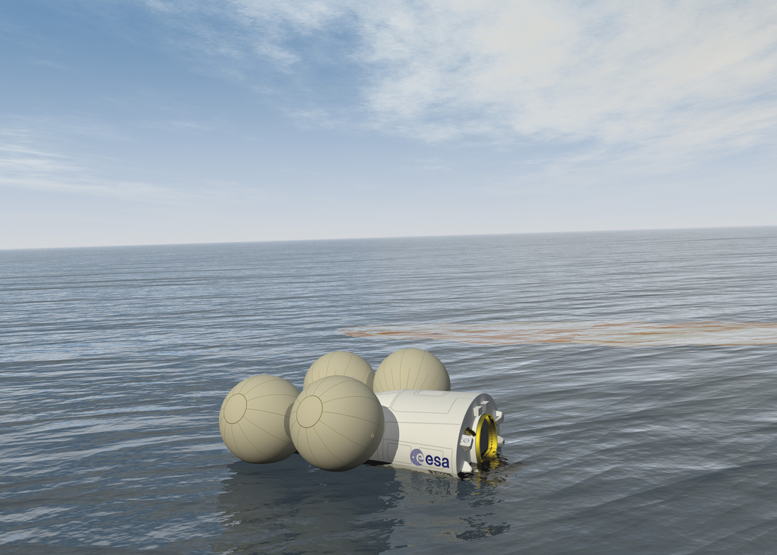
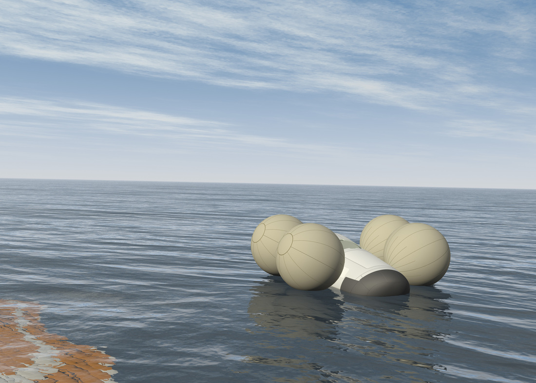
IXV uses a flotation system manufactured by Aero Sekur consisting of four large airbags that are inflated immediately after the Inertial Measurement System senses splashdown in the water. Each bag has a volume of 0.8 cubic meters deployed from a carbon fiber reinforced ply section using independent gassing elements to inflate the airbags which have been designed to take a shape that optimizes the vehicle’s stability during flotation. The system has been designed to keep the spacecraft afloat for 48 hours in order to allow an extended recovery operation.
Flight Test Instrumentation
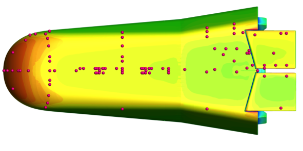
Since the purpose of IXV is purely a technology demonstration mission, it is outfitted with various sensors to record all environments that the vehicle goes through during its flight and the response of the different structural systems with particular attention paid to the thermal protection system. In total, IXV hosts 37 pressure sensors, 194 temperature sensors, 12 displacement sensors, 48 strain gauges and advanced sensors such as an infrared camera. The sensor suite is split in two main areas – the aerodynamic and aero-thermodynamic (AED/ATD) experiments that look at aero-thermal phenomena occurring at the different stages of re-entry, and Thermal Protection System experiments that focus on the validation of insulation capabilities of the TPS during entry.
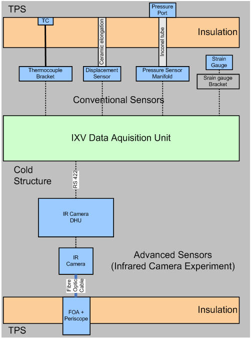
The overall architecture of the experiment system installed on IXV consists of two segments – conventional sensors such as thermocouples, pressure sensors, stain gauges and displacement sensors, and advanced sensors comprised of an infrared camera.
The conventional sensors deliver raw data straight to four Data Acquisition Units that are just a group in several DAUs installed on IXV and plug right into the core data system of the spacecraft, feeding the experimental layer described above, returning telemetry to the ground and recording all parameters on board for later downlink or post-landing read-out. The advanced sensors require onboard processing of signals in a dedicated Data Handling Unit prior to transmission to the vehicle via an RS-422 interface.
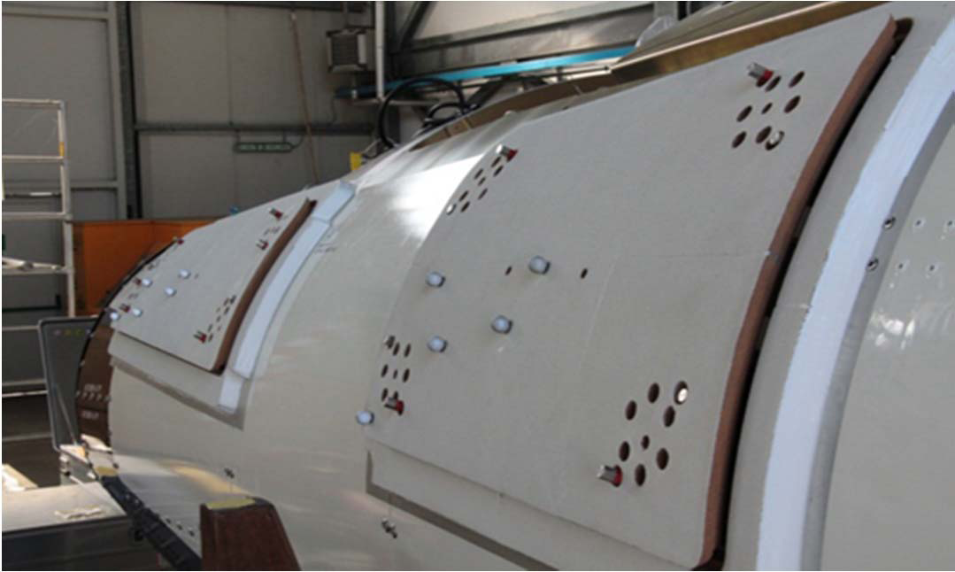
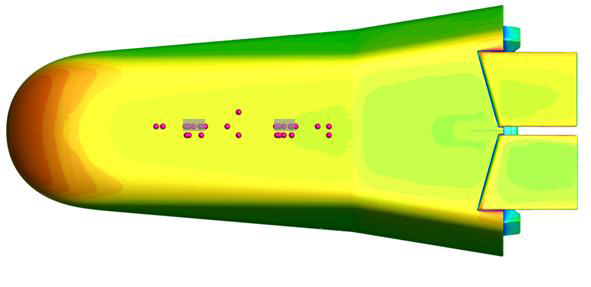
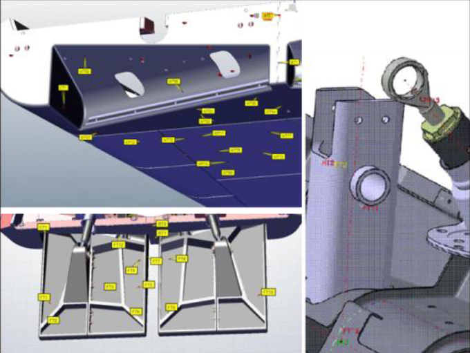
Windward Assembly Temperature Sensor Locations
Each of the four DAUs include recorders that store telemetry that is also sent to the solid state recorders of the vehicle and downlinked to the ground, building a system with several redundancies to ensure data will be available – either through real-time downlink, stored data playback or retrieval from onboard recorders post-flight.
The conventional sensors are divided in three types based on their installation location – thermocouples and pressure ports on the thermal protection surfaces, bracket located sensors such as strain gauges and interior sensors mounted on cold surfaces.
All in all, IXV hosts 105 Type-S Platinum thermocouples, 89 Type-K thermocouples, 37 absolute pressure sensors, 2 differential pressure sensors, 12 displacement sensors, 48 strain gauges and one Infrared Camera System. The purpose of each sensor group is described later on, first looking at the functionality of each of the different sensor types.

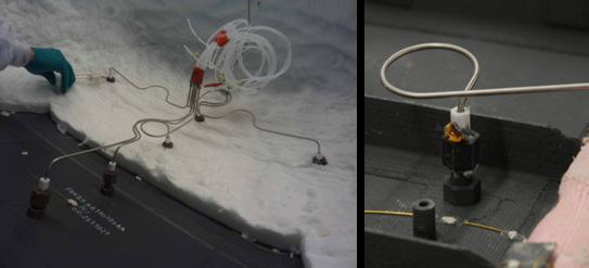
The pressure ports on the nose and windward assembly are installed in different inclinations to allow the monitoring of skin friction effects. To ensure the performance of the thermal protection system, the holes and interfaces for the pressure ports were built-in from the start by the TPS manufacturer because the ports represent a direct link between the hot plasma environment and the interior of the vehicle, creating large thermal gradients and thermo-mechanical loads. The ports were designed to be able to withstand all re-entry heat loads without stressing the surrounding ceramic material.
The pressure ports, themselves consisting of silicon carbide, use a stabilized zirconia ceramic section as insulator to avoid a heat transfer to the interface structure in the interior of the vehicle. The insulator is decoupled from the vehicle by compressed graphite washers that also dampen movement and vibration of the pipe during the entry and launch environments.
The pipes connecting the ports to the sensors are four millimeters in diameter and consist of Inconel when being routed on the ceramic fiber insulation and changing to Teflon on the inside of the vehicle. The pipes are bent which allows for the compensation of thermal expansion between the fixation points that will exhibit thermal gradients of up to 860K.
Pressures are sampled every 100 milliseconds, amounting to ten measurements each second. The hydraulic delay of the piping has been analyzed to be less than the sampling interval and can therefore be accepted without correction.
The pressure ports installed on the ablative heat shield sections feature a zirconia tip that crosses the ablative material to a metal insert which, on its other end, interfaces with a Teflon pipe through a coupling interface. The rest of the sensor is identical to the pressure sensors installed in the ceramic TPS.
 The displacement sensor system is used to measure the evolution of steps between the adjacent TPS units. Particular attention is paid to the step between the nose and the windward assembly due to the high thermal stress this region experiences. The displacement sensors are designed to be placed on the outer surface of the vehicle and penetrate the plasma seals. Each sensor integrates a Linear Variable Differential Transformer-type sensor in an aluminum housing with a stroking element made of ceramic material with low thermal conductivity and extremely low thermal expansion. The maximum stroking distance for each sensor is +/-5mm and the resolution of measured movements is 0.2mm. To smoothen the surface of the thermal tiles, an adhesive layer is placed on the tile.
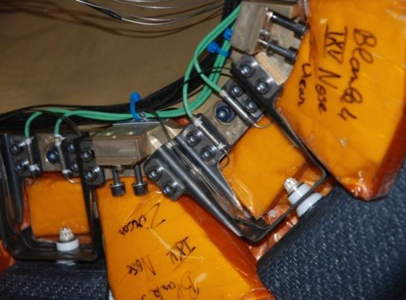
The strain gauges represent the second type of mechanical sensing element used by IXV. They are used to measure the forces on the metal stand-offs on the nose cone and the windward thermal protection system. Given their installation location, the strain gauges have to be able to withstand high temperatures. 10mm long temperature compensated strain gauges are installed on IXV with an operational limit around 750°C. The sensors host an Inconel sheath that allows them to be welded to the brackets. The gauges use a half bridge sensor with a resistance of 120 Ohms and a strain limit of +/-10,000 micrometers per minute. A dummy element is used for thermal compensation.
Four strain gauges are used per bracket to allow a clear distinction between bending, torsion or unidirectional loading. Due to the sensor design, the strain gauges had to be placed on flat areas although curved elements experience higher strains. The sensors interface with coupling connectors and the cables use a Wheatstone bridge for temperature compensation of the measure strain. Temperature monitoring of the stand-offs is accomplished by spot-welded Type-K thermocouples.
The Infrared Camera represents the advanced sensor flown on IXV, installed on the zenith-facing side of the base panel looking down on the backside of the vehicle to be able to map the thermal evolution of one body flap for its whole deflection range at a sampling rate of 25 Hz. The near infrared camera uses periscope optics consisting of a sapphire mirror with a narrow band coating to observe the flap area through a fiber optic waveguide that allows the placement of the infrared sensor inside the vehicle.
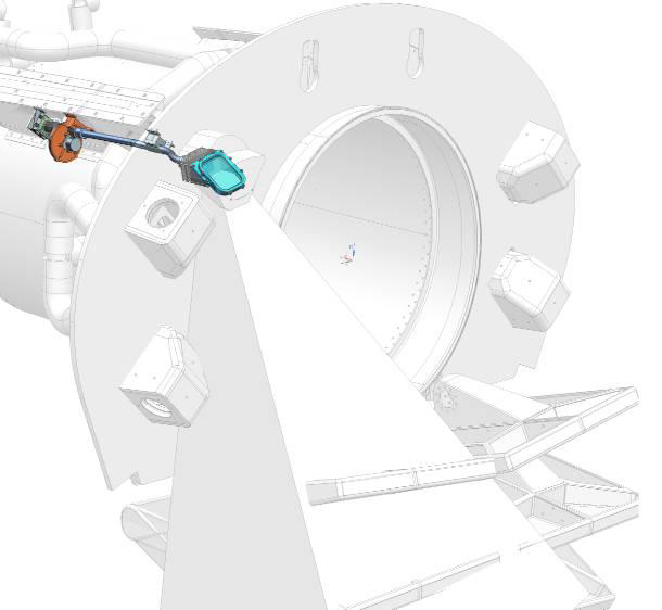
IR Camera System & Field of View
The IR sensor is relatively small at 320 by 256 pixels. The camera uses a filter wheel with three optical filters to allow an independent measurement of temperature and emissivity to be able to correct for the angular position of the flaps as well as hydrazine and ablative soot contamination that occurs over the course of re-entry. Inverse methods are used to retrieve the windward temperatures from IR imagery.
The IR camera delivers data to a central data handling unit that includes all power regulation and distribution required for the camera, analog to digital converters, a central processor, a set of solid state recorders and an input-output interface. The electronics box uses four cards facilitating the different functions. Ground-based processing of data will allow a calculation of the flap deflection angle with an accuracy of 0.1 degrees.
The IR camera employs an onboard algorithm that analyzes the grey level content of the images to adjust the exposure time of the camera. Exposure speed adaptions will allow the measurement of temperatures from 300 to 2,000°C with an error of 10K. Imagery generated by the camera is stored in the data handling unit and downlinked to the ground after going through a bandwidth reduction to satisfy the telemetry budget.
The various sensors are used to characterize the re-entry environment that IXV experiences and record the response of the various systems to that environment with particular interest in the thermal protection system and the steering flaps. A number of experiments have been developed using all or a subset of the sensors to derive relevant parameters needed for a full characterization of vehicle performance.
The Laminar-to-turbulent Transition experiment consists of 34 Type-S thermocouples installed in longitudinal and spanwise arrays on the heat shield to detect temperature jumps as the result of an increase in convection heat flux during the turbulent transition which occurs due to a change in Reynolds number. This rise in the Reynolds number occurs as the air density increases when the spacecraft dips into the atmosphere while the speed decreases much slower so that a laminar flow to turbulent flow transition occurs. In addition to the temperature sensors installed on the vehicle, the experiment also includes six displacement sensors that will detect the size of the steps that could trigger a transition in critical areas of the heat shield.
CATE Sensors
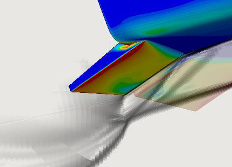
Shock Wave / Boundary Layer Interaction on Steering Flap
The Materials Catalytic Behavior Experiment studies dissociation-recombination processes occurring within the boundary layer formed on the heat shield in a highly dissociated flow. It uses a catalytic mullite layer applied on a low catalytic surface (the C-SiC TPS in this case) which will allow the detection of the temperature jump and therefore allow the confirmation of the catalysis behavior of the ceramic material. The experiment consists of 30 Type-S thermocouples that are placed downstream from the two coated surface elements located in the center of the windward assembly. These sensors will allow a detailed characterization of the temperature increase across the patches.
Another experiment is the Shock Wave – Boundary Layer Interaction and Flap Aero-thermodynamic Experiment. This study sets out to examine the complex aerothermodynamic processes occurring on the flap surface and surrounding volume after the generation of the shock waves induced by flap motion. In the event of high flap deflection, the shock forming upstream the flap hinge will induce a separation and reattachment shock – a phenomenon that is hoped to be characterized with this experiment since it has a significant effect on the efficiency of the flap system. 21 Type-S thermocouples are installed in the hinge-flap zone and on the flaps themselves to provide a full coverage of the thermal evolution in that area relative to the external environment of speed and air density. An infrared camera placed on the base of IXV monitors the temperature on the leeward side of the flaps to contribute to this study. Four pressure sensors are placed upstream of the flap to provide data on the extent of the shock separation.
The General Heating Experiment investigates the evolution of global heating at the surface of the vehicle during the hypersonic phase of the re-entry which covers the continuous flow plus laminar and turbulent regimes. The experiment uses all thermocouples installed on the spacecraft and combines data from the various other experiments to obtain a global map of thermal evolution during entry, identifying particular areas that experience more significant heating.
The Flush Air Data System aims to derive precise vehicle attitude in the form of angle of attack, angle of sideslip and atmospheric properties from pressure and temperature measurements taken at the nose of the vehicle. The sensors are arranged in a cross array in order to maximize gradient readings. Data analysis will confirm whether this type of measurement can allow the extraction of the relevant quantities which would make this system suitable for future application on re-entry vehicles.
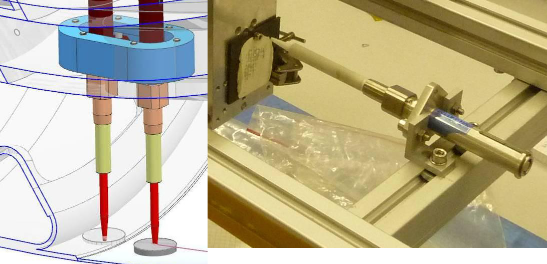
The Slip Flow and Skin Friction Experiment aims to asses the local aerodynamic characteristics at the wall in both the high-altitude range in the transition regime between the free molecular flow and the continuum flow and in the continuous flow regime itself. The system uses differential pressure measurements to attempt to deliver the slip flow velocity in the transition regime and the skin flow velocity in the continuum regime. To obtain these measurements, the instrument consists of a pressure sensor with an aperture perpendicular to the surface connected to an absolute and differential pressure sensor inside the vehicle, and another sensor port with inclined aperture that is connected to the other side of the differential pressure sensor. A thermocouple is located in the vicinity of the sensor ports. The experiment looks at the front of the windward tiling and the middle of the vehicle.
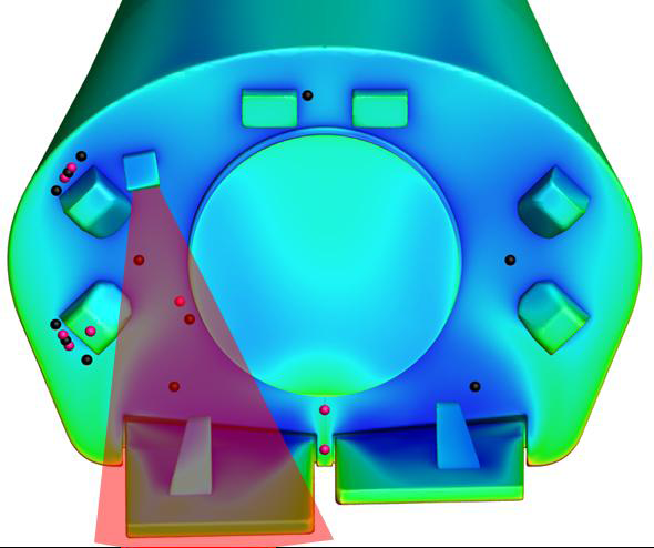
Base Area Sensors & Steering Flap Instrumentation
The Continuum Flow Experiment looks at the aerodynamic properties in the continuous regime including the aerodynamic coefficients, the flap trimming deflection and flow characterization through pressure mapping. The experiment uses all surface pressure measurements and GNC data collected during re-entry.
The High Altitude Aerodynamics Experiment determines the aerodynamics coefficient in the high-altitude, rarefied/transitional regime. The estimation will be done by using data collected by the accelerometer of IXV. An actual measurement of the coefficients through acceleration is not directly possible, requiring an estimation through the ratio of normal and axial forces.
The Jet Flow Interaction experiment aims to address the interaction between the thruster generated jet and the external flow with particular interest in plume spreading and plume impingement on the base wall of the spacecraft. The efficiency of the thruster can be derived from the acceleration and angular rate measurement during the activation of the 400-Newton thrusters. These measurements are performed within the GNC system of the vehicle while the interaction of the plume and the vehicle surface is measured with temperature and pressure sensors that are making measurements perpendicular to the jet axis.
The Base Flow Field Experiment uses a series of sensors on the base of the vehicle to deliver data on the separated base flow in the various re-entry environments which is hard to model and often leads to large errors in the estimation of the drag coefficient and other parameters when only using computational data. Having actual measurements from the hypersonic down through the velocity range of entry will result in an improvement of models and a reduction in the misprediction of pressure field in the low supersonic regime and a reduction in the overestimation of the heat flux in the hypersonic regime.
The Gaps and Cavity Heating experiment examines the local aerothermodynamics in cavities and potential sneak flows that could be induced by pressure gradients under imperfect sealing. Two cavities are the focus of this investigation – the hinge cavity closed by a seal in depth and the open flap side cavity between the flap hinge and hinge TPS. The experiment consists of several thermocouples with pressure data being used from the continuous and base flow experiments.
The infrared camera system delivers an accurate mapping of real time temperature distribution in the flap area that is subjected to high gradient, rapid fluctuating aerothermodynamic effects such as the reattachment flows and trailing edge and cavity heating. A number of thermocouples within the field of view of the camera provide temperature references and can be used for recalibration of the IR camera.
The Thermal Protection System Experiments evaluate the various components of the TPS in the different re-entry environments looking at the ablative leeward and lateral surfaces and the two different types of silicon-carbide used for the hotter parts of the vehicle such as the nose cap, the flaps and rear hinge compared to the rest of the vehicle windward tiling.
The deflection of the edges of the TPS tiles is measured using linear variable differential sensors. This deflection is caused by the large thermal gradients and pressure loadings that the different areas of the windward assembly are subjected to, causing changes in surface topology and high transient loading of fixation elements potentially leading to positive steps inducing local aerothermodynamic effects with increased thermal loads to neighboring tiles. The aerodynamic and thermal loads on the TPS as well as the deflection and the evolution of positive steps is measured as part of the experiment using a combination of strain gauges and thermocouples that are placed at the metal stand-offs behind the highest loaded tiles and on the nose cap attachments.
Another objective of the system is the verification of the silicon carbide flaps in a realistic flight environment. This is achieved through the use of data from the various thermocouples in the windward assembly as well as the IR camera at the base of the vehicle. Thermocouples are placed at different depths of the Thermal Protection System to allow the determination of heat fluxes and ablative performance. Areas where two different types of TPS are in contact with each other (nose to tile, windward to lateral tile, nose cap to ablator, between tiles) feature sensors on each side in the two different materials to be able to evaluate surface mismatches and the resulting overheating.
Mission Profile
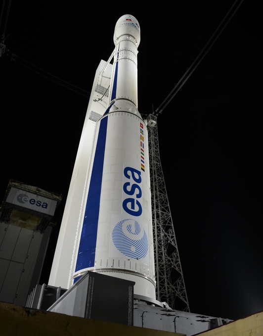
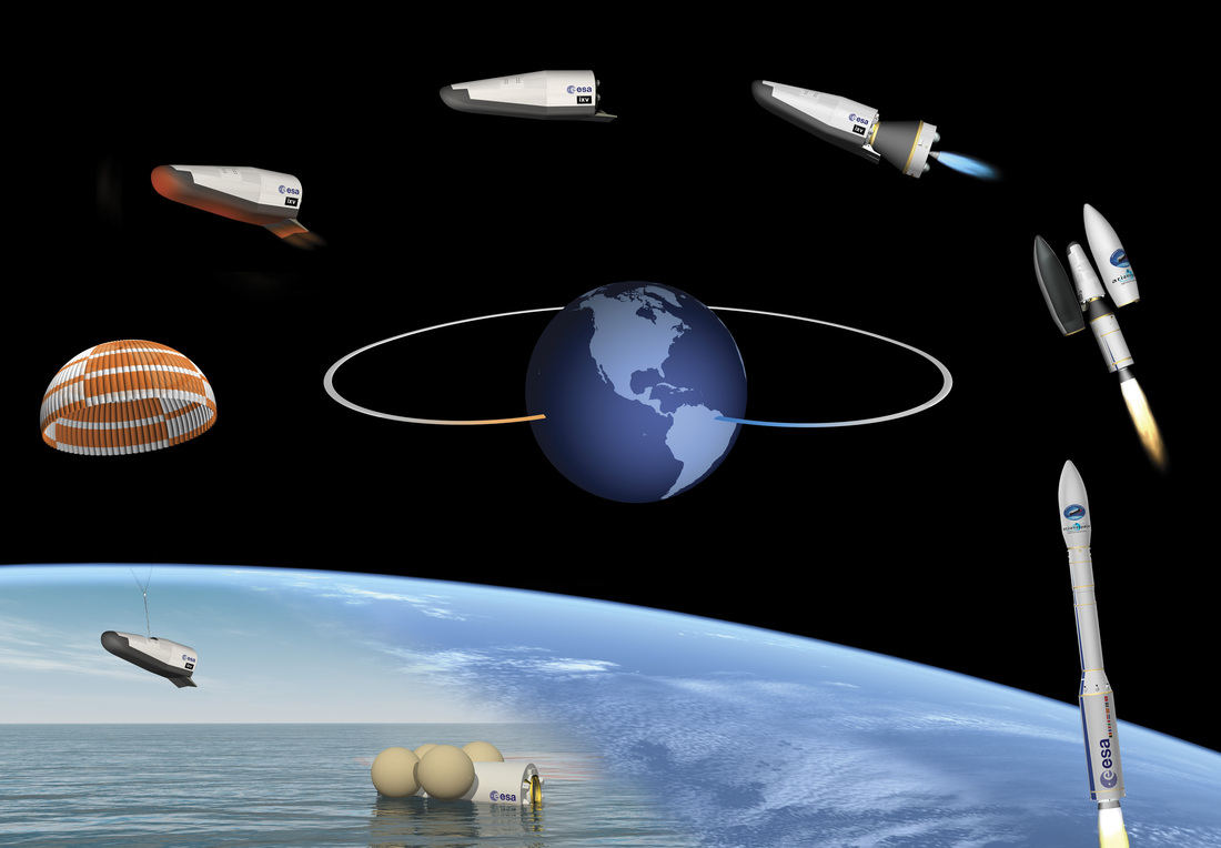
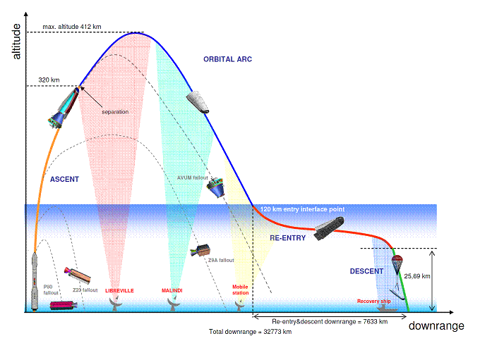
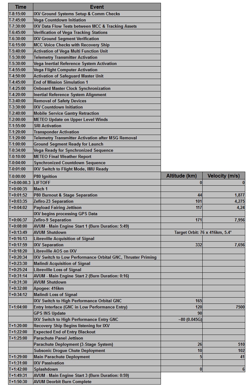
IXV is launched aboard ESA’s Vega rocket on a sub-orbital trajectory that allows the vehicle to conduct a re-entry that resembles a re-entry from Low Earth Orbit as closely as possible. The trajectory chosen for the mission delivers IXV to an apogee of 416 Kilometers before the spacecraft begins its way back down towards the dense atmosphere, reaching the atmospheric entry gate at 120 Kilometers in altitude at a velocity of 7.5km/s and a flight path angle of –1.2 degrees fully representative of a re-entry from Low Earth Orbit that occurs at a speed of a few hundreds of meters per second higher. Overall, the mission takes IXV from its launch pad in South America almost an entire lap around Earth for a parachute-assisted splashdown in the Pacific Ocean 100 minutes after liftoff.
Prior to launch, IXV is powered up for final testing activities and reconfigurations for its flight with its flight computer being enabled to run through a series of different GNC modes over the course of the mission taking the vehicle from Pre-Launch to Post-Splashdown. Operation in pre-launch mode is focused on the Inertial Measurement Unit of the spacecraft which completes final calibrations. Prior to launch, IXV switches to internal power.
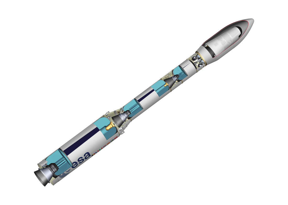
The Vega launch vehicle made its first flight in 2012 as the lightest in the family of launch vehicles operated by Arianespace, entering service alongside the medium-lift Soyuz and the heavy-lift Ariane 5 rockets. Prior to IXV, Vega made three successful launches as part of the VERTA certification program.
Vega is a three-stage launch vehicle using all-solid stages and an additional liquid-fueled fourth stage known as the Attitude Vernier Upper Module, AVUM, that gives the vehicle the ability to target a range of orbits and conduct precise orbital insertion maneuvers. Overall, Vega stands 29.9 meters tall with a diameter of 3.03 meters and a launch mass of 137 metric tons. It can deliver up to 2,500 Kilograms into Low Earth Orbit.
Being a solid-fueled vehicle with an upper stage that uses storable propellants, Vega’s countdown is not as complex as that of other launchers since no dynamic events such as tanking are required. The countdown includes a full checkout of all subsystems of the launch vehicle including the Flight Control System and reconfigurations of said system to transition the vehicle into a launch configuration.
Liftoff of Vega and IXV is targeted for 13:00 UTC on February 11, 2015 with a total launch window duration of 1 hour and 43 minutes driven by day length at the recovery location to ensure a successful recovery of the spacecraft in the Pacific Ocean after its flight. The nominal length of Vega’s mission from launch to IXV separation is 17 minutes and 59 seconds.
Upon ignition of the P80 first stage, Vega jumps off its launch pad with a total thrust of 230,600 Kilogram-force, starting a short vertical ascent before making a pitch and roll maneuver to start heading east-north-east – headed for a nearly equatorial orbit, a first for Vega which explains why additional time was needed to verify the trajectory and associated safety requirements prior to the launch of IXV. The first stage of Vega burns through 88,365 Kilograms of solid propellant operating at a chamber pressure of 95 bar to deliver 2,261kN of sea level thrust. The stage is 11.2 meters long and employs an electromechanical thrust vector control system for vehicle stabilization.
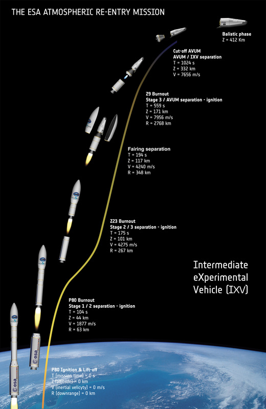 The first stage burns for 104 seconds and separates from the second stage immediately after pressure sensors detect the pressure drop in its combustion chamber signaling the burnout of the stage. P80 delivers the vehicle to an altitude of 44 Kilometers and a speed of 1,877m/s, parting ways with the second stage 63km downrange from Kourou. Immediately after the pyrotechnic stage separation system is triggered, the Z23 second stage ignites achieving a thrust of 121,960 Kilogram force to continue powered ascent by burning 23,906 Kilograms of propellant over the course of a 71-second burn. The 8.4-meter long stage burns out 175 seconds into the flight at an altitude of 101 Kilometers and a velocity of 4,275m/s, at a point 267 Kilometers downrange. Separation from the Z9 third stage occurs after a delay of a few seconds, at T+3:25.
At T+4 minutes and 2 seconds, Vega jettisons its protective payload fairing that is 7.9 meters in length and 2.6 meters in diameter offering just enough space for the rather large IXV spacecraft compared to the satellite payloads that usually ride atop the small launch vehicle.
The Z9 stage of the vehicle will ignite after a short coast to finish boosting the vehicle out of the atmosphere. It measures 4.2 meters in length and has a reduced diameter of 1.9 meters, burning 10,115 Kilograms of propellants over the course of a burn of 109-seconds. Z9 operates at a nominal thrust of 22,940 Kilogram-force.
With the fairing gone, IXV begins processing GPS data as part of its navigation system that also uses the IMU to integrate the non-gravitation acceleration to track the speed of the vehicle and evaluate its orientation in space. GPS data is used throughout the flight to update the inertial navigation solution with the position and velocity vector from GPS measurements. Guidance and Control modes of IXV remain in a passive setting for ascent since the launch vehicle is in charge of placing the vehicle into its targeted trajectory, requiring no inputs from IXV.
The Z9 stage burns out and remains attached to the vehicle until T+6 minutes and 37 seconds to allow residual thrust to tail off and ensure a clean separation through pyrotechnics and loaded springs.
The third stage delivers the vehicle to an altitude of 171km, a speed of 7,956m/s, separating at a downrange distance of 2,768km.
Once on its planned trajectory, the AVUM upper stage will assume control of the flight. AVUM, the Attitude and Vernier Upper Module, is 2.18 meters in diameter and 2 meters long holding a total of 550 Kilograms of Unsymmetrical Dimethylhydrazine and Nitrogen Tetroxide Propellants. The AVUM also houses the vehicle’s control system that is in charge of controlling all four stages of the launcher.
Ignition of the RD-869 engine of AVUM is set for T+8:00 on a burn of five minutes and 49 seconds that delivers IXV to its planned sub-orbital trajectory of 76 by 416 Kilometers at an inclination of 5.4 degrees. Separation from the AVUM is expected at T+17 minutes and 59 seconds at an altitude of 332 Kilometers and a speed of 7,656m/s.
AVUM continues its flight without IXV, conducting a second burn at T+31:14 lasting just 16 seconds to raise the perigee of the orbit to an altitude that does not endanger the vehicle of re-entering. A deorbit burn is performed by AVUM at T+1 hour 49 minutes and 31 seconds to target an appropriate location for entry, avoiding re-entry close to IXV that would have occurred in case no more maneuvers were performed after spacecraft separation. The deorbit burn has a planned duration of 59 seconds.
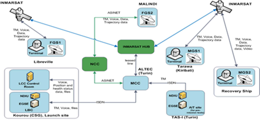
IXV Communication Paths
For IXV, the real journey begins at spacecraft separation, beginning with a ballistic segment that takes the vehicle halfway around the world before beginning its re-entry – the main event of the flight. The triggering of separation switches prompts the flight computer to switch to the Orbital GNC mode – continuing to use the IMU and GPS for navigation, enabling the Reaction Control System for attitude control and executing a guidance software that controls the vehicle in a way to maintain a pre-determined attitude profile to ensure proper communications with ground stations and GPS satellites.
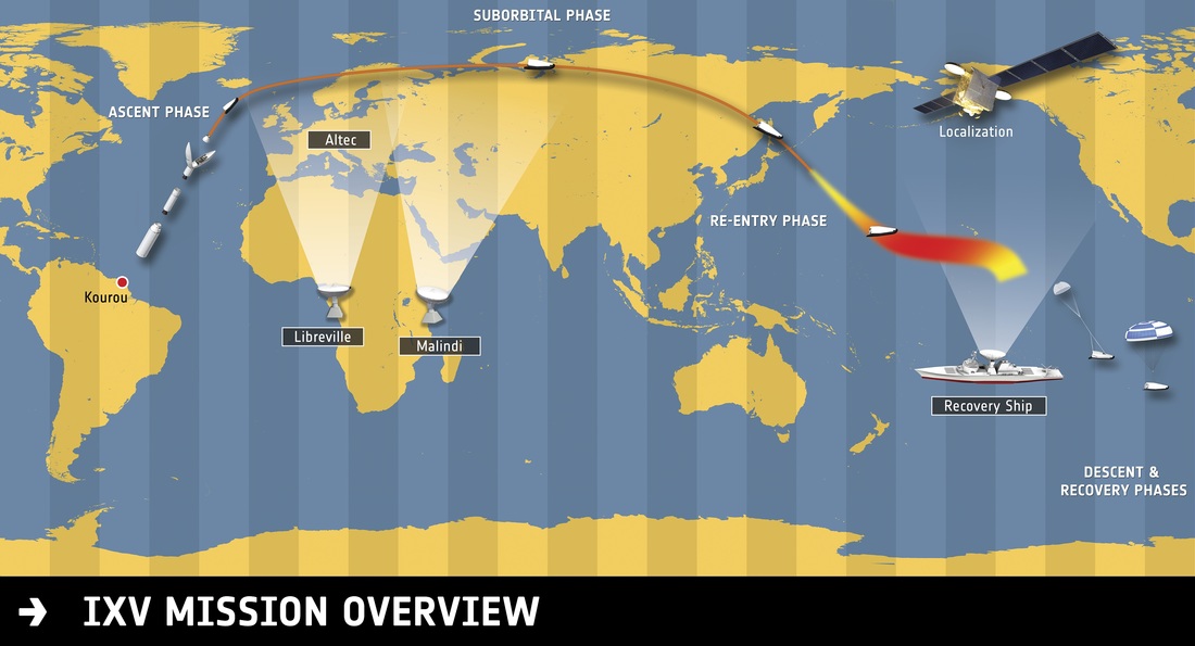
Set for nearly an entire lap around the planet, IXV requires a series of ground stations to receive and relay data from the spacecraft that consists of normal status telemetry to allow insight into the health of the spacecraft as well as experimental data from the 300 sensors installed on the craft.
Mission Control for IXV is located at the Advanced Logistics Technology Engineering Center, in Turin, Italy from where all elements of the mission are coordinated including the operation of the different ground stations, the distribution and storage of mission data and the coordination of the recovery effort carried out by the Nos Aries vessel in the Pacific Ocean, stationed at a safe standoff distance of 25 Kilometers to the planned landing location. To track the spacecraft on its journey around Earth in a nearly equatorial trajectory, the Libreville ground station in Gabon and the Malindi station in Kenya, both equipped with 10-meter dishes, will be in charge of receiving direct telemetry downlink from the vehicle and also receive the separate experimental layer data. The re-entry portion of the mission will be covered by the tracking equipment installed on the recovery ship – including the most crucial part of data downlink: the playback of stored sensor data collected during the re-entry blackout, the phase of the mission that is of great interest.
The Mission Control Center is also responsible for the calculation of the trajectory of IXV based on measured launch vehicle performance and tracking data collected immediately after spacecraft separation in order to update the recovery ship in the event an off-target landing is to be expected.
IXV is fully autonomous – there is no way of commanding the spacecraft. Entering its ballistic segment, IXV will perform attitude maneuvers with its four 400-Newton thrusters that keep the vehicle within a certain attitude corridor to ensure its transmitters are in a favorable position for visibility from the ground stations. The attitude is also driven by the requirement to ensure proper zenith-pointing of the GPS antenna which is done by having the craft follow a pre-determined attitude profile stored in the flight computer – consisting of desired attitude as a function of vehicle longitude. During the orbital phase, the GPS system is regularly used to provide position and velocity vector updates to re-initialize the inertial navigation resolution.
Mission Profile
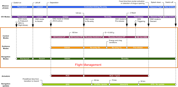
IXV GNC & Flight Management Modes
IXV is handed from Libreville to Malindi 23 minutes after liftoff and passes its apogee at 416 Kilometers in altitude at T+32 minutes into the mission. The comm coverage of Malindi ends at T+34 minutes and IXV will pass through a Loss of Signal until the recovery ship can acquire the spacecraft.
For the first part of its mission, IXV is in a Low Performance GNC mode that allows attitude errors up to 20° on the y and z-axis and 10° on the x-axis since high precision in vehicle attitude would only consume an unnecessary amount of propellant. The High-Performance Mode is initiated when passing 165 Kilometers in altitude and is more stringent from an attitude error standpoint as the orientation on all axes has to match up to within 5 degrees to the commanded attitude. Ahead of re-entry, a navigation update is performed through GPS to correct any errors such as IMU drift occurring over the course of the ballistic phase.
The Entry Interface point is set at 120 Kilometers, expected at T+64 minutes, and marks the point of the initiation of Entry Guidance that stabilizes and guides the vehicle to the target chute opening conditions while ensuring IXV sticks to the planned flight corridor. At Entry Interface, a Low Performance Entry Mode is initiated that only uses the Reaction Control System for vehicle control with the guidance system operating in an open-loop mode. Once the IMU senses a drag level of 0.05G, the GNC mode changes to the High Performance setting in which the two aerodynamic flaps are enabled and the flight control system begins sending commands in the form of opening times of the thruster valves and desired flap deflection settings. Closed-loop entry guidance starts when the GNC system senses a pre-programmed energy condition.
In this mode the GNC system is automatically commanding the vehicle attitude based on the sensed trajectory conditions in order to achieve the target conditions for the trigger of the parachutes. This GNC mode begins at a speed of Mach 25 at 80 Kilometers in altitude and continues down to Mach 2. Entry guidance modifies the downrange by adjusting the angle of attack to ensure the vehicle achieves its planned entry range while roll reversals are used to control the cross-range.
The flight control output is a vertical lift-to-drag ratio that is converted to a bank angle command that can be executed by the flap system.
Over the course of the 20-minute entry sequence, the IXV spacecraft will experience a maximum temperature of 1,700°C. Re-Entry blackout occurs when the plasma building up around the vehicle prevents any radio communications with the ground – all sensor data gathered during this period is stored and played back once the recovery ship has acquisition of signal – ensuring that the data is safe on the ground even if IXV can not be recovered after splashdown. Blackout is expected to end at T+82 minutes.
Once sensing a velocity of Mach 2, GNC enters a pre-release mode and commands the vehicle to an attitude condition that complies with the chute release at zero bank and sideslip angles and an angle of attack around 43°. The Parachute System is triggered at a velocity of Mach 1.4 to 1.6 at an altitude of 24.5 to 28 Kilometers. Post-release mode its triggered shortly after the command to deploy the pilot chute is sent and lasts through the deployment of the supersonic chute. When deployment of the supersonic chute is sensed, the GNC system enters descent mode – disabling the flaps and thrusters.
IXV first deploys a Disk Gap Band Pilot Parachute with a diameter of 1.7 meters designed to fully inflate within two seconds to pull the supersonic drogue chute out of its parachute bag. The 4.3-meter drogue parachute stabilizes the vehicle during the transonic transition, slowing the spacecraft down to Mach 0.3 at an altitude of ten Kilometers which is safe to deploy the main parachute, a 7.4 meter ribbon chute. During the second stage of its descent under the parachute, IXV transitions to a vertical descent, reaching an altitude of five Kilometers and a speed of Mach 0.12 when the third chute is deployed, measuring 29.6 meters in diameter.
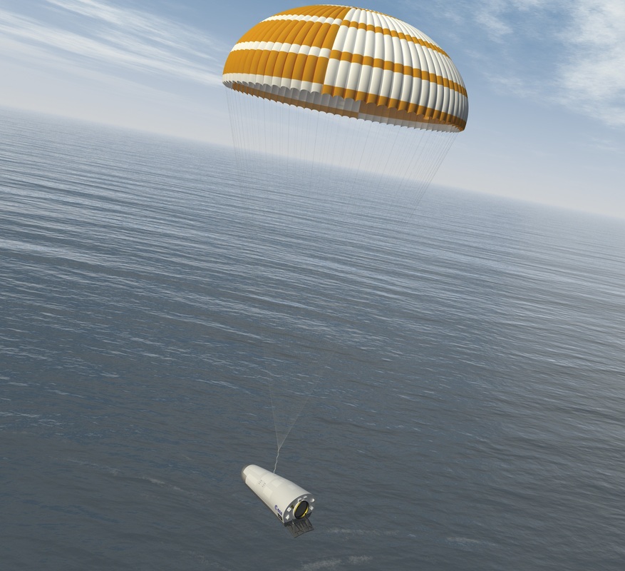
The final chute utilizes reefing stages to reduce the maximum force acting on the vehicle to 3.7 Gs. Initially, the chute will be flown at a 10% reefing stage for ten seconds before being fully inflated to slow the spacecraft down to 6 meters per second for splashdown at a target location of 3°N 123°W.
Splashdown is sensed by the Inertial Measurement Unit and triggers the inflation of the Flotation System that consists of four airbags that are capable of keeping IXV afloat for up to 48 hours which should be plenty of time for the recovery operation.
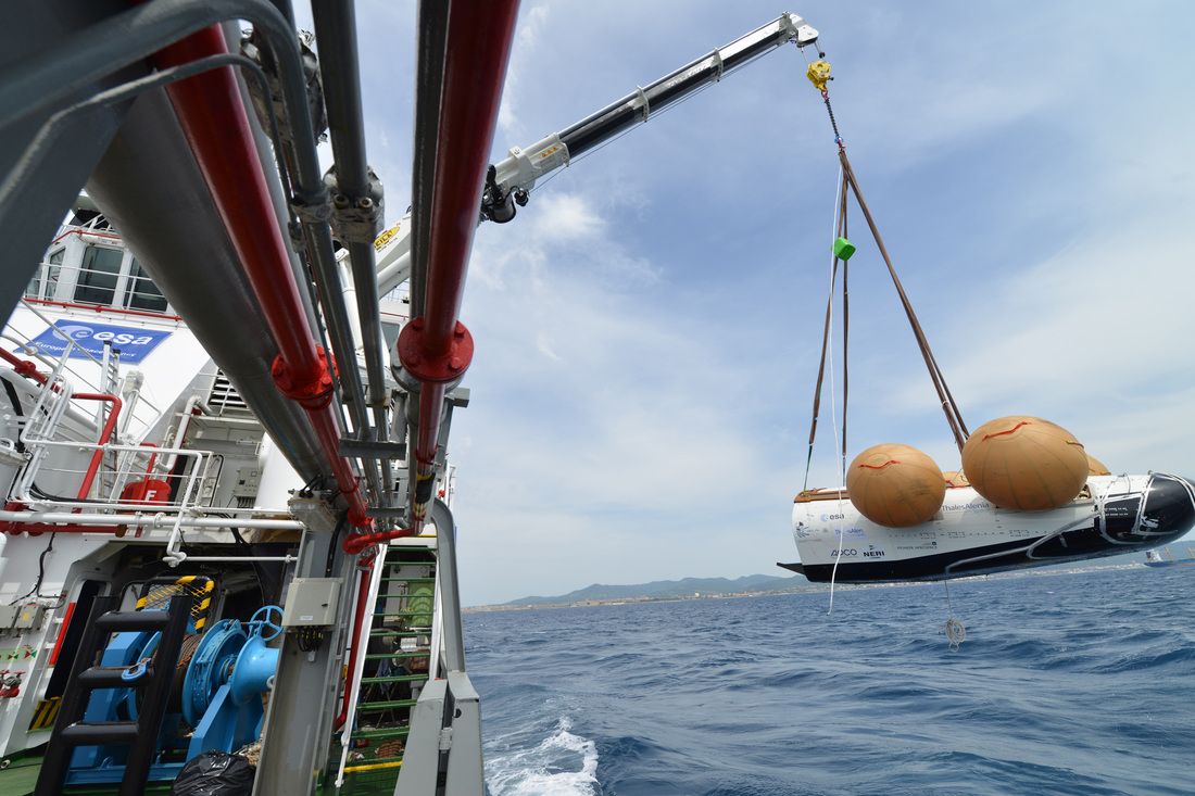
Once splashdown is confirmed, expected 102 minutes after launch, the Nos Aries will head toward the vehicle guided by beacon signals that start being sent by the spacecraft immediately after splashdown. Using a crane and a harness connected to IXV by divers, the vehicle will be retrieved from the Ocean for detailed post-flight inspections which will add valuable information to the sensor data and reveal how the various systems fared during re-entry.
Mission Timeline
Brief Project History
The IXV project dates back to 2004 when ESA’s Future Launcher Preparatory Program was initiated to define, among other technological demonstrator projects, the IXV re-entry system as a platform for the verification of in-flight performance of critical re-entry technologies. In the two years that followed, different IXV design proposals were downselected ending up at a final concept of a lifting-re-entry body designed to be launched and injected on a re-entry path by the Vega launcher using an equatorial trajectory taking the vehicle back to a landing in the Pacific Ocean.
In 2007, the project went through the System Requirements Review leading into Phase B of the program that was in progress in 2008 and 2009. The Preliminary Design Review was passed, however, the project was set back somewhat by a number of redesigns that were necessary due to changes in the industrial organization at the prime and subcontractor levels. The Critical Design Review and Equipment Qualification Reviews in 2011 paved the way for the next phase of the project – the manufacturing, assembly and testing of the complete spacecraft and ground support equipment for a launch in late 2014. IXV was delivered to the launch site in September 2014 to be loaded with propellants and installed on the Vega launcher for liftoff. Additional analysis of the launch trajectory required a delay of the mission into 2015 to clear any concerns with range safety.
