Hayabusa-2 – Asteroid Exploration Mission
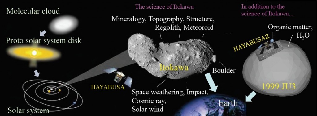
Hayabusa 2 is an Asteroid exploration mission by the Japanese Space Exploration Agency setting out to study Asteroid 1999 JU3, dispatch a series of landers and a penetrator, and acquire sample material for return to Earth. The mission builds on the original Hayabusa mission that launched in 2003 and successfully linked up with asteroid Itokawa in 2005 and returned samples to Earth in 2010 marking the first time sample materials from an asteroid were brought back to Earth.
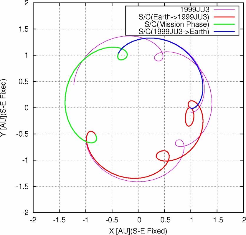
Hayabusa 2 is planned to complete a mission of six years – launching in December 2014 and traveling through the solar system for three and a half years, arriving at 1999 JU3 in July 2018 to spend 18 months studying the asteroid before making its return to Earth in December 2020.
The Hayabusa 2 spacecraft hosts two remote sensing spectrometers dedicated to studying the energy balance of the asteroid and its surface composition. The primary payload of Hayabusa 2 is a sample collection system that will acquire small amounts of surface samples during brief touchdowns of the main spacecraft on the asteroid’s surface using a high-fidelity navigation system that allows the spacecraft to make contact with the surface just long enough to shoot down a projectile that causes an ejection of dust for collection by Hayabusa.
Furthermore, the spacecraft will dispatch four landers – the 10-Kilogram MASCOT lander built in Europe for an in-situ study of surface composition and properties, and three MINERVA landers to deliver imagery and temperature measurements. All landers will make several hops across the asteroid’s surface to take measurements at different locations.
Another payload of the mission is an impactor device that will be deployed towards the asteroid and uses high-explosives to generate a high-speed impact that is hoped to expose material from under the asteroid’s surface for later collection by Hayabusa 2. A deployable camera will be used to document the impact of the penetrator.
After all these ambitious events at the asteroid, Hayabusa 2 will make its way back to Earth to send a Return Capsule on its way to re-enter the atmosphere and bring the collected samples back to Earth for analysis.
Hayabusa 1
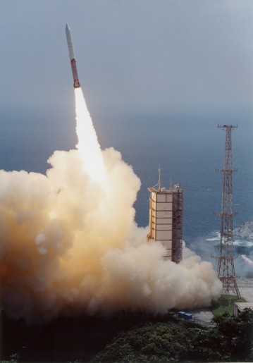
Launched on an M-V rocket on May 9, 2003, the 510-Kilogram Hayabusa craft embarked on a long flight to its target which had to be changed multiple times due to delays related to the M-V launch vehicle. One year after launch, Hayabusa swung past Earth to accelerate and make its way out to Itokawa in its 0.95 by 1.7 AU orbit around the sun.
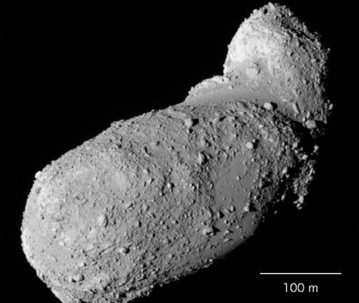
The craft officially arrived at its destination on September 12, 2005 when it reached a distance of 20 Kilometers to the asteroid. In subsequent weeks, the spacecraft descended to 7 and then to 3 Kilometers before beginning a descent to deliver a target marker to test out the vehicle’s tracking capabilities. This rehearsal landing was aborted due to problems with the optical navigation system and teams needed to re-group ahead of commanding the vehicle to once again descent from 7.5 Kilometers on November 2.
This second descent was a success and saw the spacecraft reaching 70 meters, verifying the navigation system and delivering a landing marker to validate the vehicle’s target tracking capability. With a landing site selected, the spacecraft approached to 55 meters by November 12 when the small MINERVA lander was released, but failed to reach the surface due to an error in its delivery. On November 19, Hayabusa landed on the asteroid, but teams on the ground were confused since the landing came during a handover of ground stations and by the time communications were regained, the vehicle had moved to 100 Kilometers from the asteroid.
It was later confirmed that the vehicle did make contact with the surface of the asteroid, however, a problem during descent put the craft into safe mode so that the sampling system was not activated at touchdown. Nevertheless, the landing was thought to have delivered some dust particles to the sample container that was subsequently sealed off. On November 25, Hayabusa made its second landing, but again failed to initiate its sampling sequence before having to go into safe mode due to a leak in the propellant system.
Over the next two weeks, teams were fighting to keep the mission alive since the spacecraft was loosing attitude control – its reaction wheels had already failed and the thruster leak caused the vehicle to spin – pointing its solar arrays away from the sun leading to power issues and pointing the communication antennas away from Earth. After attempts to correct the attitude by venting xenon gas through the ion thruster system, contact with the probe was lost on December 8 due to a sudden change in orientation. To stabilize, Hayabusa needed time for the conversion of precession rate to pure rotation which was expected to take several weeks.
Finally, on January 23, 2006, beacon signals from the spacecraft were received and three days later, command capability was restored, allowing teams to instruct the craft to make another xenon ejection which improved the orientation of the craft that re-acquired low-gain communications in late February. By March, medium-gain comm had been re-established and tracking showed the craft 13,000 Kilometers from Itokawa. With two out of four ion engines still up and running and 7 of 11 batteries still being recharged, the spacecraft started its return journey in April 2007.
To get back to Earth, the spacecraft completed two several-month long trajectory maneuvers in 2007 and 2009 into 2010. By March 2010, Hayabusa entered its final trajectory adjustment maneuvers to set up a proper re-entry path for the return capsule which required three trajectory corrections, each several days in duration. By June 5, the spacecraft had achieved a re-entry trajectory over the Woomera Prohibited Area in Australia – a broad strip of uninhabited land suitable for the parachute-assisted landing of the return capsule holding the sample containers.
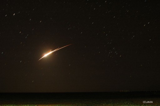
Three hours prior to entry, the capsule was released from the spacecraft, on a path to hit the atmosphere at 12.2 Kilometers per second. The return capsule made a successful landing while the main spacecraft burned up in the atmosphere. Several hours after landing, the return vehicle was located and recovered to be flown back to Japan to mark the start of the several-month process of opening the sealed sample containers and extracting any particles.
In November 2010, it was announced that about 1,500 particles of extraterrestrial material were found and in the process of being analyzed. It was determined that the composition of Itokawa was similar to that of rocky meteoroids found on Earth confirming its identity as S-type asteroid. Scientists also determined that the dust collected by the spacecraft was exposed to the space environment for about 8 million years, an extremely short time scale in astronomy. This indicated that Itokawa possibly broke apart from a parent asteroid.
Road to Hayabusa 2
With Hayabusa 1 still on its way through the solar system, a possible follow-on mission was proposed in 2006 to closely resemble the original mission featuring a nearly identical spacecraft with only minor changes to respond to issues seen during the Hayabusa mission. With the initial drive to fly the mission as soon as possible teams were hoping to launch in 2010 or 2011, but the budget did not permit a launch then. The additional development time allowed more changes to be made to the original spacecraft design to use more advanced and robust systems and modify the payload suite, also acquiring international support from NASA and a team of the German Aerospace Center and CNES. New systems were added including a Ka-Band antenna and impactor.
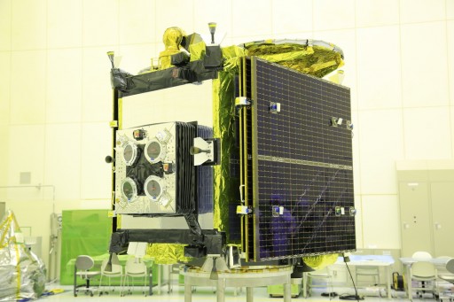
In 2012, the project transitioned from a proposal to a development stage when the Critical Design Review green-lighted the assembly of the spacecraft. Integration tests started in 2013 and the spacecraft was fully integrated by the end of that year, on the road to launch in late 2014.
Target Asteroid
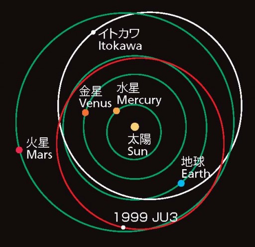
Asteroid 1999 JU3 was discovered by the Lincoln Near-Earth Asteroid Research (LINEAR) that has been heavily studied using ground and space-based telescopes. Telescopic data shows that the asteroid is about 920 meters in size and has a rotation period of 7.6 hours. Spectroscopic analysis showed that that asteroid belongs to the C-type class of primitive bodies. Data also suggests that the asteroid, at some point in its life, was in contact with water. JU3 orbits the sun in an orbit of 0.963 by 1.416 Astronomical units, inclined 5.88 degrees. This orbit, stretching from Earth’s orbit out to just outside the orbit of Mars with a small inclination makes the object suitable for a return mission.
Why Asteroids?
Asteroids, like comets, are of particular interest to scientists since they are primitive bodies that can be considered to be the building blocks of the early solar system and hold a record of the birth and initial evolution of the solar system. Larger planets like Earth went through a more complex evolution over which the pristine materials were melted and altered significantly. Due to this change, the materials found on large planets do not hold information into their early stages of formation.
Comets and asteroids, formed early in the evolution of the Solar System, retain a record of when, where and in what conditions they were formed. Exploration of these primitive bodies is essential in gaining insight into the formation of the Solar System. This may also provide clues into the presence and composition of organic molecules in the early solar system and possible mechanisms of their delivery to Earth. Learning about the formation of our own Solar System will also provide valuable information on exoplanets and their formation.
Asteroids can be divided into different classes based on their composition with each group showing different distributions within the asteroid belt between the orbit of Mars and Jupiter, depending on their distance to the sun. While Hayabusa studied and returned sample from an S-type asteroid that are stony in composition, the follow-on mission will explore a C-type asteroid.
S-type asteroids deliver information on the components of rocky planets such as Mars and Earth; they are also the origin of the LL Chondrite, the most common meteoroid found on Earth. The C-type asteroids are believed to hold a significant amount of organics or hydrated minerals and may have played a role in the delivery of organics to Earth. All this information is based on spectroscopic data from telescopic observations as well as analysis of meteoroids found on Earth.
Other asteroid types that can be found farther from the sun are P- and D-type asteroids that are not abundantly found on Earth due to their stable orbits in the outer region of the asteroid belt or as Jovian Trojans. It is desired that a possible Hayabusa 2 follow-on mission would study one of these types of bodies to get a full picture of the composition of the different primitive bodies.
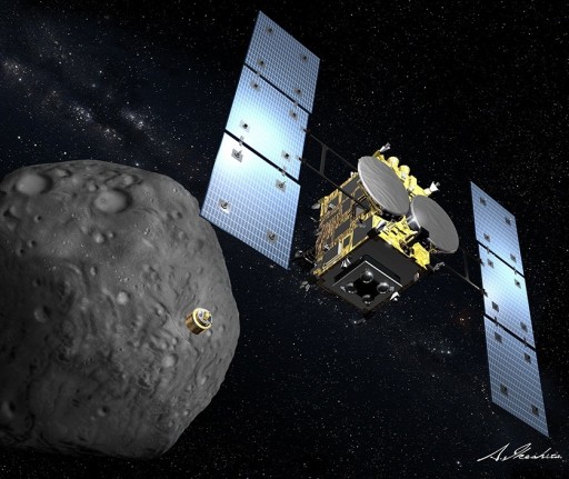
Hayabusa 2 Spacecraft
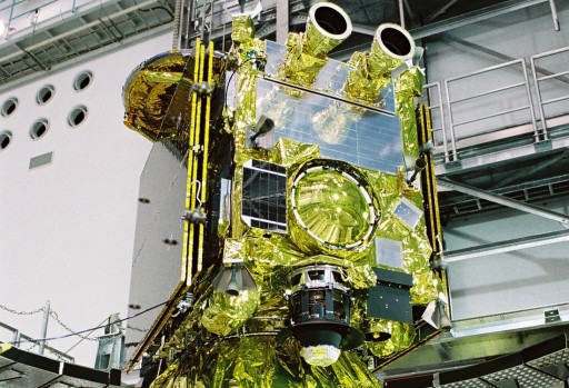
The Hayabusa 2 spacecraft is similar in architecture to the first Hayabusa spacecraft with a number of notable changes, not only to the instrument and payload suite, but also to the spacecraft platform itself. These changes include the addition of a reaction wheel to create a redundant configuration, the addition of a Ka-Band communications system and changes to the Ion Engine System using more robust technology. Components kept from the original mission allow teams to rely on flight-proven technology that has shown to perform well over the course of a mission lasting over half a decade.
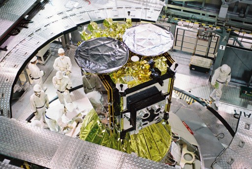
The Hayabusa 2 spacecraft consists of a spacecraft platform 1.6 by 1.0 by 1.2 meters in size using composite materials and aluminum alloy for a structural framework and internal and external panels providing mounting surfaces for the various spacecraft systems and payloads. The vehicle has a dry mass of 490 Kilograms and is capable of holding nearly 100 Kilograms of propellants. With its solar arrays deployed, Hayabusa 2 has a span of six meters.
Electrical & Thermal Systems

Power generation is provided by two deployable solar arrays, each consisting of three square panels suspended on two booms that interface with the center panel and the upper deck of the spacecraft platform. With a total surface area of 12 square meters, the arrays are expected to deliver 2,600 Watts of electrical power when the spacecraft is 1 Astronomical Unit from the sun, decreasing to about 1,400 Watts when the vehicle is at 1.4 AU, the aphelion distance of the asteroid. Power is stored in a 13.2 Amp-hour Lithium Ion Battery. Power is distributed to the various satellite systems using a 50-Volt power bus with power being distributed by Series Switching Regulators that provide battery control and bus protection.
The spacecraft includes a cold re-start feature. In the event of a loss of all power, the vehicle can automatically re-start once power generation resumes in order to protect for a loss on sun-pointing attitude or other unforeseen events that can lead to a spacecraft shutdown.
Spacecraft thermal control is accomplished using a combination of passive thermal control featuring blankets and multilayer insulation and active thermal control using thermally conductive coldplate assemblies, heat pipes and radiators installed on the cold side of the spacecraft. Heaters are used to maintain operating temperatures of electronics equipment when needed.
Attitude Determination & Control
Hayabusa 2 uses a number of Attitude Determination and Control Systems and a combination of electrical and chemical propulsion. Attitude Determination is provided by two star trackers, two Inertial Measurement Units, four accelerometers and four Coarse Sun Sensors. The Attitude and Orbit Control Unit serves as the brains of the various sensors and actuators – being capable of autonomously maintaining a pre-programmed distance to the asteroid using data from the navigation sensors that also include optical systems and it also controls all descent events to ensure a soft landing and successful ascent. The system uses an extended Kalman filter that outputs the position and relative velocity that are processed using an orbit dynamics tool and a basic gravity field model of the asteroid.
The primary attitude sensors are two star trackers which acquire imagery of the sky that is analyzed by a software algorithm that compares the acquired star pattern with a catalog to precisely determine the spacecraft’s orientation in space. Each star tracker has a field of view of around 8 x 8 degrees and uses a CCD detector operating at 1Hz.
Hayabusa 2 maintains its attitude through the use of four reaction wheels that allow control of the vehicle about all three axes. The reaction wheel assembly is a rotating inertial mass that is driven by a brushless DC motor that spins the wheel. When accelerating the wheel, the satellite body to which the wheels are directly attached will rotate to the opposite direction as a result of the introduced counter torque.

The original Hayabusa spacecraft had only three reaction wheels that were also capable of controlling the orientation on all axes, but did not have any redundancy. Early in the mission, one of the wheels failed followed by another later in the flight, requiring Hayabusa to rely on its engines to maintain its attitude. The addition of a fourth wheel ensures that the system can tolerate the failure of one of the wheels without losing any attitude control capabilities.
The four Coarse Sun Sensors are installed on different sides of the spacecraft and are capable of detecting the direction of the solar vector with some accuracy in order to be able to point the solar arrays to the sun in case of a spacecraft safe mode.
Two redundant Inertial Reference Units are used to augment attitude determination and for use to measure body rates in order to stabilize the spacecraft rates so that the star trackers can acquire star patterns which requires the spacecraft to dampen body rates to a certain level. The accelerometers provide insight into the operation of the propulsion system, allowing the precise tracking of the achieved changes in velocity supplied by the Ion Engine System that will be in operation for several thousand hours over the course of the six year mission.
Propulsion Systems
Like its predecessor, Hayabusa 2 combines a chemical and electrical propulsion system. The spacecraft hosts a bi-propellant chemical propulsion system using Monomethylhydrazine fuel and Nitrogen Tetroxide oxidizer, stored in propellant tanks that are pressurized with high-pressure gas to operate a total of 12 pressure-fed thrusters.
The 12 engines are operated as part of two strings that can be isolated in case of leaks or other problems. The ISAS-20N thrusters deliver a nominal thrust of 20 Newtons at a specific impulse of 290 seconds featuring a film-coating for thruster cooling.
The engines are capable of operating in pulse mode for spacecraft attitude control and in steady-state mode for Cruise Maneuvers and other translational burns. The thrusters also provide de-saturation of the reaction wheels – spinning the wheels down while countering the resulting force with the engines.
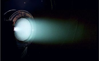
Hayabusa 2 will achieve the vast majority of the required change in velocity to travel to and from the asteroid by using its Ion Engine System – IES. Ion thrusters generate thrust by accelerating ions through the use of an electric field and ejecting these ions at extremely high velocity creating thrust force propelling the spacecraft forward. Although ion thrusters deliver a very low thrust, they are extremely efficient and consume only a very small amount of propellant. Through long operation of the thrusters, spacecraft can achieve changes in velocity of several Kilometers per second as demonstrated by Hayabusa 1 (over 2km/s), Deep Space 1 (4.3km/s), and Dawn (over 10km/s).
Ion thrusters use ions to create thrust in accordance with momentum conservation. The method of ion acceleration varies between the use of Coulomb and Lorentz force, but all designs take advantage of the charge/mass ratio of the ions to create very high velocities with very small potential differences which leads to a reduction of reaction mass that is required but also increases the amount of specific power compared to chemical propulsion.
The thrusters operate by releasing small amounts of Xenon atoms that are then ionized through electron bombardment by using electron cyclotron resonance microwave discharge – a new design that eliminated solid electrodes and associated heaters that were used as part of previous systems. The same microwave generator is used to feed the ion generator and neutralizer which reduces overall mass of the assembly. The neutralizer emits electrons near the exiting ion beam to ensure that equal amounts of positive and negative charge are expelled, thus preventing the spacecraft from gaining an excessive electrical charge that could damage components.
The generated ions are extracted by a dedicated system consisting of electrically charged carbon-carbon grids with primary acceleration of the ions taking place between the first and second acceleration grids. The negative voltage of the accelerator prevents ions from the beam plasma outside the thrusters from streaming back which would decrease the generated thrust. The ejected ions push the spacecraft in the opposite direction according to Newton’s third law.
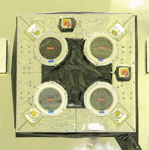
Hayabusa 2 uses four ion thrusters installed on a single panel of the spacecraft, facing the same direction to be able to combine thrust. Three units are in simultaneous operation, allowing the fourth system to come into play in the event one of the active thrusters fails.
The system is fed from a 51-liter xenon tank that can hold about 73 Kilograms of the gas. Each of the thrusters generates an operational thrust of nearly 10 mN at a specific impulse of 2,800 seconds. During operation, the system needs 250 to 1,200 Watts of electrical power. The entire Ion Thruster Assembly weighs about 70 Kilogram and the thrusters can be gimbaled by +/-5 degrees using an electromechanical system.
Improvements made to the propulsion system from Hayabusa 1 to 2 include a 25% increase in thrust and added mechanisms to prevent plasma ignition malfunctions in the ion source. The neutralizer, that had shown degradation after the first 10,000 hours of operation, was improved by protecting the outer walls from plasma and by strengthening the magnetic field to decrease the applied voltage needed for the emission of electrons. Hayabusa 2’s ion thrusters are planned to operate for over 18,000 hours.
Data Handling & Communications
The Hayabusa 2 spacecraft is controlled by a Central Data Handling Unit that interfaces with all spacecraft systems and is capable of auto-commanding spacecraft functions, execute commands sent from Earth, handle all payload and systems data, and deliver housekeeping and stored instrument data to the communications system of the spacecraft. The Data Handling Unit is based on a COSMO 16 Central Processing Unit and is connected to the Peripheral Interface Modules of the various spacecraft systems using a high-speed data bus. Collected data is stored in a 1GB data recorder.
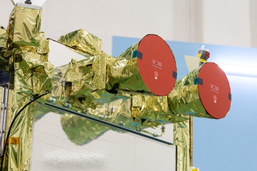
The communications subsystem of the Hayabusa 2 spacecraft is similar to that of Hayabusa 1 with the notable addition of a second High Gain Antenna as part of a Ka-Band communications system. Originally, Hayabusa flew with a large parabolic X-Band High Gain Antenna that took up most of the space on the upper deck of the spacecraft. Improvements in communication technology allows Hayabusa 2 to use two planar High Gain Antennas that are considerably smaller and have a lower mass while maintaining the same capabilities and communications characteristics.
Having two high gain communication systems adds redundancy and also expands the vehicle’s overall capabilities in terms of downlink volume. The X-Band system will be used for day-to-day operations, that is, telemetry downlink and command uplink to the spacecraft. The Ka-Band system is primarily used for the downlink of science data, taking advantage of its higher downlink rate of 32kbit/s. The Ka-Band system also allows for a more precise DDOR (Delta-Differential One-way Ranging) that will complement the normal line-of-sight ranging and doppler measurements for improved navigation during the mission.
The two High-Gain Antennas have a very narrow boresight, requiring the spacecraft to point to Earth to enable communications at up to 32kbit/s. A single two-axis gimbaled X-Band Medium Gain Antenna with an 18-degree cone is used for telemetry downlink and command uplink at lower data rates up to 256bit/s when the HGAs are not pointing to Earth. In case the HGA and MGA can not see Earth, Hayabusa 2 will rely on three omni-directional Low Gain Antennas that provide beacon signal and basic telemetry and command uplink capability at 8bit/s.
Optical Navigation Systems
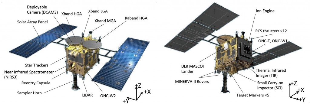
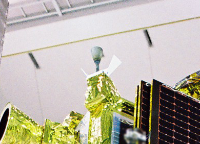
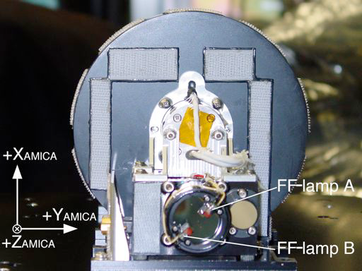
In addition to its absolute navigation instruments, Hayabusa 2 includes three Optical Navigation Cameras, a LIDAR, five Target Markers and a Flash Lamp to be used during proximity operations at the asteroid, the release of the landers and rover and the descent and touchdown of the main spacecraft.
The three Optical Navigation Cameras are known as ONC-W1 and W2 (Wide-angle cameras) and ONC-T (telescopic camera). The ONC-W1 and ONC-T cameras reside on the nadir-facing panel of the spacecraft, looking straight down at the surface, while the W2 camera is installed on the –x panel to provide a slant view.
All three cameras use two-dimensional CCD detectors, 1024 by 1024 pixels in size with pixel sizes of 12 micrometers. The detectors are sensitive in a wavelength range between 350 and 1,060 nanometers, covering the visible and near-infrared wavelengths. The cameras use a common electronics unit that employs a RISC processor and gate-array image processing technology providing image compression, center-finding, bright object detection, correlation tracking, terrain extraction and others needed for optical navigation.
The wide-angle cameras each have a field of view of 54 by 54 degrees achieving a resolution of 7 meters per pixel at a distance of 7 Kilometers to the asteroid. ONC-T has a narrow field of view of 5.8 by 5.7 degrees with a ground resolution of one meter from a distance of 7 Kilometers. The telescopic camera has a focal length of 121 millimeters and an aperture diameter of 15 millimeters.
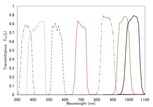
It includes a filter wheel containing a magnifying lens, six medium-band band filters with a bandpass of 15 nanometers at 390, 480, 550, 700, 860 and 950 nm, and a single sodium narrow band filter at 590nm with a 10nm bandpass. It takes 4.7 seconds to rotate the wheel from filter to filter. Using its different filters, ONC-T will be used for multi-band spectroscopy. ONC-T will support exposure times of 5.44 milliseconds to 178 seconds with an additional <1 microsecond exposure for streak elimination.
The cameras will be used during the cruise phase to acquire imagery of bright stars as well as the Earth Moon system for camera calibration.
Even at a large distance, the cameras will already be used to monitor the target asteroid for light curve and spectral observation and searching for a possible satellite of 1999 JU3. At the Home Point of 20km, the cameras are used for imaging the entire surface at a resolution of 2m/pixel using ONC-T that will also yield global spectroscopic observations.
In the low-altitude phase, observations will be performed from 5, 1 and 0.1 Kilometers for detailed surveying of local areas in order to find suitable landing sites and a good location for the deployment of the impactor. During lander deployments, the W2 camera will take images of the departing vehicle followed by W1 for descent and trajectory monitoring. After landing, the small vehicles will be located with ONC-T from one Kilometer in altitude.
During the descent for touchdown, the ONC cameras will be the primary navigation instrument from altitudes between 50 and 5 meters.
Imagery acquired by ONC will be used for morphological studies of the asteroid, the determination of asteroid volume for bulk density estimation, crater distribution to assess the age of the asteroid and to identify fresh soil locations, and studies of the artificially generated crater. Spectroscopic analysis involving ONC-T will provide information on the spectroscopic characteristics of the different surface features. This analysis will deliver data on basic composition of the surface, degree of hydration of surface materials and the presence of a sodium exosphere that could deliver data on the asteroid’s heating history which is considered an important piece of information by geologists.
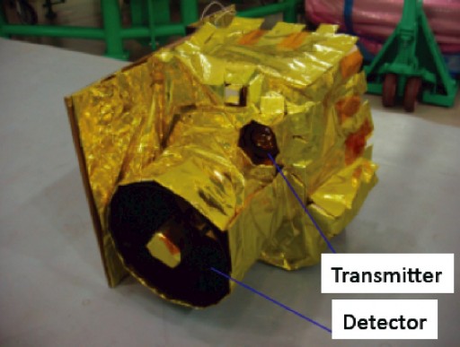
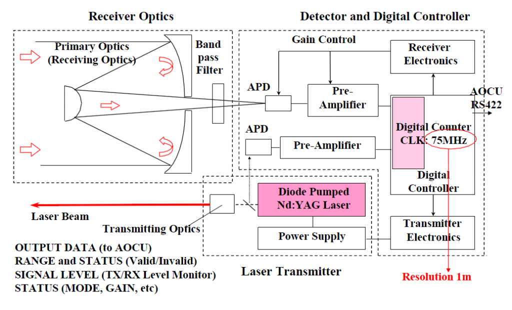
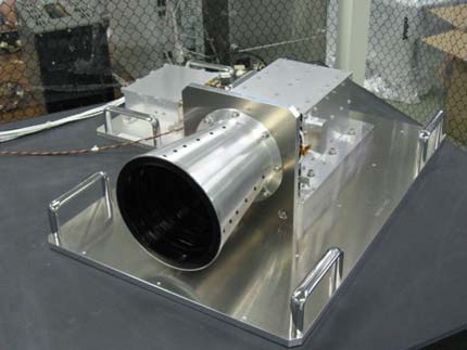
Hayabusa 2 is outfitted with a LIDAR unit that will be used for navigation when the craft is in proximity to the asteroid, scientific studies of the surface, and a technical demonstration for future optical communications systems. The LIDAR unit measures 24 by 24 by 23 centimeters in size and weighs 3.7 Kilograms comprised of a laser source and an optical head with telescope. LIDAR stands for Light Detection and Ranging and uses laser pulses that are reflected off a target to determine that target’s distance from the spacecraft.
The system pulses its 1,064nm infrared laser source at an energy of 10mJ per 10 nanosecond pulse, up to one pulse per second. The laser generates a beam with a divergence of 1.7 mrad, creating a footprint on the surface of about 20 meters from the 20-Kilometer home point. The laser light that is reflected by the asteroid is detected by using a Cassegrain telescope with a primary concave mirror and a secondary convex mirror aligned about the optical axis. The aperture of the telescope is 127 millimeters in diameter and the optics focus the light into a silicon-avalanche photodiode through a narrow-band filter only allowing the desired wavelength to reach the detector. All optical components are installed on a stable optical bench.
The LIDAR system will operate at a time resolution better than 3.3 nanoseconds allowing the system to determine the vehicle’s range with an accuracy of +/-5 meters from an altitude of 25 Kilometers, although it is expected that the system will acquire 1999 JU3 from a distance of 50 Kilometers. LIDAR data is provided to the spacecraft computer and the Attitude and Propulsion System to allow the spacecraft to autonomously maintain its planned altitude. When reaching 30 meters, a second set of optics will be employed for measurements up to +/-1 meter accuracy.
In addition to delivering valuable navigation data, the LIDAR will record the integrated intensity of each pulse as well as the associated received energy which will yield accurate measurements of surface albedo including that of shadowed areas. Furthermore, the system will provide topographical data.
In a Dust-Count Mode, LIDAR will detect the intensity of scattered light caused by dust in the vicinity of the asteroid. The instrument can not detect the abundance of dust particles, but will show the presence of dust over a certain threshold.
To serve as a demonstrator for future deep-space optical communications, LIDAR will be used around the time of the Earth flyby one year into the mission when a laser pulse will be sent from Earth to be received by LIDAR that will immediately return a pulse to the ground station to demonstrate a basic link experiment. The ground station to be used is NICT Koganei, using a 1.2J laser operating at a pulse repetition rate of 10 Hz.
Hayabusa’s Laser Range Finder comes into play late in the descent phase, consisting of four laser sources canted 30 degrees. It is activated at around 35 meters in altitude to deliver four oblique range measurements that are used by the attitude control system to keep the spacecraft pointed to the local vertical – ensuring that the bottom panel remains aligned with the local surface during the final meters of descent that are driven by the asteroid’s weak gravitational force. A fifth laser range finder is pointed at the sampling horn for the detection of contact signaled by motion of the sampling horn.
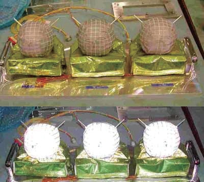
Hayabusa carries a series of five Target Markers that are released towards a landing site to provide a tracking target for the vehicle’s navigation instruments. These spherical, bean-bag type target markers are installed on the underside of the spacecraft to be released at an altitude of about 40 meters when the craft is approaching its landing site.
After releasing the marker, the spacecraft slows down to allow the marker to fall away from it and make contact well before the spacecraft. Once at an altitude of 17 meters, the spacecraft reduces its velocity to zero and enters a free-falling descent. At that point, the target marker is already on the surface and ready to be used for navigation.
During final descent, the Optical Navigation Cameras W1 & T1 on the nadir-facing panel operate a Flash Light that is activated every two seconds and imagery is acquired with the light on and off to allow the onboard software to subtract the two images from one another to determine the position of the target marker. This technique is used to identify any horizontal velocity that has to be eliminated by the spacecraft in order to achieve a safe landing, otherwise an abort would occur. Another optical navigation method is tracking of bright pixel groups to estimate horizontal velocity.
A final optical part of the landing navigation system are four Fan Beam Sensors that are installed on the solar panels of the spacecraft. Each side features one transmitter and receiver that create a three-dimensional detection area under the solar panels to detect any obstacles that could endanger the spacecraft during landing which would trigger an automated abort.
Sampling System
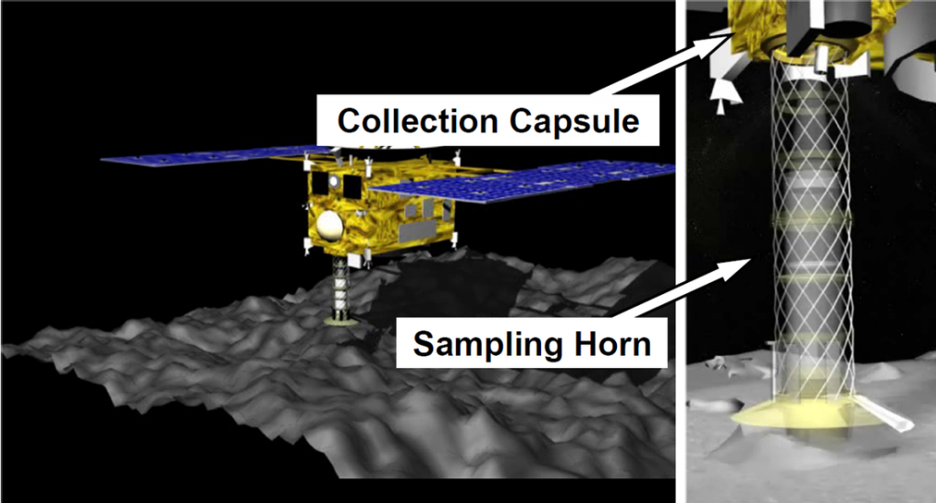
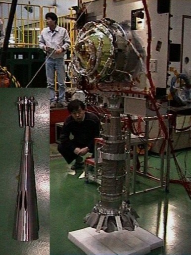
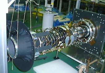
The Impact Sampling System of the Hayabusa 2 mission is almost identical to that of its predecessor – firing a projectile into the asteroid that ejects small grains of material which are caught in a sampling horn and travel up the sample collection system to be sealed in containers that will eventually be returned to Earth. The sampling system from bottom to top consists of a metal aluminum skirt, an extendable fabric horn, a conical horn funneling the sample into the spacecraft to the sample catchers and the sample container inside the Return Capsule.
The Sampling Horn extends about one meter from the nadir panel of the spacecraft and is cylindrical in shape with an inner diameter of 20 centimeters. At the bottom of the horn is an aluminum segment that makes contact with the asteroid and its motion, detected by a laser range finder, generates the touchdown signal. Attached to the skirt is a compressible fabric horn that, upon contact, will be compressed as a result of the downward velocity of the spacecraft.
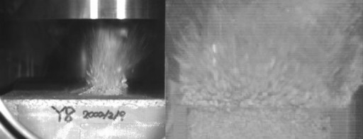
Upon reception of the touchdown signal, the automatic sample acquisition sequence is triggered. A 10-millimeter Tantalum projectile with a mass of 5 grams will be fired using a powder cartridge to impact the surface inside the sampling horn with a speed of 300 meters per second. Tantalum has been chosen as projectile material since it is a rare material and any contamination of sampling material with Ta can be easily attributed to the projectile. The power cartridge and a sabot are used to contain the residual gas when the projectile is fired.
The impact of the projectile ejects grains of surface materials that will continue moving upward due to the low gravity at the asteroid that is just about 1/100,000th of Earth’s gravity. Grains will float up, being directed through a conical horn and a 90-degree turn to allow the particles to come to rest inside one of three sample catchers in the Return Capsule.
Just one second after the firing of the projectile, the Hayabusa spacecraft fires its bi-propellant thrusters facing the –z direction to provide an upward force to begin the ascent from the surface. The time spent in contact with the surface has to be minimal since the spacecraft will continue free falling and will eventually risk falling on its side if it remains on the asteroid for too long.
After Hayabusa 1 failed to fire its projectile for both of its landings, the Hayabusa 2 spacecraft includes a backup sampling system. The aft skirt of the Sampling Horn was folded back inward like the teeth of a comb which will allow some material to be lifted up after the initial contact with the surface. This way, particles between 1 and 5 millimeters in diameter will be retained in the aft of the horn during ascent. If the spacecraft then decelerates, these particles will continue moving upward due to inertia, allowing them to enter the sample catcher.
The Hayabusa 2 spacecraft is equipped with three sample catches that reside within the Sample Container of the Return Capsule. After all three samples have been acquired, the sample container will be sealed using an aluminum metal seal – switching from a double O-ring design to the metal seal allows volatiles to be returned to Earth without escaping from the container. The overall Sample Catcher and Sample Container design was changed to allow an easier sample extraction for analysis.
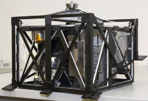
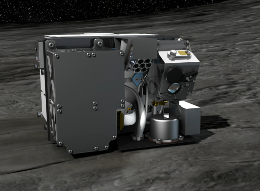
Small Carry-On Impactor – SCI
A new payload developed for Hayabusa is the Small Carry-On Impactor and the DCAM3 Deployable Camera. The overall mass of the system is 18 Kilograms including the various support systems, leaving 2 Kilograms for the actual impactor that will be accelerated to 2 Kilometers per second for the impact using a detonator. Due to the large size of the impactor and the use of explosives, the impactor is released by the spacecraft that will make its way to the opposite side of the asteroid to use it as a shield. Imaging of the impact will be completed by the small Deployable Camera DCAM3, based on the IKAROS remote camera.
The impactor itself consists of a copper liner – about 30 centimeters in diameter, a metal case, an igniter and the explosive detonator. The 2.5-Kilogram copper liner is in the shape of a shallow dish and as part of the EFP principle of the impactor (Explosively Formed Penetrator), the explosion will deform the liner into a slug shape and accelerate it to over 2km/s for impact. A total of 4.5 Kilograms of the HMX high explosive will be needed to accomplish the impact. HMX has an explosive velocity of 9km/s. The deformation and acceleration period is under one millisecond in duration, allowing the acceleration distance to be small and eliminating concerns of attitude disturbances changing the flight path of the projectile.
SCI resides on the nadir panel of the spacecraft and its release mechanism will supply a spin to the vehicle to stabilize it during free flight until ignition. The small vehicle includes a battery, an onboard sequencer, a safe and arm device and an igniter that is triggered based on time-tagged commands that use the separation time from the mothership as reference – a separation monitor generates the separation signal. Electrical and data connections to the Hayabusa spacecraft are part of a simple wire interface that facilitates a wire cutter on the spacecraft side to severe the cables prior to separation. Ignition of the detonator occurs roughly 40 minutes after separation.
The crater created by the impactor will be about four meters in diameter and expose material from the sub-surface that was not subjected to the space radiation environment and extreme heating. This material is of great interest to scientists and will be the focus of Hayabusa’s third landing attempt to collect samples of the material.
DCAM3 – Deployable Camera
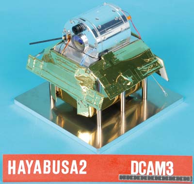
DCAM3 is a small deployable camera that is released from Hayabusa 2 in order to collect imagery of the impact of SCI on the asteroid and subsequent photographing of the spreading ejecta that will reveal information on physical properties of the surface of the asteroid. The DCAM3 instrument is cylindrical in shape with a diameter of about 6 centimeters using a metal casing. The lens tube is about 30mm in diameter and 40mm long.
The camera uses a wide-angle, high-resolution design and a one-way radio system to deliver acquired imagery to the Hayabusa 2 spacecraft. DCAM3 features a CMOS detector that is 1092 by 1092 pixels in size, generating 8-bit monochromatic imagery.
The camera has a field of view of 74 by 74 degrees and operates at up to one frame per second covering a spectral range of 450 to 750 nanometers. The CMOS detector is calibrated to acquire imagery with a high space resolution and brightness resolution to complete its imaging operation of the impact and the ejecta. At a nominal distance to the asteroid of around 1 Kilometer, DCAM3 achieves a resolution of 0.65 meters per pixel.
DCAM3 will be spin stabilized at 60 to 120 degrees per second to be able to point to the proper imaging area.
The batteries of the camera will last for several hours and may show the ejecta cloud reaching up to the camera’s altitude. While in operation, the camera will deliver acquired imagery to the Hayabusa spacecraft’s dual antenna system via a one-way communications link achieving high data rates of up to 4 Mbps. The overall volume of generated imagery will be on the order of a Gbit, to be stored aboard the spacecraft for downlink to Earth.
NIRS-3 – 3µm Near InfraRed Spectrometer
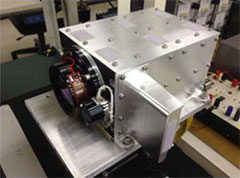
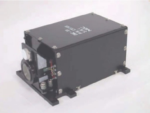
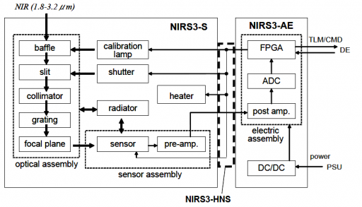
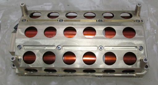
NIRS3 is one of two infrared spectrometer instruments. It is comprised of a grating infrared spectrometer, a spectrometer electronics unit and a cable harness that connects the two. A telemetry and command interface connects NIRS3 to the Digital Electric Instruments. Power is provided from the Power Supply Unit of the Hayabusa 2 platform. The instrument is installed on the –Y panel of the spacecraft, inside the spacecraft body with its viewing direction to the –z axis, looking directly down at the asteroid’s surface. Overall, the instrument is 35 by 17 by 10 centimeters in size with a mass of 2 Kilograms. The spectrometer covers wavelengths from 1.8 to 3.2 micrometers.
The optical system of the NIRS3 instrument consists of an aperture cover, a field stopslit, two mirrors, a diffraction grating, camera lenses, a detector and two calibration targets. The Al/Ge optical components reside on a stable optical bench protected by a carbon-fiber reinforced plastic box case. Infrared light entering the spectrometer through the 70 by 70-micron slit is dispersed by a flat transmission diffraction grating combined with a cross disperser. The mirrors then direct the dispersed light to the optics that re-focus the first-order light onto the detector. The spectrometer has a field of view of 0.1 by 0.1 degrees..
The detector of the instrument consists of a 128-pixel indium-arsenide photodiode array making up the linear image sensors of the instrument to achieve a high sensitivity in the 2 to 3 micrometer band. Each pixel is 50 by 100 micrometers in size. The spectrometer achieves a spectral resolution of 18 nanometers per pixel. A passive cooler connected to an external radiator is used to keep the optical assembly and the detector below –80 degrees Celsius.
The cross disperser is employed to prevent any other light than first-order from entering the detector. From its Home Point at 20 Kilometers, Hayabusa’s NIRS3 instrument can achieve a spatial resolution of 35 by 35 meters.
The NIRS3 instrument is controlled by a Field Programmable Gate Array that actuates all calibration lamps, the shutter, the heater and the focal plane assembly of the spectrometer. The integration time for each frame is programmed between 10 microseconds and 10 milliseconds. Shutter speeds up to 100 per second are possible. Data from the sensors is pre-amplified in the sensor unit before being transferred to the spectrometer electronics where post-amplification takes place ahead of analog-to-digital conversion.
Calibration of the instrument is accomplished by closing the aperture cover for the measurement of dark currents, and using a well characterized calibration lamp with a stable spectral maximum within the spectral range of the instrument.
The NIRS3 instrument has different operational modes. In its Normal Operation Mode, the instrument alternates between light and dark frames achieved by the closing and opening motion of the shutter that allows the dark current level of the detector to be subtracted from the light frame on a channel-to-channel basis every time an image is taken.
The primary scientific objective of the NIRS3 instrument is the observation of hydrated minerals that have been found in ground-based observation of the asteroid. Furthermore, the instrument will reveal locations of younger terrain and study the ejecta of the artificially created crater by SCI. The instrument can provide data for the estimation of the abundance of hydrated minerals with an accuracy of 1 weight-percent.
It is hoped that NIRS3 can reveal the initial composition, aqueous alternation, thermal metamorphism and space weathering on the surface of a C-type asteroid.
TIR – Thermal Infrared Imager
The Thermal Infrared Imager of the Hayabusa 2 spacecraft will deliver valuable information on the physical properties of the asteroid’s surface by monitoring regional variations of thermal inertia, thermal emissions, and temporal variations of surface temperature.
The TIR instrument uses a non-cooled bolometer array as a detector covering a wavelength range of 8 to 12 micrometers. TIR weighs 3.3 Kilograms and consists of an optical head, a detector unit and an electronics box. The optical head is comprised of a entrance baffle, all optics and the mechanical shutter while the electronics box consists of a pre-amplifier circuit, amplifier and analog to digital converter as well as the power and data interface to the Data Unit.
The Bolometer Array Instrument is an uncooled infrared imager that does not rely on a cryocooler to keep the detector cooled. The array consists of 320 by 240 pixels. Each pixel on the array consists of several layers including an infrared absorbing material and a reflector underneath it that directs IR radiation that passes through the absorber back to the absorbing layer to ensure a near complete absorption. As IR radiation strikes the detector, the absorbing material is heated and changes its electrical resistance which can be measured via electrodes connected to each microbolometer and processed into an intensity read-out.
TIR has a field of view of 16 by 12 degrees and covers a temperature range of 250 to 400 Kelvin, operating at a resolution of 0.5 degrees and a absolute accuracy of better than 5K. The instrument uses a 12-bit analog to digital conversion creating a data volume per image of 0.15MB. Calibration of the instrument is achieved by closing the shutter for dark current measurements.
TIR will investigate the nature and the formation processes of the asteroid, the physical properties of boulders and materials that are hidden inside craters.
This data will be used to determine whether the asteroid consists of a rubble-pile or primordial structure. Sedimentation in a microgravity environment will be studied by making observations of flat terrain.
TIR measurements can be used to validate the models of thermal inertia of asteroids and thermal conductivity against asteroid diameter. Data from TIR is going to be used in the selection of the sampling sites by providing data on the magnitude of the thermal alteration each location went through. Safety analysis in thermal wavelength is also considered in the selection of landing sites.
During the mission, TIR operates for one 7.6-hour asteroid rotation per week while more operating time will be available for global mapping at high phase angles. Smaller sites such as boulders and craters are identified during the mapping of the asteroid and will be observed by TIR when favorable passes occur. The instrument is active during the descent and touchdown phase for close-up and in-situ observations.
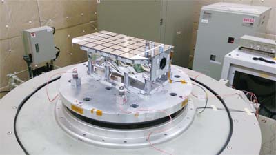
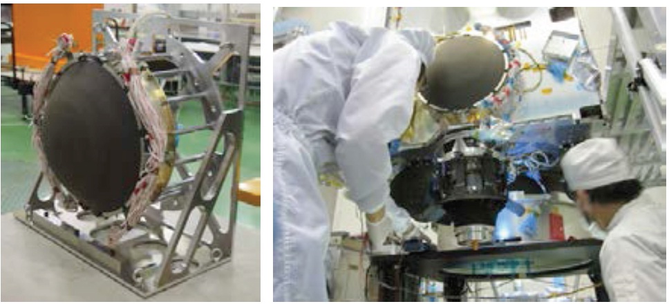
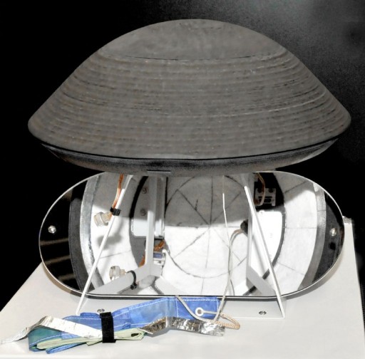
Sample Return Capsule
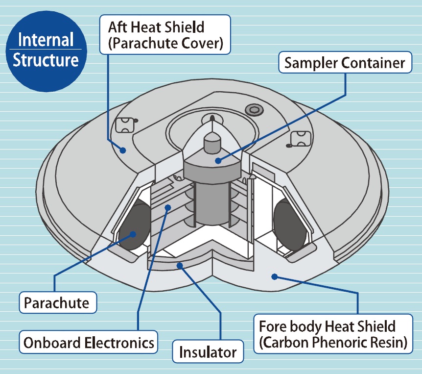
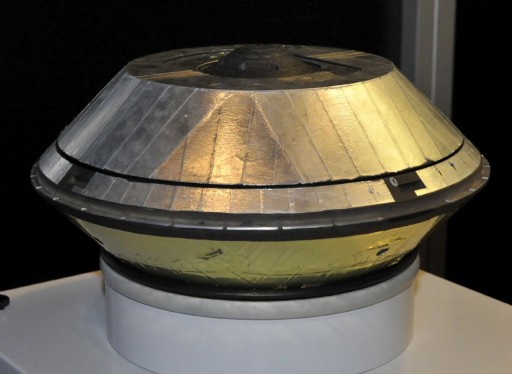
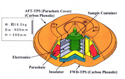
The Return Capsule of Hayabusa 2 is similar to that flown on the first mission, capable of returning the Sample Container with three filled sample catchers to Earth, performing a re-entry at a speed of 12km/s for a parachute-assisted landing in the Woomera Test Range in Australia. The Return Capsule has a total mass of 16.5 Kilograms, measures 40 centimeters in diameter and stands 20 centimeters tall.
In the center of the Return Capsule resides the Sample Container that is sealed after sampling operations are complete using an aluminum metal seal. Arranged radially around the Sample Container are the electronics of the entry vehicle including a new instrument called the REMM (Reentry Flight Measurement Module).
Outside the electronics compartment is the parachute segment that is surrounded by an insulator material that protects the internal systems from heating. The Return Capsule uses a carbon-phenolic ablator heat shield that is divided into the forward Thermal Protection System and the Aft TPS that functions as parachute cover.
The Return Capsule features a mechanical and electrical interface with the HY-2 spacecraft to permit the transfer of the samples as well as the exchange of data and commands and power supply from the spacecraft to the Return Vehicle to operate its heaters throughout the flight. The mechanical coupling is separated by a Merman Clamp Band that releases the Return Vehicle from HY-2 at the proper velocity and with a spin rate by using a helical coil spring. The Return Capsule is spin-stabilized, not employing active attitude control and relying on the spacecraft to release the vehicle onto the correct path in a good orientation for atmospheric entry that is completed in a ballistic mode.
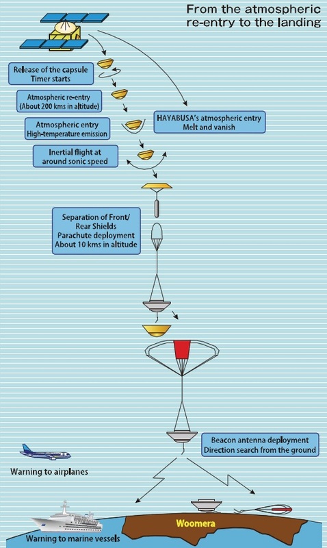
The separation of the Return Capsule takes place eight hours prior to re-entry to allow sufficient time for the Hayabusa spacecraft to perform a course correction to avoid entry and continue its flight in a heliocentric orbit.

The Return Capsule of HY-2 is projected to enter the atmosphere at a velocity of around 11.8km/s at a re-entry angle of 12 degrees which ensures a good capture in the atmosphere without the possibility of a skip-out, but also creates a steep entry with high thermal loads.
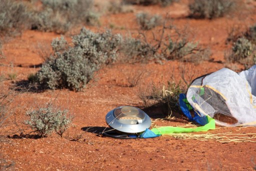
The Return Vehicle uses an ablative heat shield that consists of a carbon phenolic resin and slowly burns away during entry creating a boundary layer that separates the hot shock layer from the heat shield and reduces radiative heating by introducing carbon into the boundary, making it optically opaque. After re-entry, the forward and aft heat shields are jettisoned to prevent soakback from the ablator. Both of these segments fall back to Earth – the aft heatshield pulls the parachute bag away from the vehicle while the forward heatshield pulls the parachute anchors, allowing the chute deployment at an altitude of around ten Kilometers.
Under the high-strength parachute, the capsule transitions to a vertical descent and slows down for landing. A cross-type parachute is used by the vehicle. The instrument module exposes a beacon antenna on its way down, starting to transmit beacon signals to be received by recovery forces to locate the vehicle for safing and retrieval. The beacon continues operating after landing as long as the battery of the instrument compartment lasts.
REMM, the Reentry Flight Measurement Module, is a small instrument dedicated to measuring the dynamics of the re-entry of the spacecraft to deliver valuable data on high-energy entry dynamics for the improvement of future re-entry vehicles. The re-entry of HY-2 will also be observed from ground-based assets and potentially an airborne campaign to gather additional data. The REMM instrument consists of a three-axis accelerometer unit, a rate sensor unit and 13 temperature probes placed in various positions inside the vehicle. The accelerometer operates at a sample rate of 125Hz and can measure accelerations up to 50Gs. The rate sensor is capable of tracking even fast body rates of up to 200 degrees per second in any direction, also operating at 125 Hz. Operating at one measurement per second, the thermal monitor includes nine sensors in the capsule while four sensors are used within REMM itself, capable of operating at temperatures of –50 to 600°C with an accuracy of +/-3°C.
The system operates for seven minutes throughout the atmospheric re-entry phase, storing collected data in two 8-Mbit flash memories. The REMM instrument uses a battery cell that is independent of the main power source of the Return Capsule. The only interface with the Return Capsule system is in a data line that delivers the measurement start signal when re-entry begins, triggering the activation of the REMM instruments.
Landers & Rovers
The Hayabusa 2 mission includes a series of landing craft that are hitching a ride to the asteroid aboard the spacecraft, namely a series of three MINERVA II rovers developed at Japanese Universities and JAXA, and the MASCOT lander, a contribution from the German Aerospace Center and the French Space Agency CNES.
MASCOT
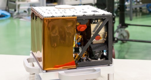
MASCOT – the Mobile Asteroid Surface Scout is a small lander developed by the German Aerospace Center and the French Space Agency using knowledge gained from the development of the Philae lander of the Rosetta mission that became the first craft to make a soft landing on a comet in November 2014. Initial studies of the lander began in 2008 and its realization was decided by JAXA, DLR and CNES in 2012.
The purpose of the MASCOT lander are to deliver context science data to complement remote sensing data acquired by the Hayabusa 2 instruments. Ground-truth information provided by MASCOT will be looking at the asteroid at a microscopic scale to deliver a unique set of data.
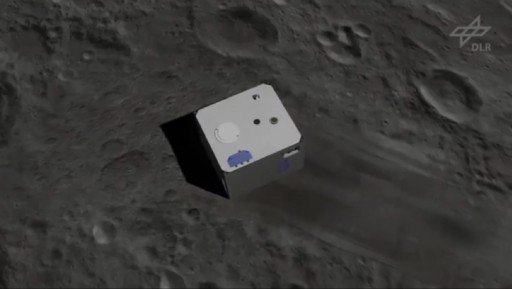
The MASCOT lander is designed to be able to hop from one location to another using a mobility system that will allow it to collect data from several locations while its battery lasts which is expected to be around 12 to 16 hours. The lander measures 0.3 by 0.3 by 0.2 meters in size with a mass of 10 Kilograms containing a number of subsystems including four instruments – a wide-angle camera, an imaging infrared spectrometer, a radiometer payload, and a magnetometer. Data from the instruments will significantly enhance the overall science return from the Hayabusa 2 mission, providing extensive in-situ data from the surface of an asteroid. The science payload has a mass of around 3 Kilograms.

The lander consists of carbon-fiber panels with a middle wall segment that carries loads occurring on impact and during hops across the surface.
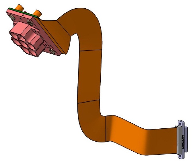
The middle wall is located between the payloads and a stack containing the main electronics box and the battery of the lander. The entire structural subsystem of the lander weighs just 450 grams. A Mechanical and Electronics Support Structure connects the MASCOT lander to the Hayabusa spacecraft that supports it throughout its journey to the asteroid by powering heaters aboard the lander and separating the vehicle from the mothership on a predictable trajectory for an on-target landing.
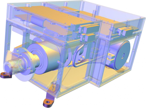
With a mass of not even half a gram in the gravitational field of the asteroid, the lander can easily withstand its initial contact with the surface and several bounces that are expected upon landing. It also means that only small forces are needed to move the lander from point to point. MASCOT’s Mobility System essentially consists of an off-centered mass installed on an eccentric arm that moves that mass to generate momentum that is sufficient to either rotate the lander to face the surface with its instruments or initiate a hop of up to 70 meters to get to the next sampling site.
The Mobility Mechanism is installed next to the middle wall of the lander, between the E-box/battery and the payload suite. All mechanical components of the system consist of aluminum alloy while the eccentric mass suspended on the arm is made from a high-density alloy.
The arm is driven by a 25-millimeter diameter high-density brushless DC motor that is connected to the arm through a harmonic drive gearing with a 1:30 reduction. Ball bearings used in the system feature a dicronite coating. The motor includes hall sensors and a relative position sensor provides the exact position of the arm to the MobCon electronics system that controls all functions of the Mobility System and executes commands from the lander controller.
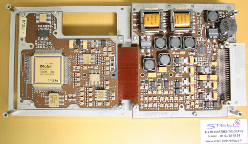
The entire electronics system is redundant in architecture, connecting the MobCon system to the Mobility Actuators and sensors on two fully independent paths that employ a full decoupling. MobCon is centered around an Actel Field Programmable Gate Array central processing unit that uses flash-based technology. The FPGA is connected to the Onboard Computer’s RS-422 data bus through a data line driver. An analog to digital converter is used to convert voltage, current and temperature measurements to digital values for processing by the FPGA and the generation of systems telemetry sent to the OBC. An BLDC Motor Controller is connected to a 3-Phase MOSFET bridge that drives the DC motor. Feedback is provided by the motor’s hall sensors and the relative position sensor. The FPGA runs the control algorithm for the position and control loop of the motor to generate actuation based on the commanded maneuver – hop or uprighting maneuver.
MASCOT is powered by a primary battery that can keep the lander in an operational state for 12 to 16 hours (depending on temperature). Provided by SAFT, based in France, the battery is a lithium thionyl chloride battery known as LSH20 that has excellent weight and volume characteristics. It consists of three parallel strings, each with three LSH20 cells. The battery has a capacity of 39 Amp-hours, generating an unregulated 11-Volt power bus. MASCOT power is handled by a Power Control and Distribution Unit that delivers power to all systems of the small lander. During the coast phase, the lander is powered by Hayabusa via a regulated power line. The primary battery will remain in standby for the four-year cruise with only minimal discharge before being activated when separation switches are triggered.
Due to the lander’s limited mission timeline, thermal control can be accomplished with Multilayer Insulation and color coatings. Heaters are only used by the batteries and the spectrometer payload that have to be kept within survival temperature ranges during the cruise phase.
The MASCOT lander uses an S-Band communications system to deliver collected science data to the Hayabusa spacecraft. Two Receiver/Transmitter units are connected to two patch antennas – one on top and one on the bottom side of the lander to allow MASCOT to remain in constant two-way communications with the Hayabusa spacecraft that stores data ahead of downlink to Earth.
The lander is capable of receiving commands from Earth, relayed via the HY-2 spacecraft in case any intervention in the automated science sequence is needed due to any issues. Communications during cruise are accomplished through a Mechanical & Electrical Interface Antenna installed on the HY-2 spacecraft which eliminates the need for a hard-line data connection for cruise operations which include regular checkouts of the lander. The antennas operate at a frequency of 954 MHz using circular polarization. The link with HY-2 can be maintained up to a distance of 150 Kilometers achieving data rates of up to 16kbit/s, amounting to a total data volume of 0.7Gbit to be sent over the course of the lander’s mission.
The MASCOT lander uses two fully redundant Central Processing and Input/Output boards to ensure good control of the lander throughout its mission. The CPU boards use a LEON3FT processing unit that provides processing, reconfiguration and timing functions, data input/output and customization capabilities.
The CPU board also provides MRAM, SRAM and SDRAM. MASCOT uses a SpaceWire high-speed data bus and analog UART interfaces, all connected to the onboard computer by an FPGA-based input-output card. MASCOT’s control system includes an Autonomy Manager that is capable of autonomously controlling the entire surface mission of the lander to include as many sampling operations as possible.
The navigation system of the MASCOT lander is only needed for two purposes – detecting the touchdown of the vehicle and determining which panel is facing the surface. The system consists of thermal sensors that can detect the surface due to a variation in temperature. Additionally, photocells installed on each of the external panels can detect which panels are facing the sun and thus detect which side is facing the ground. Before a science sequence is started, the proper orientation has to be achieved, with the payload suite facing the asteroid’s surface.

MASCOT Lander Instruments
MASCOT Camera
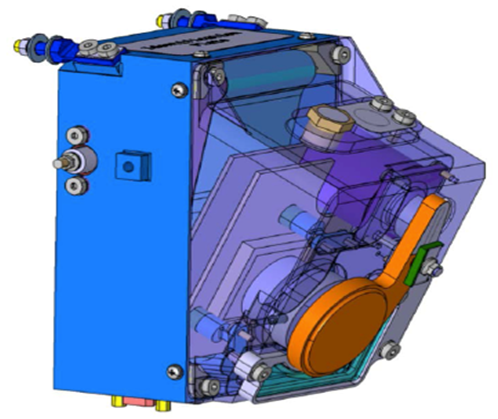
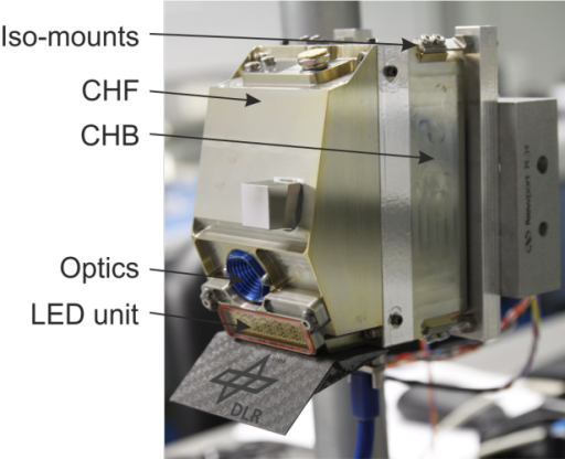
The optical imaging system of the MASCOT lander is a wide-angle camera to be used for structural, textural and compositional characteristics ranging from several meters to a millimeter scale, also providing context images for the other lander instruments. The camera will also work as a descent imager to close the resolution gap between HY-2 images and in-situ images collected from the ground.
The camera has a field of view of 55 degrees facing downward when the lander is in its correct orientation, however, the camera is canted by 22 degrees with respect to the surface plane of the instrument which means that the surface close to the lander, just 15 centimeters from the camera, as well as the horizon are in the field of view. To ensure that the entire scene is in focus, the camera employs the Scheimpflug principle focusing from 15 centimeters to infinity.
The camera is equipped with a CMOS detector that is 1024 by 1024 pixels in size covering a spectral band stretching from 400 to 1000 nanometers with a maximum between 600 and 700 nm. Using an f/16 optics system, the camera achieves a resolution of 150 microns per pixel at 15 centimeters limited by diffraction in the optical components. This allows a close-up look at the properties of the surface.
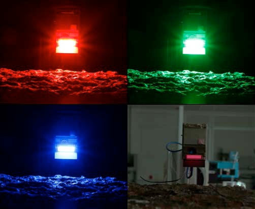
Imaging during the day time will be done to analyze the structure of the surface using the monochromatic images of the camera. At night, artificial illumination is used for color/multiband imaging. An array of 4 by 36 Light Emitting Diodes is installed on the lander to illuminate the surface in the field of view of the camera at specific wavelengths of 470 (Blue), 530 (Green), 624 (Red) and 805 nanometers (Infrared). Spatial distribution and spectral calibration of the LEDs was completed pre-flight.
The entire payload weighs just 403 grams and requires a peak power of under 6.4 Watts during multiband imaging. A movable cover protects the camera during the touchdowns of the lander. Each image will be 14.7 Mbit in size, limiting the number of images that can be uplinked to the HY-2 spacecraft. It is planned that several images will be taken during the descent and during each of the hops, plus five images per day and four (RGB,IR) images per night.
MicrOmega
MicrOmega is a near infrared spectrometer payload coupled with an hyperspectral infrared microscope for in-situ mineralogical analysis performed on the asteroid’s surface. The aim of the instrument is to make detailed grain size measurements and characterize the composition of the surface. The instrument uses elements developed for the first MicrOmega built for Phobos-Grunt and a similar unit to be flown on the ExoMars rover. The entire instrument, including its electronics assembly, weighs around two Kilograms.
The instrument will collect reflectance spectra of a 5 by 5-millimeter surface spot with a spatial sampling distance of 20 micrometers using a 128 by 128 pixel array detector. The system uses an AOTF-based dispersive system.
An AOTF (Acousto-Optic Tunable Filter) is an electro-optical device that serves as an electronically tunable spectral bandpass filter with no moving parts. It uses a crystal in which Radio Frequency Waves are used to separate a single wavelength of light from a broadband source. The output wavelength is a function of the RF frequency that is applied to the crystal which can be varied.
Usually, an oscillating electrical signal is used to drive the piezo-electric transducer that vibrates to create acoustic waves in the crystal which change the index of refraction of the material so that incoming light scatters. (The crystal lattice is alternately compressed and relaxed which allows the medium to act like a diffraction grating but with the advantage of only diffracting one specific wavelength that is selected by altering the RF.) Beam stops are implemented to block the zero-order beam and one of the polarized first-order beams to direct the first-order beam with the desired polarization to the experiment.
Within the spectrometer, the AOTF acts as the monochromator. This design provides a number of advantages including long-term wavelength repeatability, extremely high wavelength purity, fast response to RF changes so that spectra can be recorded within seconds, high efficiency and long service life (no moving parts).
The intensity of reflected light at each selected wavelength is detected to create the spectra that are used to determine target composition and mineral abundance. The two-dimensional detector of the MicrOmega instrument uses a mercury-cadmium-telluride array that is cooled by a dedicated cryocooler to achieve the required low dark current.
The instrument covers a spectral range of 0.9 to 3.5 micrometers with steps of 20/cm. Data products are 3D images that, for each pixel, contain a full spectrum to allow the characterization of individual grains.
The spectral range and resolution of the instrument allows the identification of most potential constituents of the surface including silicates, oxides, salts, hydrated minerals, ices and frosts as well as organic compounds that are the focus of the entire mission to a C-type asteroid.
MicrOmega can differentiate between specific members of mineral families and also distinguish the different classes of organic compounds. Organics, if found, will be put into context to evaluate in which mineralogical environment they nucleated to better understand the processes that were at work when the asteroid was formed and how it evolved. Particular interest is also on volatiles that may have played a major role in the development of the Solar System.
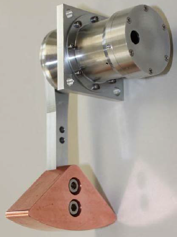
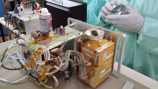
MASCOT Radiometer – MARA
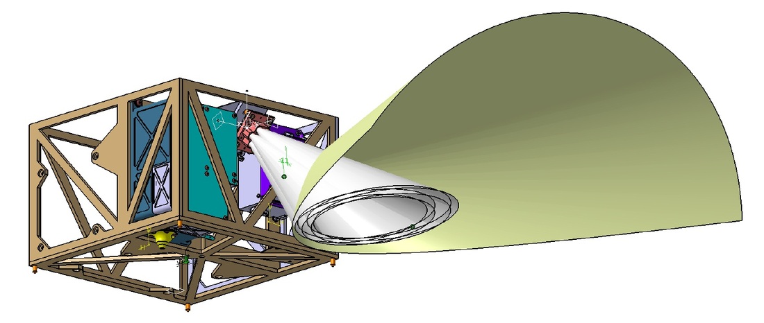
MARA is a radiometer designed to measure the radiative flux emitted from the asteroids surface to determine the surface brightness temperature for a full rotation period. The instrument will also provide data for the determination of the thermal inertia of the surface and the asteroid’s energy balance which are critical data points for geologists to gain insight into the properties of the surface and the formation and evolution of the asteroid. A secondary objective of the instrument is the study of band ratios in selected wavelength bands to deliver additional data on landing site mineralogy.
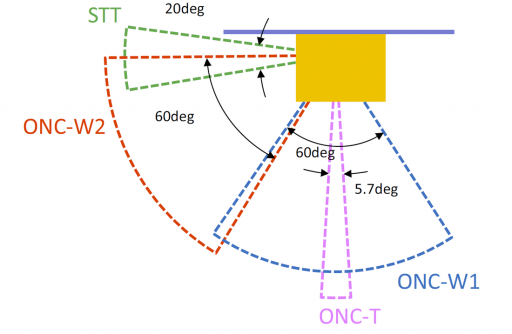
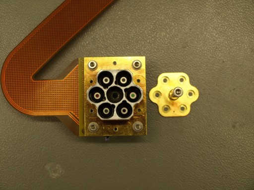
The MARA sensor head facilitates six thermopile sensors, each with a field of view of 20 degrees. Each PT100 sensor has its own individual absorber and filter to allow the sensors to cover different wavelength bands. The sensor head features a gold coating for lower emissivity to save power for heating that is needed to ensure a good signal-to-noise ratio. MARA’s field of view covers a portion of the field of view of the MASCOT Camera to provide context imagery of the area that is radiometrically studied.
The thermopile voltage is generated by 72 bismuth-antimony thermopair junctions with an absorber diameter of 0.5 millimeters.
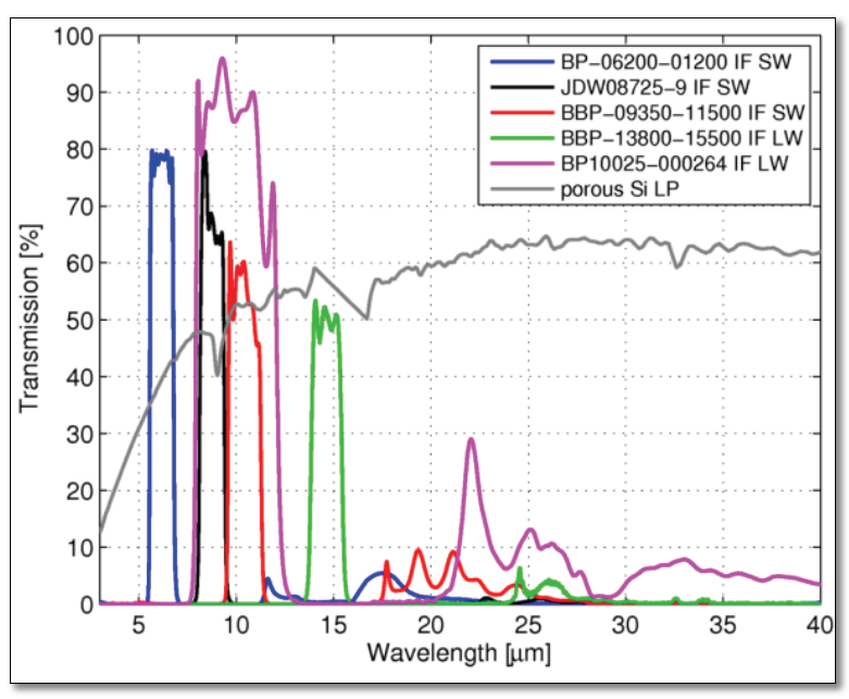
A single long-pass channel covering a spectral range of 5 to 100 µm is used to measure the surface brightness temperature. Another channel at 8 to 14 µm covers the same band as the TIR instrument of the orbiter and provides a ground-truth data point for the orbiter instrument for context in data processing. Cross-calibration of the two instruments has taken place prior to flight. The other four MARA channels are: 5.5-7, 8-9.5, 9.5-11.5, and 13.5-15.5 µm. These four channels are dedicated to a mineralogical surface characterization since rock-forming minerals such as olivine and pyroxene have characteristic absorption features in these bands.
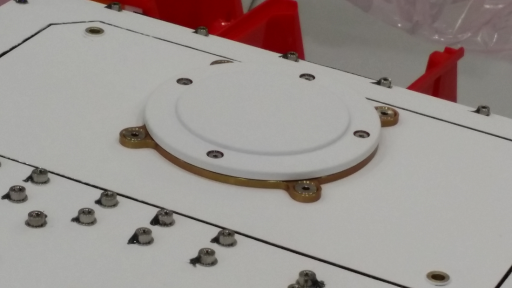
During the cruise phase, a calibration target is located in the field of view of MARA to allow in-flight calibration and tracking of sensor drift. The calibration target has an emissivity of over 95% and includes heaters and temperature sensors to provide a good in-flight calibration. It remains with the HY-2 spacecraft after lander separation.
CAM & MARA Fields of View
MASCOT Magnetometer
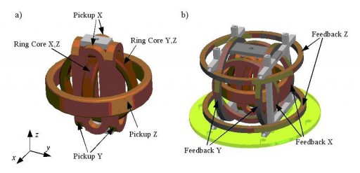
The MASCOT lander’s Magnetometer consists of a three-axis fluxgate magnetometer that will determine the magnetic field of the asteroid during descent and the hops of the lander to get an overview of macroscale magnetic properties and the global magnetic field. When on the ground, the instrument can determine the local magnetization at very small scales, also tracking variations that may occur as a result of any external influences.
The fluxgate sensors use the nonlinearity of magnetization properties for the high permeability of easily saturated ferromagnetic alloys to serve as an indicator for the local field strength. The ferromagnetic material is surrounded by two coils of wire – one coil runs an alternating electrical current which drives the core through an alternating cycle of magnetic saturation. This changing field induces a current in the second coil which can be measured by a detector.
In a magnetically neutral environment, the input and output currents would be identical, but the presence of an external field leads to an easier saturation of the core when in alignment with the core while saturation is less easily achieved when the core is exposed to an opposing field. This leads to the output current becoming out of step from the input which, with the known parameters of the core material and the simultaneous measurement of the input, will provide information on the local field strength using known calibration data.
The instrument consists of a Field Programmable Gate Array that controls the driver coil and receives the output from the detector coil. The controller provides all timing, commanding, data processing, analog to digital conversion and data relay to the lander’s onboard computer.
The measurement channel provides an excitation feedback in addition to the integrated measurement of magnetic permeability while the driver channel sweeps through a voltage range and measures the current in the coil.
The system operates at a dynamic range of +/-50,000 Nano-Tesla with a resolution of 6 Pico-Tesla and a sampling rate of ten measurements per second. The instrument has a mass of 243 grams, it is 5 by 7 by 7 centimeters in size and requires just 1.2 Watts of power, allowing the instrument to operate continuously.
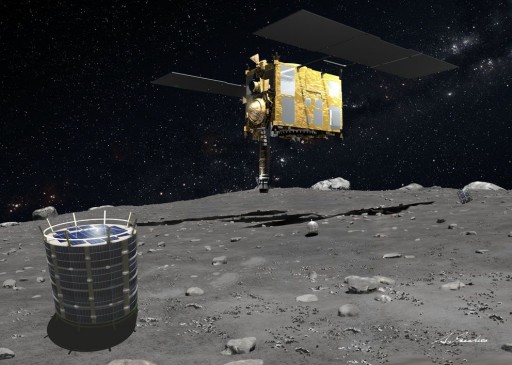
MINERVA-II
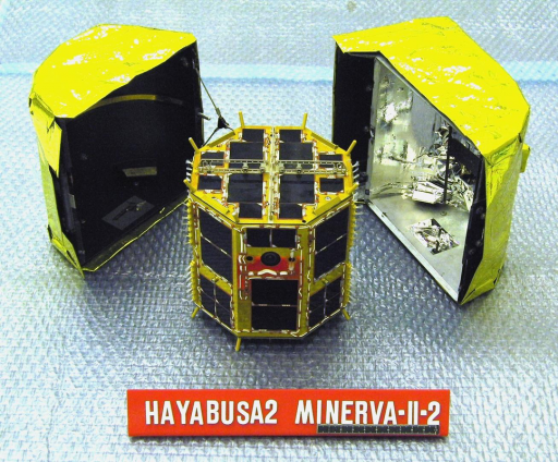
The MINERVA-II rovers, or rather ‘asteroid hoppers,’ are based on the original MINERVA craft flown on Hayabusa 1, but did not have success in landing on the surface of the asteroid due to an error in the delivery of the small vehicle. MINERVA-II-1 consists of two rovers that separate from one another after release from the HY-2 spacecraft while MINERVA-II-2 is a single unit aiming to land on the surface.
MINERVA weighs 2.5kg (II-1) and 1.6kg (II-2) Kilograms and the basic unit measures ten centimeters in size, being hexadecagonal in shape. It hosts a RISC Central Processing Board that includes 512kbyte of ROM holding the boot code and flight software, 2MB of RAM and 2MB of Flash Rom for the storage of collected data.
The entire surface of the lander is covered in solar cells that create a maximum power of 2 Watts that is used to run the processor and charge double layer capacitors that act as batteries and are needed for the operation of the communications system, the actuators and the payloads.
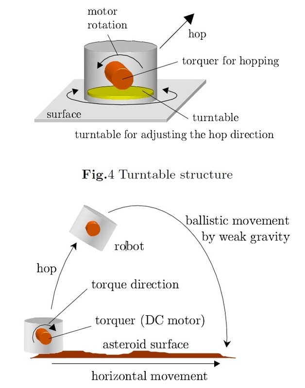
MINERVA can hop from one location to another using two DC motors – the first serving as a torquer, rotating an internal mass that leads to a resulting force, sufficient to make the rover hop for several meters. The second motor rotates the table on which the torquer is placed in order to control the direction of the hop. The rover reaches a top speed of 9 centimeters per second, allowing it to hop a considerable distance. Communications with the Hayabusa spacecraft are accomplished at data rates of up to 9,600 bits per second.
Each of the MINERVA landers carries a series of instruments including cameras, photodiodes, and temperature sensors.
Images created by the cameras are thumbnail sized due to the low data speeds and MINERVA employs an onboard image processing tool that cuts any parts of a picture that do not contain a scene to minimize uplink volume. Surface temperature measurements at different locations and at different times of day are of great interest to scientists to better understand the energy balance of the asteroid and its surface material.
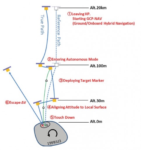
Hayabusa 2 Flight Profile