
Quasi-Zenith Satellite System (QZSS)

Japan’s Quasi-Zenith Satellite System (QZSS) is a satellite-based augmentation system for the Global Positioning System and Galileo Navigation Satellite Systems to enhance their accuracy and availability over Japan by placing four satellites into specialized and non-specialized Geosynchronous Orbits in order to achieve high viewing angles over all Japanese islands.
QZSS was initiated by the Japanese Government back in 2002, starting development work under the auspices of the Advanced Space Business Corporation (ASBC) – an industry consortium comprised of Mitsubishi Electric, Hitachi and GNSS Technologies Inc.
However, the consortium dissolved in 2007 and work was taken over by the government’s Satellite Positioning Research and Application Center.

Initially, QZS was planned to be part of a complex multi-mission concept consolidating various communication services, positioning, navigation and timing into a single program. This was abandoned in favor of creating lower-cost satellites purely dedicated to PNT (Positioning, Navigation, and Timing) and placing them into optimized orbits. JAXA, the Japan Aerospace Exploration Agency, was tasked with developing the system concept and Japan received clearance from the United States in 2006 for the use of the GPS frequency bands and signal architecture.
Initially, the operational QZSS system was envisioned to be a three-satellite constellation with one satellite at high-elevation over Japan at any given time. Early in the development process, the constellation was expanded to four satellites with the fourth satellite positioned in Geostationary Orbit to deliver GPS augmentation services to the entire Asia-Pacific Region. Later on, the Japanese government decided to further expand the constellation in the 2020s to seven active satellites with two satellites located high-over Japan at any given time.

The first QZS satellite, nicknamed Michibiki (=to guide, to show the way) was launched atop an H-IIA rocket in 2010 to complete a multi-year test mission to fully verify the concept of the QZSS design that takes a unique spot in the satellite spectrum in that it is designed to augment another satellite constellation but moves beyond acting as a bent-pipe relay of ground-generated augmentation signals and in-fact delivers navigation signals of its own.
Positioning services delivered by QZSS are intended as GNSS Augmentation and not as a stand-alone system, increasing the availability of GPS services across Japan and enhancing navigation accuracy for high-precision application in aviation and mapping. To accomplish its objectives, QZSS transmits GPS-interoperable signals to improve availability while separate augmentation signals are used in high-precision applications.
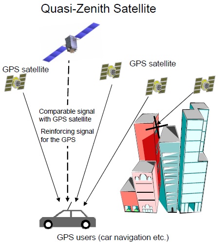
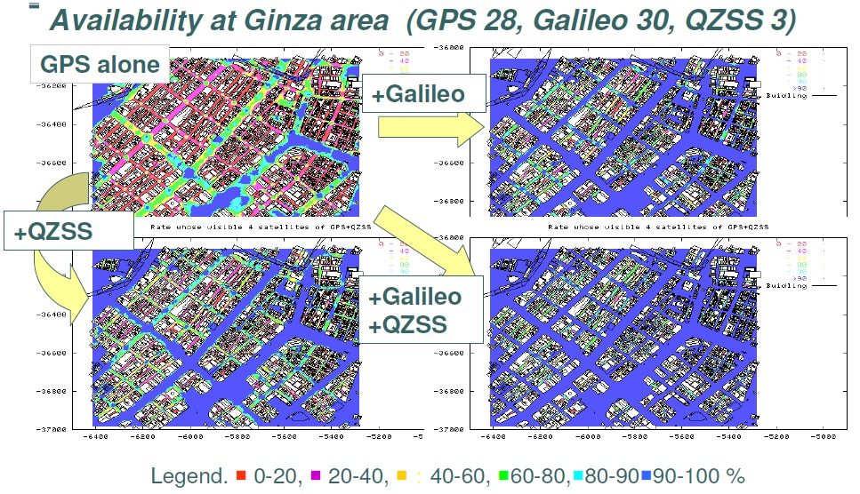
The primary purpose of QZSS to increase the availability of GPS in Japan’s urban canyons where satellites have to be at very high elevation angles to have a direct line of sight to users on the ground.
Therefore, QZSS uses a highly specialized orbit that ensures one of the satellites is almost directly overhead at any given time – as seen from the Japanese territory. The second function of QZSS is GPS performance enhancement, increasing the accuracy and reliability of navigation solutions.

The QZSS spacecraft transmit signals fully compatible with the GPS L1C/A and modernized L1C, L2C and L5 signals, requiring no changes to existing GPS receivers on the ground. These signals are identical to the GPS constellation, allowing a receiver to treat a QZS satellite like a member of GPS. Performance-enhancement signals, designated L1-SAIF and L-EX, are processed by specially equipped GPS/QZSS receivers to derive correction information plus information on GPS signal reliability.
The QZS System comprises a space and ground segment. Naturally, the space segment includes the constellation satellites operated in a specialized Geosynchronous Orbit that enables them to spend the majority of time over the Japanese Islands. The ground system includes a Master Control Station, a Monitoring Station, Tracking and Control Stations and systems of other national research institutions aiming to study the behavior of atomic clocks in space.

Ten tracking and control stations will be deployed across Japan and overseas to a) track the variation of GPS signals for correction signal generation, b) provide accurate orbital tracking for the QZS satellites for ephemeris generation, and c) deliver clock correction data to the satellites.
The first QZS Satellite, launched in September 2010, made use of the ETS-8 (Engineering Test Satellite 8) satellite platform – creating a 4,100-Kilogram spacecraft with full redundancy in most of its payload and support systems to guarantee robust operation over the initial checkout and validation sequence before serving within the operational QZS constellation. QZS-2 and 4 will weigh in at 4,000 Kilograms and use the modern DS-2000 satellite platform by Mitsubishi Electric while QZS-3, also utilizing DS-2000, will weigh around 4,700kg at liftoff for a 15-year service life from a standard Geostationary Orbit.

QZS-1 completed initial signal verification in October 2010 and entered a multi-month calibration and fine-tuning sequence before all signals from the satellite payload were moved into active operation in July 2011. Initial analysis showed the QZS satellite improved navigation accuracy using the L1 code by a factor of 1.7 to 2.5. The $526 million contract between JAXA and Mitsubishi Electric for the three operational QZSS satellites was closed in 2013 with an in-service date of the operational constellation in mid-2018.
The navigation payload of the QZS satellites is made up of a pair of Rubidium Atomic Frequency Standard (RAFS) clocks, L-band Transmission Subsystem (LTS), Time Transfer System (TTS) and a Laser Reflector Array (LRA) for precise orbit determination as required for the generation of accurate satellite ephemeris.
The redundant clocks are coupled to Time Keeping and Synthesizer Units to deliver ultra-precise timing to the Navigation Onboard Computer which builds the heart of the navigation payload and is in charge of generating navigation messages (PRN Code) then delivered to a Modulator and Amplifier for transmission via the L-Band antennas. The computer also processes the GPS augmentation messages sent up from the ground and relayed by the satellite in a bent-pipe mode. It is also in charge of commanding the clocks and conditioning systems telemetry delivered to the satellite platform.
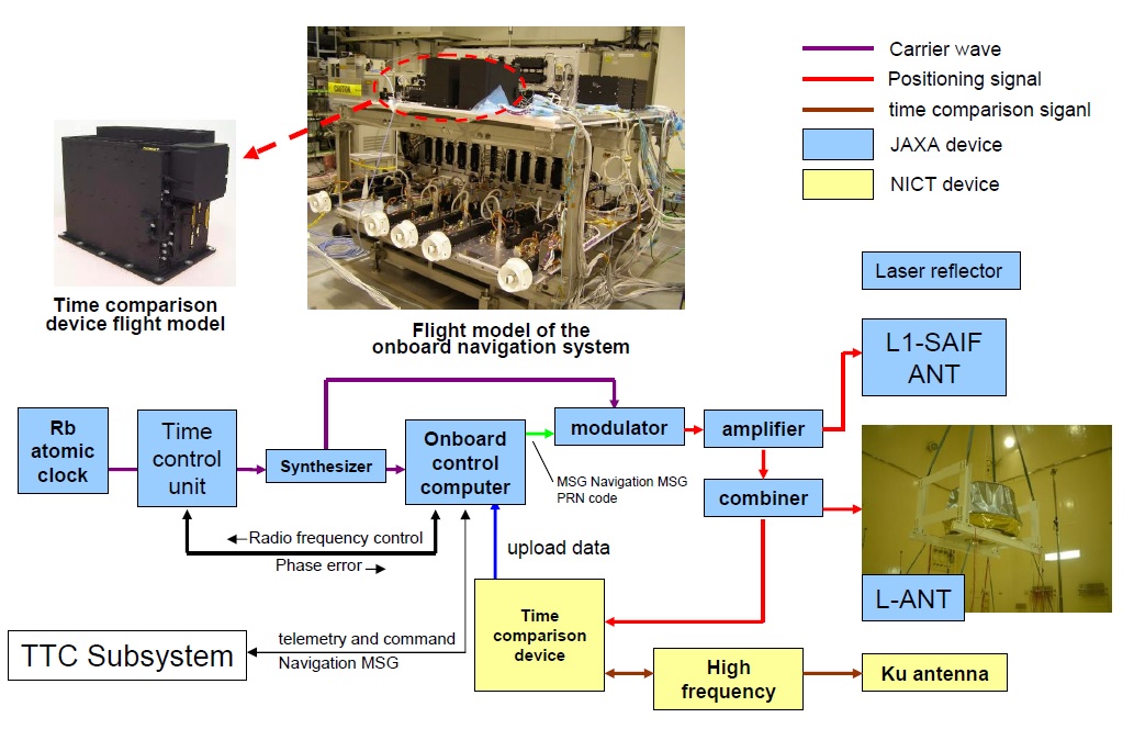
The Time Keeping System uses a Voltage-Controlled Crystal Oscillator with a high short-term stability and the twin clocks with long-term stability to output a standard signal with high stability level. The Time Transfer System compares the difference between the spacecraft time and the ground using a Ka-Band system. QZSS compensates for the ground-station-to-satellite delay through prediction using orbit propagation.
The QZS satellites transmit six signals in four frequency bands, including GPS-interoperable navigation signals and GPS augmentation messages. Interoprable GPS-signals provided by QZSS are the L1C, L1-C/A, L2C and L5 signals; the augmentation signal is known as L1-SAIF (Sub-meter class Augmentation with Integrity Function, compatible with the U.S. WAAS augmentation system), and finally, QZSS supports an L-Experimental signal in the E-6 band (also for augmentation).
Precision application of GPS signals for navigation at a high accuracy requires correction for a number of factors that can cause a slight variation of GPS signals. These include position-independent corrections for errors in the GPS Satellite’s instantaneous position and clock errors as well as position-dependent corrections for signal alteration by Earth’s ionosphere and atmosphere. A second group of corrections, known as slow corrections, include long-term satellite position and clock error estimates.
Ground stations across Japan and surrounding regions constantly monitor the GPS signals for the generation of correction messages that are then sent to the QZSS satellites for immediate-rebroadcast to all augmentation-enabled receivers in the coverage area with an overall turnaround of under five seconds. Augmentation messages include information such as differential correction, satellite orbit error, ionospheric delay and other parameters.

The L1-SAIF signal at 1575.42 MHz is fully compatible with the GPS-SBAS and WAAS system while the L-EX signal at 1278.75 MHz provides a high-data rate signal (kbit/s) and is compatible with the E6 signal band of the European Galileo satellites – allowing QZSS to serve as an augmentation constellation for both GPS and Galileo. Through the standard SAIF augmentation, GPS users can achieve a navigation accuracy of one meter in the lateral direction and 1.5 meters vertically, L-EX could enable surveying applications with an accuracy of a few centimeters.
In addition to standard L1-SAIF messages, QZSS in 2013 introduced a SAIF+ signal which comprise two message types – one that is compatible with the legacy SBAS architecture while the second type enables users to have significantly shorter TTFF (Time To First Fix). The functions of SAIF+ include faster position acquisition, the normal SAIF orbit & clock error correction, and short messages that can be used for search and rescue or disaster relief. SAIF and SAIF+ are planned to be transmitted in parallel.
Based on the DS-2000 satellite platform of Mitsubishi Electric, the QZS satellites stand 6.5 meters tall and are 2.8 meters wide, measuring 19 meters from tip to tip with their two solar arrays fully deployed. The QZS-2 and 4 satellites have a 1,180-Kilogram platform, 370kg payload and carry 2,450kg of propellant for the climb from their initial transfer orbit to the target IGSO. QZS-3 employs a 1,215kg platform, 475kg payload and 3,000kg propellant load for the transition into Geostationary Orbit and 15-year service life.
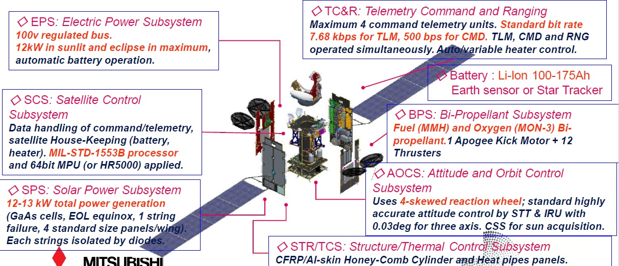
MELCO’s DS-2000 satellite platform originated in a satellite design of the Japan Aerospace Exploration Agency that was modified by Mitsubishi Electric to create a versatile geostationary satellite platform for use in commercial communications satellites, weather satellites, data relay craft and navigation satellites. DS-2000 first flew in 2002 and is highly regarded across the commercial space sector for its excellent reliability and projected mission durations in excess of 20 years.
DS-2000 can support a payload power of up to 15 Kilowatts and has been baselined for a 100-Volt power bus that implements redundancy to ensure all equipment of the satellite receives electrical power. Power storage is typically accomplished with a 175 Amp-hour battery unit and dedicated electronics are used for power distribution and bus protection.
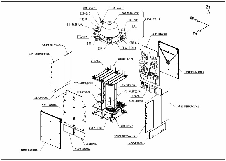
Structurally, the satellite consists of an internal cylinder that builds that load-bearing structure of the spacecraft and facilitates the propellant tanks. From the cylinder extends a network of struts and panels made of Aluminum skin Carbon-Fiber-Reinforced Plastic, used to provide mounting surfaces for the various subsystem components.
Attitude determination primarily relies on a Star Tracker system and Inertial Reference Units as well as Earth and Sun Sensors used during initial acquisition and safe mode. Using a Reaction Wheel Assembly consisting of four wheels, the satellite has a pointing accuracy of 0.03 degrees for precise Earth-oriented operation. Thermal control equipment on the satellite includes external radiators and internal heaters to maintain an operational environment for all satellite components.
DS-2000 features a liquid-fueled propulsion system consisting of an Apogee Engine and a dozen attitude control thrusters. The main engine is located on the aft side of the spacecraft and is used to perform a series of apogee maneuvers to boost the satellite from an elliptical Geostationary Transfer Orbit into a nearly circular Geostationary Orbit. Engine options available for the DS-2000 satellite bus are the 490-Newton R-4D and 450-Newton BT-4 engine, both use Monomethylhydrazine and Nitrogen Tetroxide/MON as propellants.
Orbit
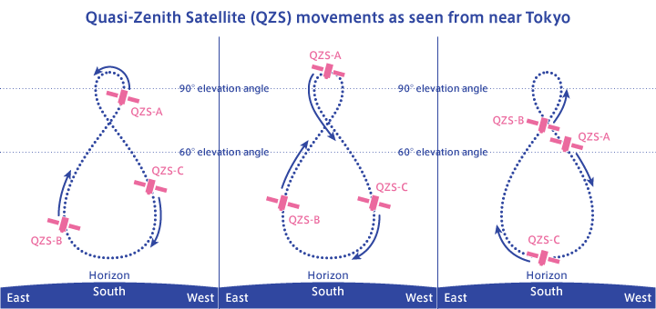
The core objective of the Quasi Zenith Satellite System is to enable GPS enhancement through providing a high-elevation source of navigation signals for the Japanese territory. This requires the satellites to operate in a highly specialized orbit that provides a maximum dwell time around 42 degrees north latitude to allow a satellite to spend as much time as possible directly overhead (zenith) for most users in Japan.
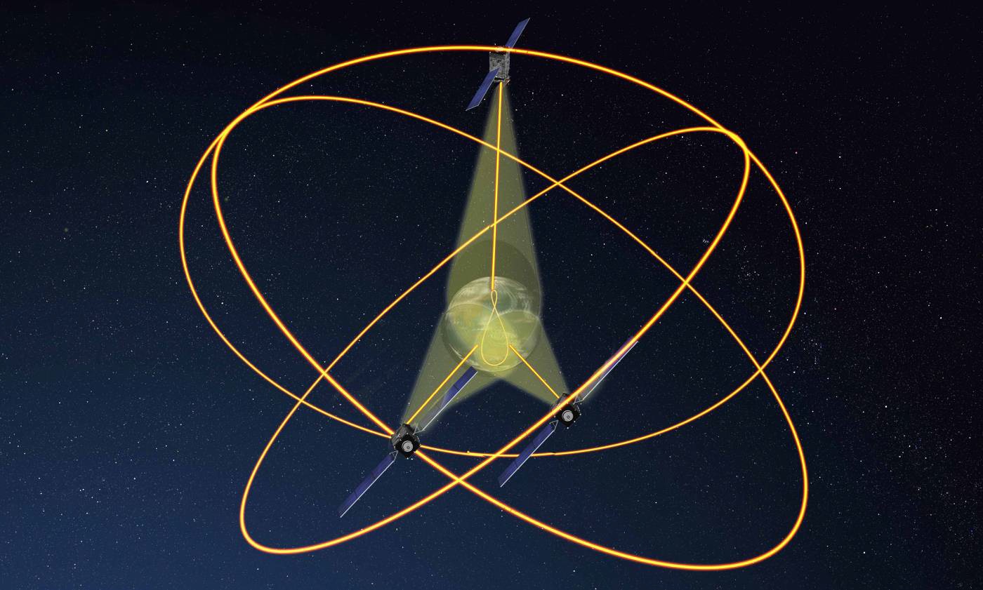
QZSS makes use of a highly inclined, slightly elliptical Geosynchronous Orbit that is also known as a Tundra Orbit, named after the Russian Tundra missile warning satellites that were initially expected to use this type of orbit. This orbit is not to be confused with a Geostationary Orbit which has the same period but is designed to keep satellites in a fixed position in the sky, instead, the QZSS satellites do not remain in the same place in the sky but spend extended periods over Japan.
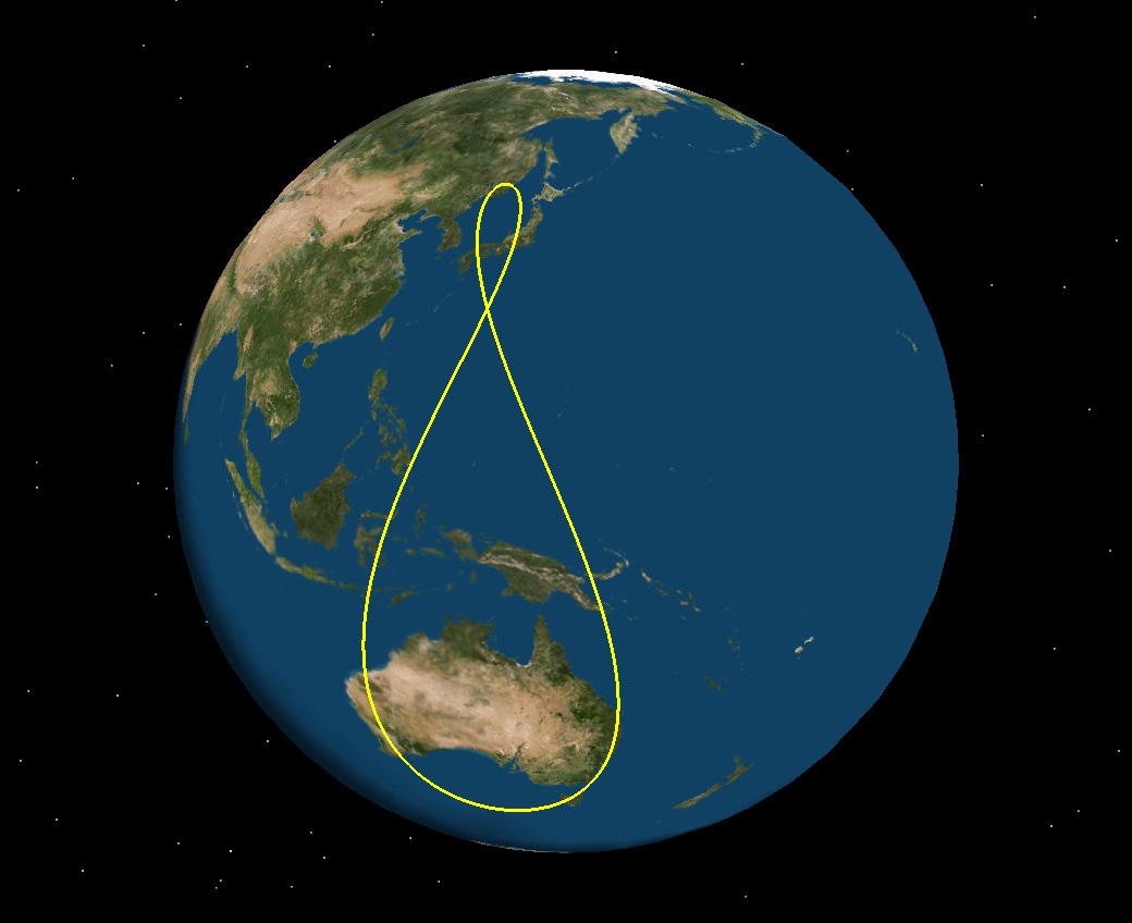
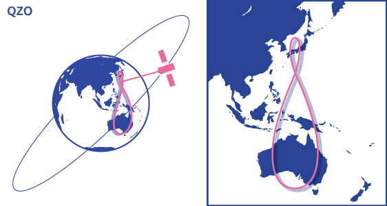
As an inclined Geosynchronous Orbit, the QZSS orbit has a period of exactly one sidereal day so that the satellite passes its apogee (high point) over the same high-latitude location every day. Since the satellite’s speed (relative to Earth) is lowest around the peak altitude of its orbit, it spends the majority of time around the high-point of its orbit, known as apogee dwell. Forming an asymmetrical Figure 8 (Analemma) with its ground track, a satellite in a Tundra orbit reaches very high elevation angles for the high latitudes which is not possible from Geostationary Orbit over the equator.
The QZS satellites employ an orbit of approximately 32,600 by 38,950 Kilometers (eccentricity ~0.8) at an inclination of 43 degrees (+/-4 degrees), typically around 41°, and with a central longitude of 135°. With three satellites spaced at 120 degrees in the QZSS type orbit (RAAN & Mean Anomaly), there is at least one satellite at an elevation of 60 degrees or higher.
One issue suffered by the QZSS satellites is a constant perturbation caused by Earth’s equatorial bulge which causes the argument of perigee to slowly change over time, resulting in a precession of the orbit’s apogee location which is either accepted as this progression occurs over a period of years or requires periodic orbit modifications.
The Figure 8 prescribed by the QZSS orbit takes the satellites as far north as Hokkaido where they pass their peak before descending toward perigee located just south of Australia. Their ground track takes the satellites almost directly over Tokyo, yielding extremely high-elevation angles over Japan’s capital where almost a third of the country’s population resides.
A very similar system was operated by satellite radio provider Sirius between 2000 and 2016 with three satellites in even more eccentric (elliptical) orbits peaking over Canada and allowing the satellites to directly transmit to ground-based receivers, even in between tall buildings – reducing the number of terrestrial repeater stations to a minimum. The constellation was designed to operate each satellite for around sixteen hours per day with two satellites at sufficient elevation angles for the North American sector at any given time.
Sirius switched to a pure Geostationary System with its next generation of satellites to ensure a more consistent reception for fixed-location users.
