KOMPSAT-3A
KOMPSAT-3A is part of the Korean Multipurpose Satellite Program developed and operated by the Korea Aerospace Research Institute KARI to establish an operational Earth observation capability that includes satellites carrying optical, infrared and radar payloads to deliver data needed for a variety of purposes. The 3A satellite carries an optical imaging system sensitive to wavelengths in the visible and infrared range, building on the KOMPSAT-2 and 3 satellites that carried similar payloads.
The first KOMPSAT mission was launched in 1999 featuring a 470-Kilogram satellite that carried an optical imager with a ground resolution of 6.6 meters. KOMPSAT-2, weighing in at 800kg using a newly developed satellite bus, launched in July 2006 and delivered imagery at a 4-meter ground resolution covering four spectral bands and employing off-nadir imaging techniques. The KOMPSAT-3 satellite was launched in 2012 using a similar bus architecture as KOMPSAT-2 but an improved optical payload that reached a resolution of one meter for panchromatic imagery. In 2013, a Dnepr rocket launched the 1,420-Kilogram KOMPSAT-5 satellite, becoming the first radar satellite of the fleet, outfitted with a 9.66GHz Synthetic Aperture Radar capable of covering a wide ground swath or operating in a high resolution mode delivering imagery at a one-meter resolution.
KOMPSAT-3A is the sister of KOMPSAT-3, using an identical satellite bus and payload with the only difference being an added infrared capability. The satellite will expand the existing constellation and ensure data continuity after KOMPSAT-3 reaches is planned End-of-Life date after three to five years of operation. The main purpose of the optical KOMPSAT spacecraft is to deliver high-resolution imagery for Geographical Information Systems as well as environmental, agricultural and oceanographic monitoring.
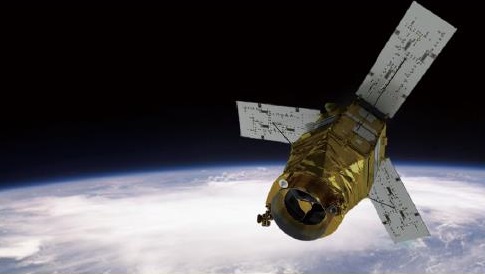
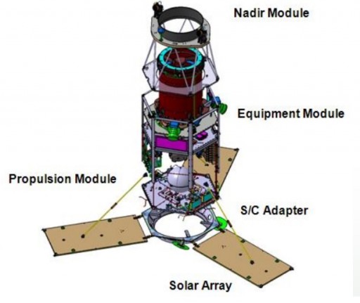
The satellite bus consists of a hexagonal platform and a cylindrical nadir module hosting the optical payload systems. Beginning in the aft, the satellite consists of a Spacecraft Adapter interfacing with the launcher, a Propulsion Module, an Equipment Module and the Nadir Module. The satellite has a mass of just under 1,000 Kilograms measuring 2.0 meters in diameter and standing 3.5 meters tall.
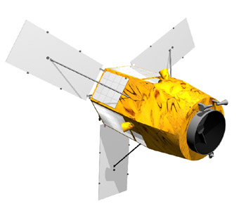
KOMPSAT-3A is outfitted with three power-generating solar panels – each installed on two hinges on the aft deck of the satellite, allowing the panels to be deployed by two extendable booms that interface with the Equipment Module. The panels are rigid and can not be moved to track the sun. Using gallium-arsenide solar cells, the panels face to the aft of the satellite so that the optical payload is not subjected to solar radiation when in a sun-pointing orientation used for power generation.
Overall, the panels deliver 1,300 Watts of electrical power that is passed to power input equipment including an input filter, inrush current limiters and input voltage limiters before being passed to average current mode regulated DC-to-DC converters that generate a 28-Volt main power bus. Secondary voltage generators with 12 outputs deliver various voltages needed for the different electronics of the satellite.
Thermal control of the satellite is accomplished with multilayer insulation and heaters that keep critical components within an operational temperature range. Excess heat generated by electronic systems and the cryocooler of the infrared detector is radiated into space by external radiator panels installed on the equipment module on external panels not hosting solar panels.
The spacecraft is equipped with three different attitude sensors – a series of coarse sun sensors, an inertial measurement unit and star trackers. The coarse sun sensors provide a basic sun vector direction to be used in the event of a spacecraft safe mode to keep the solar panels pointed to the sun to ensure good power generation. The star trackers use optical imaging heads and electronics units to capture imagery of the star-filled sky using a narrow field of view.
Stars in that field of view are compared to a catalog of known star constellations from which the three-axis orientation of the satellite can be determined to provide very precise pointing information. Inertial measurement data is used to measure body rates used to reduce spacecraft motion to allow the star trackers to acquire star patterns which requires low body rates on the satellite.
Attitude actuation is provided by reaction wheels. The reaction wheel represents a rotating mass that is driven by a motor – when accelerating or decelerating the wheel, the satellite body will move into the opposite direction as the result of induced counter torque. To allow de-spins of the wheels, the satellite uses magnetic torquers that use the Earth’s magnetic field to create a force that counters that of the de-spinning wheel to desaturate the reaction wheels at regular intervals. The attitude control system achieves a pointing accuracy of 0.025 degrees and can support quick slew maneuvers up to +/-45 degrees off nadir. Position and velocity measurements are provided by a GPS unit.
Orbit corrections and maintenance are supported by a Hydrazine propulsion system that consists of a central Hydrazine tank, a pressurization system and two thruster banks of four 4.5-Newton thrusters. The thrusters use the catalytic decomposition of Hydrazine monopropellant over a heated catalyst bed to generate thrust.
The satellite facilitates an S-Band communications terminal for the uplink of command sequences from the ground and the downlink of status telemetry and payload housekeeping data. A high-speed X-Band system is used to downlink acquired imagery from a large solid-state memory module.
KOMPSAT-3A is equipped with two imaging payloads – the Advanced Earth Imaging Sensor System A (AEISS-A) and an Infrared Imaging Payload. AEISS-A is similar to that of the KOMPSAT-3 spacecraft and was developed by KARI with technical support from Astrium Defence and Space and the German Aerospace Center that developed the Focal Plane Assembly and main Camera Electronics Unit.
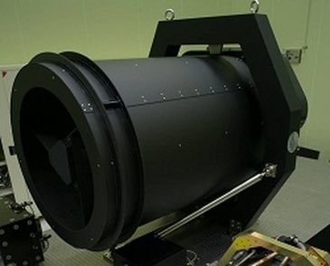
AEISS-A consists of an Optical Module and Camera Electronics Unit which itself is comprised of a power supply, a camera controller and the Focal Plane Assembly. The electronics interface with the onboard computer via a 1553 data bus to exchange commands and housekeeping data. The Optical Module is cylindrical in shape, enclosed in a Carbon Reinforced Plastic structure that provides a high thermal stability and structural stability which is also provided by support struts to ensure the telescope structure remains in place with tolerances of a few micrometers. The two star trackers of the spacecraft are installed on the aft segment of the cylindrical optical unit. The optical unit measures 1.3 by 2.0 meters and has a mass of around 80 Kilograms.
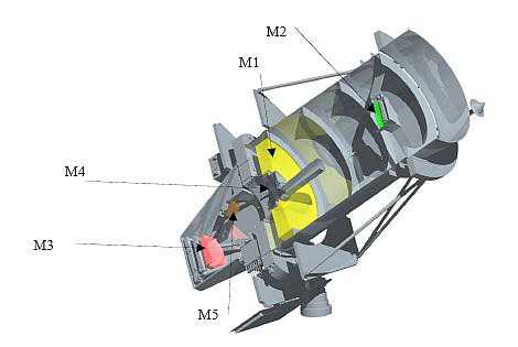
The telescope uses a Korsch combination with three aspheric mirrors and two folding mirrors using an aperture diameter of 80 centimeters. This design was chosen because of its simplicity and compact size – fitting within the small spacecraft platform. An entrance baffle is used for stray light rejection. Light entering the instrument passes through a Cassegrain-arrangement with an on-axis system of the concave M1 primary mirror and an on-axis convex M2 secondary mirror. The light then passes to an off-axis M3 mirror (concave) reflecting the light to an on-axis M4 aspherical concave mirror passing it on to the M5 folding mirror focusing the radiation onto the Focal Plane Assembly. The additional M3 and M4 mirrors create a focal length of 8.6 meters.
The telescope mirrors are installed on a Carbon Fiber Reinforced Plastic structure while the mirrors themselves consist of Zerodur that provides an extremely high thermal stability with low thermal gradients throughout the structure.
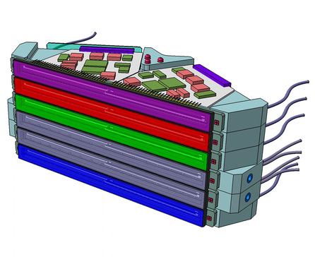
The Focal Plane Assembly of the AEISS instrument features a stacked architecture – with two Focal Plane Modules dedicated to the panchromatic band covering a wavelength range of 450 to 900 nanometers. The two PAN modules are operated in cold redundancy with one module active at a given time. The remaining four Focal Plane Modules are covering the four multispectral channels of AEISS – a blue channel (450-520nm), green (520-600nm), red (630-690nm) and near infrared (760-900nm).
The panchromatic line array detector consists of 12,000 pixels per module using a Time Delay Integration in four stages creating a raw data rate of 3.84Gbit/s. The multispectral channels use 6,000-pixel line array detectors with time delay integration employing pixel binning and delivering data at 240Mbit/s per channel. The optical payload uses anti-blooming techniques and a 14-bit data quantization. After going through onboard processing and compression, data is stored in a solid-state memory for downlink via a high-speed X-Band system.
The Focal Plane Assembly includes an active focus control system that uses heater rings on the lower and upper side of the telescope attachment. Heating the rigs leads to a thermal expansion that allows for a slight displacement of the secondary mirror.
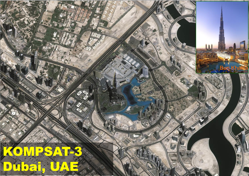
Overall, the AEISS instrument achieves a resolution of around 0.55 meters for panchromatic imagery and 2.2 meters for multispectral images, covering a ground swath of around 15 Kilometers.
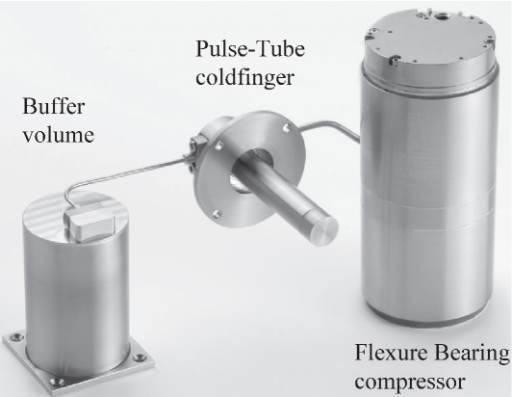
In addition to AEISS also used on KOMPSAT-3, the 3A satellite hosts an infrared imaging system delivered by AIM. Using a cryo-cooled pushbroom sensor, the system covers a mid-wave infrared wavelength range of 3 to 5 micrometers. The detector array consists of Mercury-Cadmium-Telluride (MCT) pixels hybridized with the Read-Out-Integrated-Circuit (ROIC). The infrared detector is cooled to 80K by using a pulse-tube cold finger to reduce dark currents. Overall, the infrared imaging payload acquires imagery at a ground resolution of 5.5 meters.
KOMPSAT-3A will operate from a 528-Kilometer sun-synchronous orbit at an inclination of 98.5 degrees.
The KOMPSAT ground segment consists of two elements – the Mission Control Element and the Image Reception and Processing Element. The Mission Control Element provides mission planning, spacecraft control, commanding and resource management. It is directly in charge of the reception of S-Band telemetry data from the satellite and the transmission of command sequences to the satellite.
The Image Reception and Processing Element receives the X-Band payload data from the spacecraft and completes ground-based processing to deliver geometric calibrated data products for external users.
KOMPSAT-3 Image