
KazEOSat-2 Spacecraft Overview
KazEOSat-2 is a medium-resolution optical Earth Imaging Satellite built by Astrium Defence and Space and Surrey Satellite Technology for operation by the Kazakh Space Agency to provide data to the government of Kazakhstan to support decision-making and policy in critical area such as resource monitoring, resource management, land-use mapping and environmental monitoring information.
Two KazEOSat spacecraft are launched in 2014, first was KazEOSat-1 also known as DZZ-HR or HRES (High Resolution Earth Observation Satellite) that was delivered to orbit by the European Vega launcher on April 30, 2014. While KazEOSat-1 provides high-resolution imagery, it will be complemented by the lower resolution images of KazEOSat-2 that cover a wider swath and thus reduce revisit times. The KazEOSat-2 satellite is also known as DZZ-MR or MRES (Medium Resolution Earth Observation Satellite).
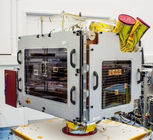
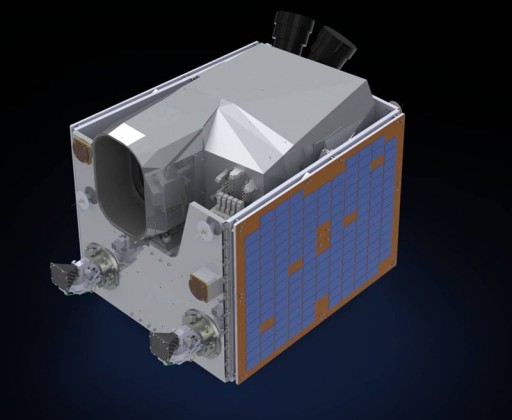
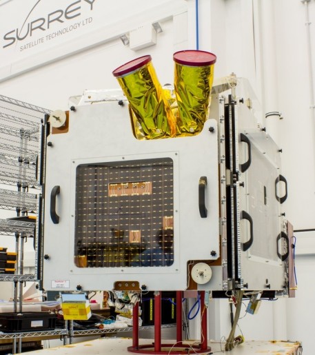
The KazEOSat-2 spacecraft is based on the SSTL-150 small satellite platform that can host a range of optical imaging payloads. Overall, KazEOSat-2 weighs 185 Kilograms and is 70 by 80 by 90 centimeters in size. The satellite bus can support payloads of up to 50 Kilograms with an external payload volume of 73 by 45.5 by 77.4 and an internal volume of 27.95 by 23.15 by 25.25 centimeters. The main payload of the satellite, KEIS acquires images with a resolution of 6.5 meters across a 77-Kilometer ground swath.
The satellite consists of a stack of core avionics systems using a modular design that are supported by microtrays which add mechanical strength to the satellite and provide mounting structures for other satellite equipment. Internal panels are used to support the various subsystems of the satellite. Electrical power is provided by three body-mounted solar panels installed on three sides of the satellite for a total area of 1.15m².
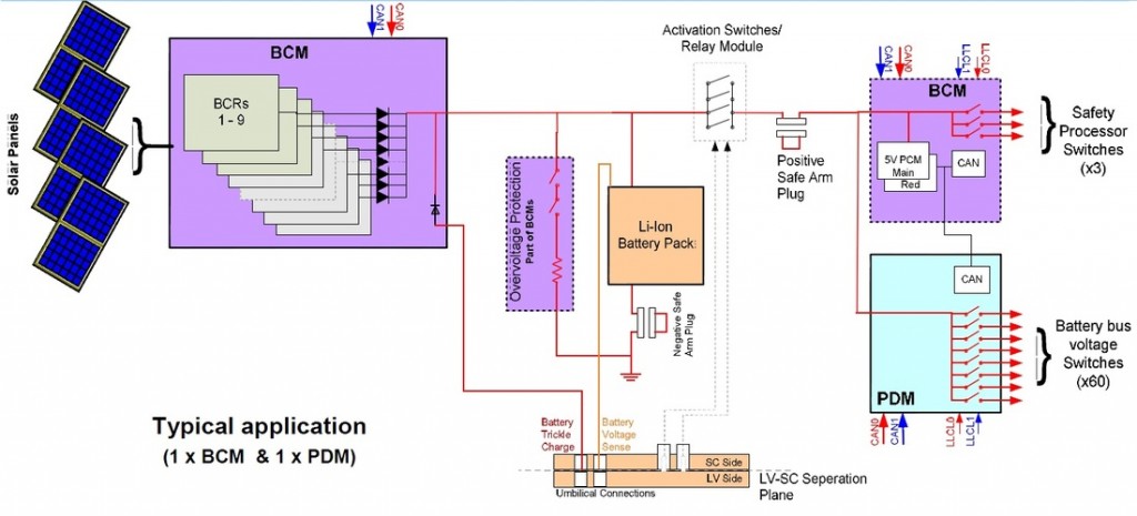
Located on the +x, -z and –x panels, the single-junction Gallium-Arsenide solar cells deliver an average power of 60 Watts at an efficiency of 19.6%. Peak power on the larger x-solar panels is 110W while the smaller z-panel delivers up to 55W. Power is fed to a 15 Amp-hour Li-Ion battery using Battery Charge Regulators to manage the state of charge of the battery. Power from the battery is passed to the Power Conditioning Module and Power Distribution Module that supply an unregulated 28V power bus and a regulated 5V bus and distribute/switch power to all satellite subsystems.
Power System Diagram
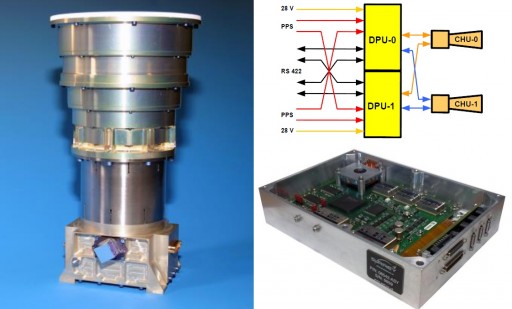
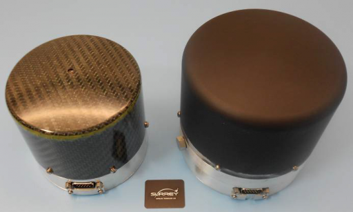
The Attitude Determination and Control System of the Satellite uses a redundant set of sun sensors and magnetometers for coarse attitude knowledge and Rigel-L star tackers for high-precision three-axis orientation knowledge. Rigel-L uses two optical heads and two Data Processing Unit with cross-strapping between the two strings for a high degree of redundancy. The optical heads use 30-degree baffles are 14.7 centimeters in diameter and 28.3 centimeters long. Rigel-L uses Active Pixel Sensors to achieve a field of view of 22.6 by 22.6 degrees and operates at an update rate of up to 16 Hz.
The DPU is 15.5 by 21 by 5.6 centimeters in size weighing under 1.2 Kilograms while the optical head weighs 1.4 Kilograms. The system can acquire three-axis attitude data within eight seconds from power-on with an accuracy of 3 arcsec on X/Y and 25 arcsec on Z. The star trackers are integrated into the spacecraft data system via an RS-422 bus. Alignment errors are eliminated by installing the star trackers onto the optical bench of the payload module.
Sun Sensor & Magnetometer
Attitude actuation is accomplished by using 100SP-M reaction wheels. 100SP-M reaction wheels are 109 millimeters in diameter and 101mm long with a mass of about 960 grams using integrated electronics that execute commands from the onboard computer. The reaction wheels spin at up to 5000rpm to deliver an angular momentum of 0.42Nms and a peak torque of 0.011Nm. Momentum management is provided by magnetic torquers. The wheels require a peak power of 10 Watts. KazEOSat-2 has an off-nadir pointing capability of +/-35 degrees for targeting of imaging sites using its high-agility attitude control system that allows for fast slew maneuvers.
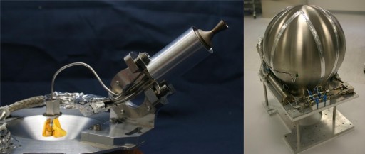
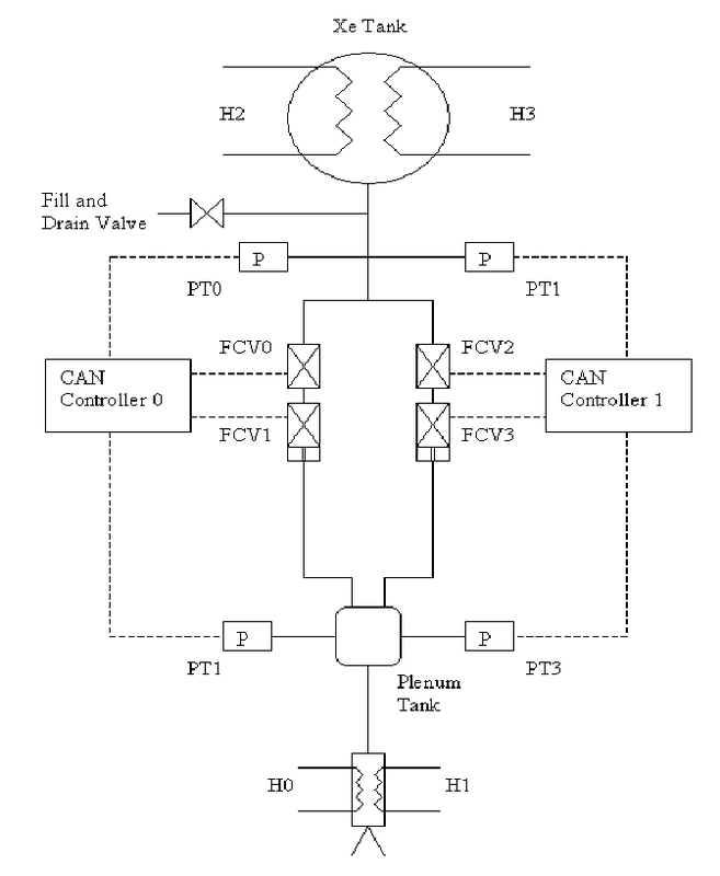
The satellite uses a Hot-Gas Xenon resistojet propulsion system for a total delta-v budget of 36m/s. The system consists of a Xenon tank and resistojet thrusters that delivers a thrust of 10 to 100 Millinewtons operating in blow-down mode with an average impulse of 48 seconds. The 7.4-liter tank can hold up to 12kg Xenon at a pressure of 70 bar. Propulsion will be used for orbit adjustments and drag make-up maneuvers. Overall, the propulsion system weighs 19.4 Kilograms and is 23 by 30 by 30 centimeters in dimensions.
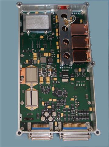
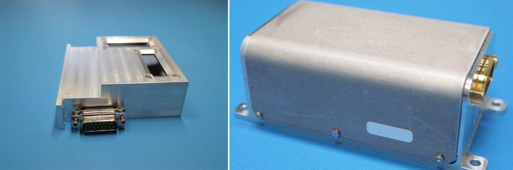
KazEOSat-2 uses an OBC750 onboard computer that is based on a BM PPC750FL processor. The OBS system is in charge of receiving and processing commands from Earth and controlling all satellite subsystems. The system also receives all payload data that is stored and conditioned for downlink by the OBC.
The computer has a memory of 6MB EEPROM (boot software), 256MB EADS, 16MB MRAM and 16MB Flash. It supports the 1553B high-speed data bus as well as two dual CAN buses, eight LVDS inputs and outputs, four opto isolated inputs and four opto isolated outputs. The OBS measures 32 by 32 by 6 centimeters in size and weighs under 2.5 Kilograms requiring 20 Watts of power during operation and 3W in standby.
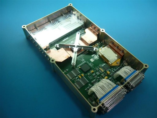
Payload data is stored in a 16GB High-Speed Data Recorder that supports 20 LVDS inputs/outputs at a data rate of 150Mbps, 5 SerDes inputs at up to 2Gbps and 16 LVDS outputs at 150Mbps. The system measures 32 by 17 by 5.5 centimeters at a mass of 1 Kilograms.
Payload data is dowlinked via a X-Band terminal with two dual-axis Antenna Pointing Mechanisms to achieve data rates of up to 160 Mbit/s. The two-axis gimbal mechanism can be used to provide real-time imaging and downlinking capability – keeping the satellite pointed at a target for imaging while the X-Band antenna is locked onto a ground station, downlinking imagery in real time.
The system uses a circularly polarized horn antenna with a narrow-beam width and boresight requiring a high pointing accuracy of one degree. The system supports maximum slew rates of 20deg/s and is capable of focusing the radio frequency output into a high-gain spot-beam that is steered to track the position of the ground station by moving the antenna +/-114.7 degrees in elevation and +/-270 degrees in azimuth.
The X-Band system uses QPSK modulation and achieves an RF power of up to 12 Watts operating at 8.025 to 8.4 GHz. Overall, the antenna gimbaling system is 24 by 19.6 by 18.5 centimeters in size and weighs 2.7 Kilograms while the X-Band transmitter is 21.5 by 20.5 by 13.5 centimeters with a mass of 4 Kilograms.
Command uplink and housekeeping telemetry downlink is accomplished via an S-Band terminal.
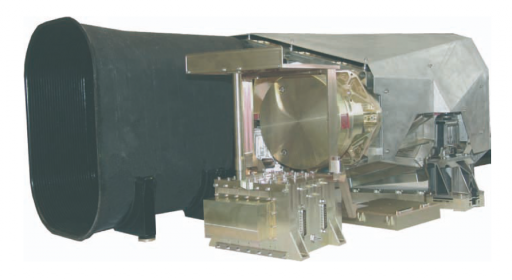
The main payload of the KazEOSat-2 spacecraft is KEIS – the Kazakh Earth Imaging System which consists of an optical imager operating in the visible and near-infrared spectral range. The imager was designed and developed by Jena-Optronik GmbH. KEIS weighs 43 Kilograms, requires a peak power of 93 Watts and consists of two main components: the optical imager (65.6 by 36.1 by 82.4cm) and the Payload Interface Unit (28 by 24.2 by 26cm). The pushbroom imager has a field of view of +/-6.75 degrees about nadir.
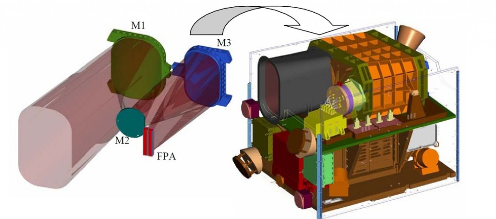
The imaging payload uses a Three Mirror Anastigmatic design that, unlike the conventional Cassegrain or Ritchey-Chrétien systems, provides a larger field of view which is a requirement for the KazEOSat-2 satellite to achieve a wide ground swath. The telescope uses aluminum structures installed on a stable optical payload bench. The KEIS telescope aperture diameter is 145 millimeters allowing light to pass onto the primary, secondary and tertiary mirrors that focus it onto the bandpass filters and detector unit. The optical system uses a folded design without optical obstructions to enable it to take a small volume and keep the aperture small. Overall, the telescope has an effective focal length of 633 millimeters. The mirrors use ultra-precision milling and polishing and a Nickel coating to achieve a a high reflectivity in the visible spectral range.
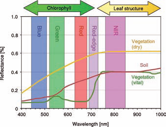
The focal plane assembly uses two CCD packages supplied by e2v, each package consisting of three linear CCD lines containing 12,000 pixels with pixel sizes of 6.5 micrometers. Four CCD outputs are provided per line at a read-out rate of 6.5 MHz. The triple-line CCDs are installed on a ceramic plate and five metal oxide bandpass filters are integrated on filter plates directly installed on the Focal Plane Assembly. KEIS is capable of imaging in five bands – Blue (440-510nm), Green (520-590nm), Red (630-730nm), Red Edge (690-730nm) and Near Infrared (760-850nm). The imagers uses a pushbroom design that scans across the swath as the satellite moves along in its orbit.
To read out each CCD line, dedicated Front End Electronics are used that convert the analog read-out to a 12-Bit digital number that is transmitted to the Payload Interface Unit. The five data inputs from each band are put through a real-time compression before the data can be stored in the mass memory of the satellite. The Payload Interface Unit provides all data handling of imagery acquired by KEIS. Each channel provides the CCD clocks and voltages to the PIU as well as the CCD data to go through analog-to-digital conversions and processing.
After digitization the data is compressed using a lossless scheme and formatted for storage in the HSDR. Data packets that are generated include time stamps and GPS data to put acquired images into context in terms of target location, orbital altitude and time of acquisition. The onboard storage is sufficient for imagery of a 4000-Kilometer long ground pass. For data downlink, science data is put through the Data Formatting Unit that performs CCSDS formatting and encoding before sending the data to the X-Band transmitter.
All payload operations are controlled by the Control and Interface Unit which receives commands from the onboard computer and transmits payload telemetry for downlink via S-Band.
KazEOSat-2 can support three imaging modes – image strip, stereo imaging and mosaic imaging.
For image strip mode, the payload acquires individual image scenes that have a size of 77 by 77 Kilometers that make up a strip when arranged in order. The maximum strip length is 4,000 Kilometers which is useful for mapping. In strip imaging, the satellite can support image acquisition at roll angles of up to 35° off nadir.
The stereo mode produces two images that can be combined to a stereo pair to deliver height information of ground targets. The stereo pair consists of images of the same location taken from different view angles – one image is acquired before the satellite passes a target and the second is taken after the target has passed. In mosaic mode, a series of images are acquired as the satellite passes a target. Unlike the stereo mode, the mosaic mode acquired images of adjacent locations to create a larger image swath.
The ground segment of KazEOSat-2 is operating independently of the ground infrastructure for the KazEOSat-1 mission, but the two systems are located in Astana and are compatible with both satellites to be able to provide redundant systems in case one ground systems is not available. The MRES ground station operates in X- and S-Band for the downlink of payload data and the up/downlink of commands and systems telemetry.
The Mission Control Suite includes equipment from SSTL to provide TT&C functions allowing the customer to command and monitor the spacecraft. Imaging schedules are created by the Information and Extraction Center using the Mission Planning System of SSTL – a software that manages scheduling, resources (power & data), ground station availability, pass geometry and other operational constraints. The Data Processing Center uses data delivered by the spacecraft to generate data products that are then archived.
