
Fengyun-3D Weather Satellite
Fengyun-3 represents the second generation of Polar-Orbiting Environmental Satellites operated by the People’s Republic of China as the low-altitude component of the country’s meteorological and climate satellite system. Satellites in polar orbits build one of two critical segments of an operational weather forecasting and environmental monitoring capability, the other being high-orbiting satellites in Geostationary Orbit that deliver overview data products at fast revisit times to complement the less frequent but more extensive atmospheric readings taken by the polar orbit segment.
The advanced Fengyun-3 satellites host up to a dozen instruments to deliver essential data for meteorologists such as atmospheric profiles and cloud movement as well as data for the scientific community to be used in a number of areas including atmospheric physics and chemistry, climate science and space weather research.
Fengyun (Chinese for ‘Winds and Clouds’) is China’s Meteorological Satellite Program, consisting of at least one operational satellite in Geostationary Orbit and several satellites in polar orbits, creating a satellite constellation to monitor the Chinese and surrounding territory and deliver timely data relevant for weather forecasting and nowcasting. Even numbered Fengyun satellites represent Geostationary spacecraft and odd numbered missions operate from Polar Orbit.
The Fengyun Program saw its first launch back in 1988 when the Fengyun 1A satellite was launched into a Sun-Synchronous Orbit – Fengyun 1B followed in 1990. The development of the Fengyun 2 satellites as the Geostationary component of the constellation started in the 1980s and the high-orbiting segment was inaugurated in 1997 after encountering delays. Seven FY-2 satellites were launched until 2014 and the much-improved three-axis stabilized Fengyun-4 generation debuted in 2016.
Of the FY-1 polar orbiting series, four satellites have been launched with FY-1C making the news in 2007 when it was destroyed as part of an anti-satellite test conducted by the Chinese, creating a large debris cloud in orbit. The FY-1 generation of satellites was succeeded by the FY-3 satellites, the first of which launched in 2008 and was followed by two more in 2010 and 2013 to keep up a steady flow of meteorological data from a Low Earth Orbit, carrying payloads for atmospheric sounding, spectral imaging, radiation monitors, and specialized instruments such as GNSS occultation and ozone sensors.
Fengyun-3 (FY-3) satellites are tasked with six specific mission objectives to a) provide global measurements of three-dimensional temperature and moisture profiles in the atmosphere and deliver cloud and precipitation parameters for numerical weather prediction, b) provide imagery of large-scale meteorological events and biosphere environment anomalies, c) provide geophysical parameters in support of global change and climate monitoring, d) provide global and local meteorological information for specialized services including aeronautical & marine weather forecasting, e) relay environmental data from the ground segment, f) deliver data from a morning- and afternoon orbit.
The Fengyun-3 system has been designed as a two-satellite constellation, one in a morning orbit with a Local Time of Descending Node at 10:00 hours and one satellite in a 14:00 hour afternoon orbit. The operational FY-3 orbit is 836 Kilometers in altitude, inclined 98.75 degrees and has a period of 101.49 minutes with a revisit cycle of six days.

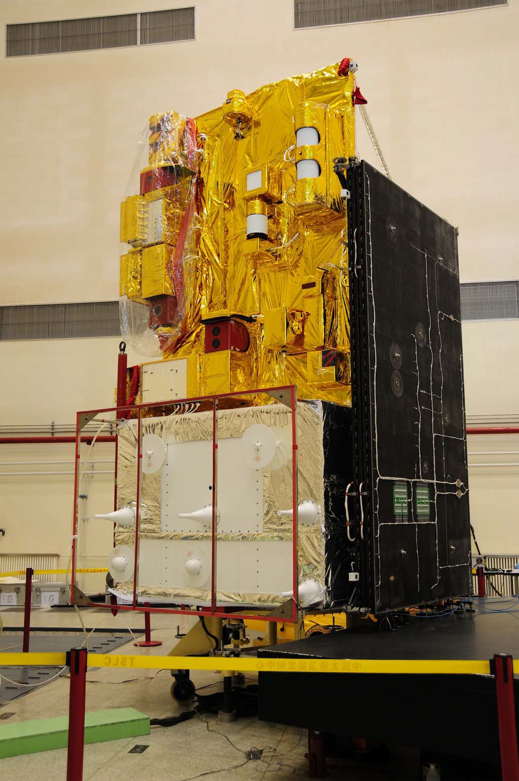
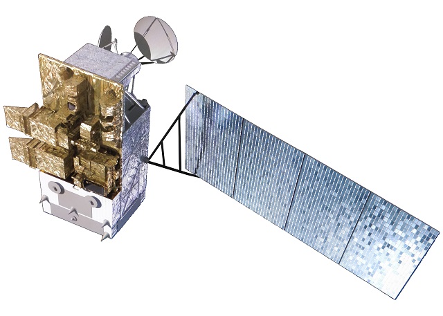
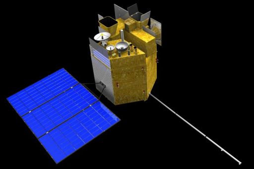
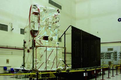
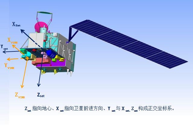
The Fengyun-3 satellites have a launch mass of around 2,400-2,500 Kilograms and use a hexahedral satellite platform developed by the Shanghai Academy of Spaceflight Technology. In launch configuration, FY-3 measures 4.4 by 2.0 by 2.0 in size, growing to 4.46 x 10.0 x 3.79 meters once deploying its single solar array and antenna elements in orbit. The FY-3 structure comprises three principal elements: a Service Module, a Propulsion Module and a Payload Module. Built for a design life of three years and a service life goal of four years, previous FY-3 satellites have regularly outlived their goals; however, some instruments encountered failures before reaching their planned design lives.
The satellite structure employs a central cylinder and guest board for the service and propulsion modules to create the load-carrying structure of the spacecraft with internal baffle plates and truss elements adding stability and creating a separated bay design to hold the various satellite components. The segmented satellite design is also an advantage for thermal control, allowing systems to be naturally decoupled through satellite structure with other thermal control elements primarily relying on passive components (radiators, cold plates, coatings, MLI covers) and active components wherever needed (instrument thermal environment, propellant tank, batteries, etc.)
The FY-3 satellites have a single four-panel solar array for power generation, possessing a total surface area of 22.5 m² and residing on a Solar Array Drive Mechanism that rotates the array to remain in a normal position to the solar vector for maximum power generation. The array has a maximum output power of 2,480 Watts at end of life and an orbit-average power of 1,100 Watts, fed to a pair of 50 Amp-hour Nickel-Cadmium batteries with 36 cells each.

The FY-3 satellites feature a precise three-axis control system relying on Star Trackers as primary attitude determination device, providing orientation solutions accurate to 0.05 degrees. An inertial measurement platform delivers rate measurements to propagate star tracker data in between frames and Earth aspect sensors and coarse sun sensors are used during initial attitude-acquisition and spacecraft safe mode control to ensure stable power generation. Attitude actuation is provided by a redundant set of Reaction Wheels and three magnetic torque rods for momentum unloading from the wheels and safe mode pointing. Overall, the satellite has a pointing accuracy of 0.3 degrees and its attitude stability exceeds 0.004°/s.
GPS is employed for time synchronization and position measurement for geo-tagging of data. Combining GPS data with attitude information allows the satellite to achieve a geo-referencing accuracy of 50 meters.
Operational communications (command uplink and housekeeping telemetry downlink) use an S-Band terminal while instrument data is provided in three different communications modes via L- and X-Band. A direct playback mode known as Delayed Picture Transmission (DRT) delivers stored instrument science data and accompanying engineering data to the NSMC National Ground Playback Stations in Beijing, Guangzhou, Urumuqi, Jamusi and Kiruna with the ladder in view for each orbit of the mission, allowing a fast data pipeline to be kept with a maximum of 96 minutes between data dumps. DRT uses the 8025-8400 MHz frequency band and operates at data rates of up to 110 Mbit/s.
The other two downlink modes, known as Mission Picture Transmission (MPT) and Advanced High Resolution Picture Transmission (AHRPT), provide a continuous broadcast of real-time data collected by the FY-3 satellite that can be received by any equipped ground terminal for real-time implementation in weather monitoring and forecast models. MPT provides the direct broadcast in X-band (7750-7850 MHz) at a data rate of 18.7 Mbit/s including live science and engineering data from the Medium-Resolution Spectral Imager (MERSI). AHRPT provides real time broadcasting of select data in L-Band (1698-1710 MHz) at a lower data rate of 4.2 Mbit/s.

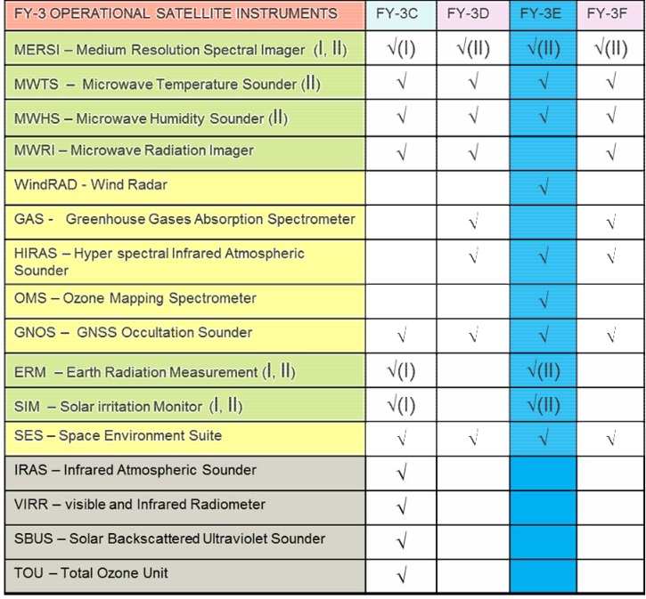
The payload suite of each FY-3 mission varies from satellite to satellite, in part depending on its orbit (AM, PM or Early Morning), the technological readiness of specialized instruments and the specific objectives of each mission (e.g. FY-3E will host a WindRadar for precise measurements of sea surface winds; a specialized FY-RM is in development to collect rainfall measurements.)
Common on all Fengyun-3 satellites is a suite of three Microwave Sounding instruments to collect temperature, humidity and image products, the MERSI Medium-Resolution Spectral Imager for cloud imaging, a GNSS Occultation Sounder capable of delivering atmospheric profiles for temperature, pressure, humidity and space weather, and a Space Environment Suite. These instruments fulfill the most critical objectives of polar-orbiting weather missions – collecting imagery in different spectral bands to follow cloud patterns and assess sea ice/snow cover and microwave sensors for the collection of temperature and moisture information.
The varying elements of the payload suites include additional microwave imagers, spectrometers optimized for greenhouse gases, infrared sensing, Earth radiation & solar irradiation sensors, and sounding / radiometer instruments for visible, infrared and ultraviolet collection as well as specialized total ozone monitors.
Fengyun-3D Instruments
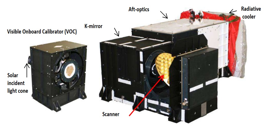
MERSI, the Medium Resolution Spectral Imager, is part of all FY-3 satellites and draws heritage from the Fengyun-1 satellite generation, though featuring a much improved design with additional spectral channels and low-noise performance. Built by the Shanghai Institute of Technical Physics, the scanning instrument comprises a rotating scan mirror assembly, a two-mirror-telescope, three-mirror folding / foreoptics, four focal plane assemblies and support electronics.
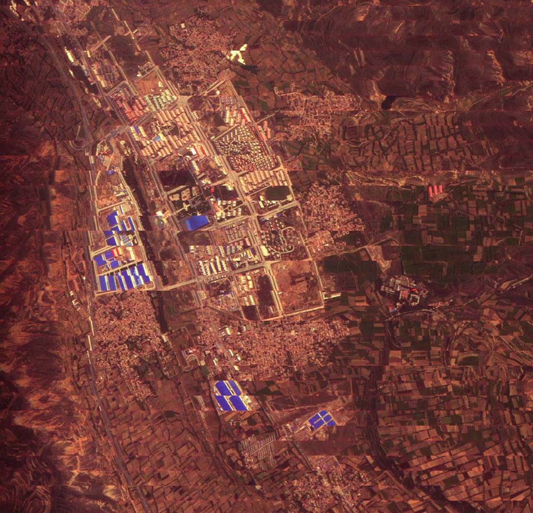
MERSI covers 20 spectral channels from the visible spectrum, though the near and short-wave infrared and into the long-wave infrared range from 0.44 to 12.5 µm. The instrument’s scanning mechanism sweeps out a +/-55.4-degree cross-track swath corresponding to 2,800 Kilometers on the ground, allowing MERSI to cover the entire Earth twice per day. Products delivered by MERSI include diurnal cloud maps, sea and land surface temperature, brine color, land feature, clouds properties, aerosol distribution, and atmospheric water vapor content.
The instrument hosts a Scan Mirror Assembly tilted 45° relative to the optical axis and directing light into the entrance of a 20-centimeter aspherical telescope assembly using a coaxial two-mirror system.
A three-mirror system (called K-mirror) offsets the image rotation from the 45° scan mirror and directs the image to beam-splitting optics that direct the respective wavelength bands to their focal plane assemblies.
MERSI has three Focal Plane Assemblies with four separate detectors for the Visible, Near Infrared, Short-Wave Infrared and Long-Wave Infrared with the SWIR and LWIR facilitated in the same cooled enclosure. The instrument has five high-resolution channels operating at a spatial resolution of 250 meters and hosting 40-element array detectors while the remaining 15 channels feature 10-element linear detectors for a one-Kilometer ground resolution.
The visible and near-infrared focal planes use a new type of photodiode-silicon readout technique that offers a much higher quantum efficiency than heritage systems along with a low-noise readout and exceptional dynamic range that allows collection in a variety of lightning conditions. The SWIR and LWIR focal planes are cooled to 150 and 100 Kelvin using a passive radiative cooler to reduce detector noise. Both bands use Mercury-Cadmium-Telluride detector elements.
MERSI is supported by three electronics boxes, the analog electronics reside in proximity to the detectors for readout and signal amplification; they also set the detector gain and host the focal plane clock. The Main Electronics Module provides instrument power, commanding and processes the analog detector signals into the digital domain for transmission to onboard storage. Calibration of MERSI is provided by views of cold space and a hot reference target on every rotation of the scanning mirror.

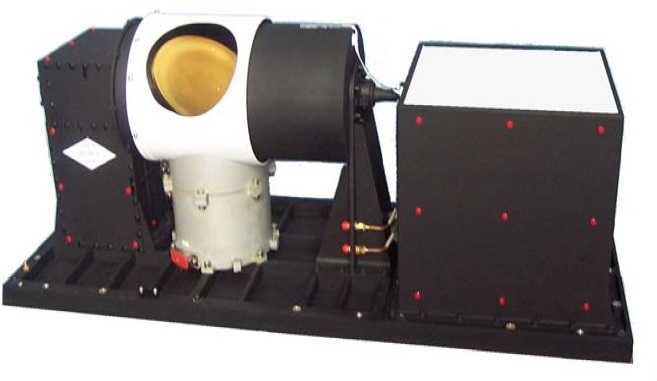
MWRI, the Microwave Radiometer Imager, is a multichannel, conical-scanning microwave radiometer tasked with the collection of all-weather, day-and-night parameters like precipitation, cloud features, soil humidity, sea ice, and atmospheric profiles. It provides polarization-sensitive measurements in ten spectral channels with five frequencies in the range of 10.65 to 89 GHz across a 1,400-Kilometer ground swath and at a spatial resolution of 15 to 85 Kilometers, depending on frequency.
MWRI consists of a large rotating main reflector and an Instrument Support Structure facilitating the RF electronics and sensors as well as the spin mechanism and support systems. The entire instrument assembly weighs 175 Kilograms and requires 125 Watts of electrical power during operation.
As a conical-scanning radiometer, MWRI uses a spinning offset parabolic reflector 97.7 by 89.7 centimeters in size to sweep out a cone-shaped swath on the ground, reflecting natural microwave emissions to four separate feed horns connected to receiver circuits (the 18.7 and 23.8 GHz channels share a feed horn). Hosted within a cylindrical enclosure are the microwave radiometers, digital electronics, mechanical scanning subsystems and support electronics like power supplies and interface units.
The antenna is angled to set up a 44.8-degree incidence and rotates at a speed of 35.3 revolutions per minute, designed to assemble an uninterrupted swath as the satellite moves along in its orbit. The instrument scans a clear viewing sector of over 130 degrees centered on the velocity vector of the spacecraft, the rest of the 360-degree rotation is available for calibration activities.
For an end-to-end calibration of the instrument, MWRI hosts two quasi-optical reflectors 86 and 130 centimeters in diameter to reflect the radiation from a hot calibration load and cold space to the main reflector to provide hot and cold reference targets on every revolution of the main scanning reflector.
MWTS-2, the Microwave Temperature Sounder, is an all-weather, day-and-night microwave sensor for the collection of atmospheric profiles. The second generation of MWTS improves the instrument flown on FY-3A and B by adding nine spectral channels and improving the ground resolution by a factor of two. Data from the instrument is employed to generate atmospheric temperature profiles, determine the freezing level height in clouds, melting layer depth in clouds, and precipitation intensity.
It is a scanning instrument with a field of view of +/-44.5 degrees, corresponding to a swath width of 2,250 Kilometers with the scanning mirror assembly operating in a step-by-step fashion, covering 3.0 degrees per step and reaching a resolution of 32 Kilometers at nadir. MWTS-2 covers 13 spectral bands, including eight high-bandwidth channels between 50.30 and 57.29 GHz and four narrow-band channels around 57.290 GHz with varying bandwidths between 3 and 78 MHz. The instrument achieves a temperature measurement accuracy of 0.75K for most wide-band channels.
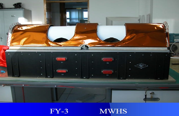
MWHS-2, the Microwave Humidity Sounder, is a four-frequency scanning instrument optimized for atmospheric humidity profile collection. Developed by the Chinese Academy of Sciences/Center for Space Science and Applied Research, the instrument represents an improved version of the original MWHS with ten additional channels and a much improved spatial resolution (41 x 27 km vs. 16 km). Data products delivered by the instrument include total column cloud ice, integrated water vapor, supplementary temperature profile data, cloud ice distribution, precipitation intensity and specific humidity.
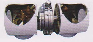
Developed by the Chinese Academy of Science, the 60-Kilogram instrument comprises a receiver unit, power supply unit and electronics assembly. The scan mechanism uses a motor to drive two separate reflectors for the low and high-frequency channels, sweeping out a full revolution every 2.667 seconds during which the reflectors scan a ground swath of +/-53.35 degrees around the spacecraft nadir and also pass cold space and onboard hot targets employed as calibration sources.
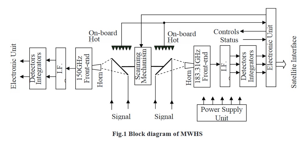
The total power microwave radiometer hosts four heterodyne receiving chains covering fifteen spectral channels: one at 89 GHz, eight at 118.75 GHz with varied bandwidths, one at 150 GHz and five at 183 GHz again with different bandwidths. These spectral channels are optimized for water vapor absorption at different altitudes to deliver the desired humidity profiles, achieving a sensitivity of 1.1 K and an overall accuracy of 1.5 K. The 89 and 150 GHz channels are sensitive for vertical polarization and are referred to as the window channels while the sounding channels use horizontal polarization. The addition of eight channels at 118 GHz is mainly to improve the spatial resolution of samples and boost the instrument’s temperature retrieval capabilities.
The scan motor is driven at variable speed to achieve a constant periodicity for the cross-track scan of 1.71 seconds, passing the cold and hot reference points for 0.1 seconds on each revolution and speeding up while covering the non-scanning portion of the revolution. The sample cells scanned by the instrument are 16 Kilometers in diameter at nadir and the scanning geometry is designed in a compromise to minimize the gaps between successive scans at nadir and also keep the overlap around the edge of the swath minimal. Each 2,600-Kilometer scan includes 98 separate samples taken by the instrument with an integration of 18 milliseconds.
Each receiving chain hosts a feed horn, receiving microwave radiation from the scanning reflectors and transmitting it into a front-end electronics assembly, side band mixer and down-converters and integrators to isolate the bands followed by digitization in the electronics unit. The 118 and 153 GHz window channels have a wider beam enabling a coverage of 32 Kilometers at the sub-satellite point while the remaining channels take 16-Kilometer samples at nadir. Combining the higher-resolution window channels with the sounding channels that carry the information on cloud and temperature profiles can yield a uniform resolution for the instrument.
GNOS, the Global Navigation Satellite System Occultation Sounder, is a radio occultation instrument for remote sensing of Earth’s atmosphere and ionosphere. It uses both the U.S. Global Positioning System and China’s Beidou navigation satellites for occultation measurements, increasing the number of favorable occultations per day.
GNSS occultation for atmospheric and ionospheric measurements is a proven method for the acquisition of temperature, pressure and humidity profiles from high altitude to near-ground level. The science and methodology behind GNSS occultation measurements is well established and has been employed for many scientific projects as well as operational meteorology systems.
GPS operates a constellation of approximately 30 active satellites in six orbital planes, 20,000 Kilometers in altitude, transmitting different L-Band signals used for navigation and precise timing applications as well as a wide variety of other applications including meteorology. At least four satellites are simultaneously visible from any position on Earth, an observer in Low Earth Orbit will usually see 12 satellites at any time.
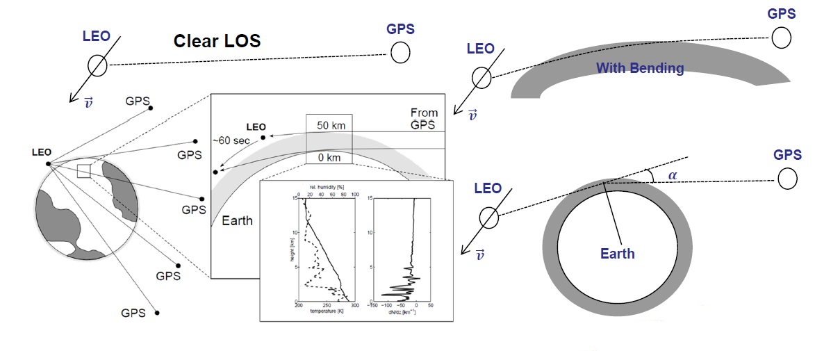
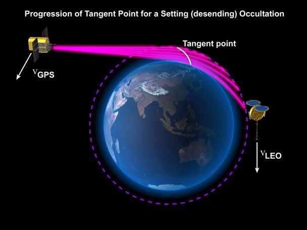
Occultation measurements make use of the fact that Earth’s atmosphere can alter the properties of a GPS signal to extract relevant meteorological parameters. The measurement is done by a satellite that sees its line of sight to a GPS satellite penetrate Earth’s atmosphere as the GPS satellite either rises for sets from the receiver’s vantage point.
Five antennas are part of the GNOS instrument: the PA (Positioning Antenna), the RIOA (Rising Ionosphere Occultation Antenna), the SIOA (Setting Ionosphere Occultation Antenna), the RAOA (Rising Atmosphere Occultation Antenna), and SAOA (Setting Atmosphere Occultation Antenna). These are coupled to three RF units and one central electronics unit where GNSS signals are digitized and transmitted to the spacecraft along with auxiliary data for precise time/position reconstruction.
The Positioning Antenna is a wide beam hemispherical antenna pointing up (zenith) to track up to six Beidou and eight GPS satellites at the same time to provide positioning measurements and orbit determination as well as a time synchronization for all instrument systems.

The RIOA and RAOA face toward the anti-velocity vector (rear) and the SIOA and SAOA face forward with each possessing the ability to track up to four Beidou and six GPS occultations. The atmosphere antennas are optimized for wide azimuth and narrow elevation tracking (+/-35° on azimuth and +/-7.5° on elevation) to cover the atmosphere from ground level up into the tenuous atmospheric layers for the collection of pressure, humidity and temperature profiles. The ionosphere antennas have a wider elevation coverage to measure ionospheric properties like total column electron content between the satellite and the navigation signal source.
The 14-Kilogram GNOS instrument tracks the GPS L1 and L2 frequencies as well as the B1 and B2 bands of Beidou, receiving around 500 favorable GPS occultations and 200 Beidou occultations per day. GNSS phase shift data from the instrument is processed into atmospheric profiles with each occultation covering around 300 Kilometers in the horizontal direction with vertical layers of 0.5 Kilometers to obtain high-resolution vertical profiles.

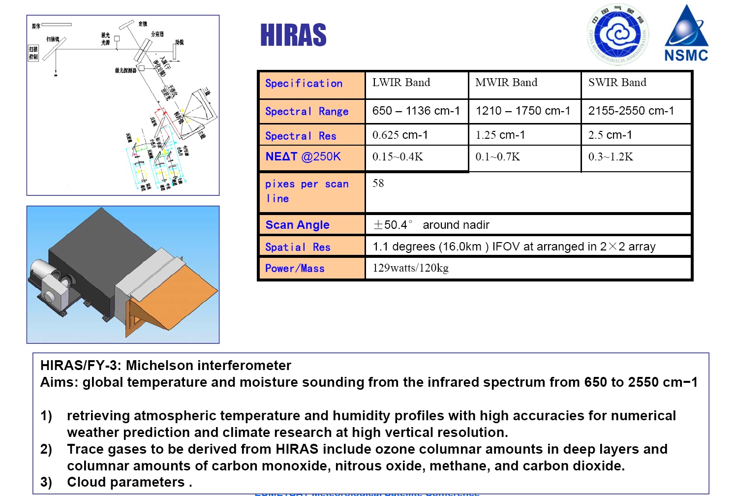
HIRAS, the Hyperspectral Infrared Atmospheric Sounder, is a cross-track scanner coupled to a Michelsen Interferometer to obtain high-resolution infrared spectra to refine atmospheric profiles for temperature and humidity plus measurement of ozone profiles and total column greenhouse gases. Similar to the CrIS instrument on NOAA’s JPSS satellites, HIRAS has become a powerful tool for more accurate, detailed atmospheric observation which, when combined with microwave soundings, yields much improved short-term weather nowcasting and longer-term forecasting in the three to seven-day range.
The interferometer uses a standard plane-mirror Michelsen configuration in which incoming light is split with a beam splitter device onto two optical paths created by flat mirror systems with one path at constant length and the other varied by moving the mirror to create an interference pattern on the detector that is dependent on the path difference which is precisely known through accurate measurement of the moving mirror position.
An interferogram is created by taking measurements of the signal at many discrete positions of the moving mirror. Fourier transformation then converts the interferogram into a high-resolution spectrum (with resolution depending on the number of discrete measurements).
The major advantage of Fourier Transform Spectrometry over dispersive spectrometers (grating or prism spectrometers) is a higher spectral resolution and much improved signal to noise ratio since the interferometer’s detector effectively monitors all wavelengths simultaneously throughout the measurement as opposed to grating spectrometers where the measured wavelength varies across the detector.
The 120-Kilogram instrument covers a total of 1,370 spectral channels and a ground swath of 2,250 Kilometers by rotating its scanning mechanism and taking 58 samples per scan line, arranged in 2 x 2 arrays with a spatial resolution of 16 Kilometers. HIRAS covers three spectral bands: 3.92-4.64µm (2.5cm-1 resolution), 5.71-8.26µm (1.25cm-1) and 8.80-15.39µm (0.625cm-1).
GAS, the Greenhouse-gases Absorption Spectrometer, is a grating spectrometer that operates in four visible and near infrared channels at 750-770 nanometers, 1.56-1.72 µm, 1.92-2.08 µm and 2.20-2.38 µm to collect measurements of atmospheric composition.
The instrument is sensitive for relevant greenhouse gases: Carbon Dioxide, Methane, Carbon Monoxide and Nitrous Oxide. The VIS/NIR channel of the instrument can also be used for cloud top height measurements around 760nm.
GAS has two fields of view, one pointed nadir and the other for sunglint observations to collect vertical data. Sample cells of 100 Kilometer side length are measured with a spatial resolution of 10 Kilometers at spacecraft nadir, delivering global greenhouse gas maps at a refresh rate of one per month.
The Space Weather Suite installed on Fengyun-3 comprises four individual instruments: the Ionospheric PhotoMeter IPM, the High Energy Particle Detector HEPD, the Ionosphere Measurement Sensor IMS, and the Wide-field Auroral Imager WAI.
IPM is an X-Ray Spectrometer to collect X-ray spectra for an energy range of 3 to 100 keV at a spatial resolution of 80 Kilometers, providing X-ray flux spectra and X-ray sky images directed toward Earth’s limb. The HEPD instrument is tasked with the measurement of charged particles – electrons at energies of 0.25 to 2.0 MeV, protons at 6.4 to 38 MeV and alpha particles from 15 to 60 MeV.
IMS measures ionospheric electron temperature and density as well as platform charge and radiation dose via a set of Langmuir Probes. Langmuir probes can determine electron temperature, electron densities and the electric potential of a plasma. Two or more electrodes are inserted into a plasma environment with a constant or time-varying electric potential between them to allow the determination of physical plasma properties by measuring currents and potentials in this electrode system. A bias voltage is applied to the probe and the resulting current that is measured is proportional to plasma charge density.
WAI is an auroral observation instrument hosting a fluxmeter for visible wavelengths of 428 to 630 nanometers and a UV imaging spectrometer that includes the prominent Lyman-Alpha line of Hydrogen at 121.6nm. The instrument is directed toward the limb and collects UV samples every 22 and VIS measurements every 180 seconds to deliver UV flux spectra, electron density, ionospheric plasma density and auroral measurements.
