
DMSP – Block 5D-3 Spacecraft Overview

The Defense Meteorological Satellite Program (DMSP) is operated by the US Air Force Space Command and the National Oceanic and Atmospheric Administration to provide meteorological, oceanographic, and solar-geophysical data including infrared, and passive microwave sensor data in support of global Department of Defense (DoD), Department of Commerce (DoC), and National Aeronautics and Space Administration (NASA) operations.
Lockheed Martin is the manufacturer of the current generation of DMSP satellites as the program looks back at a long history spanning more than five decades.
The program was initiated in the early 1960s as a highly classified military program running alongside the civil meteorology satellite program. Launching its first satellite in 1962, DMSP had the initial purpose of delivering weather and climate data for use by the military for more effective operations.
One important aspect of the early DMSP application was the forecasting of cloud covers to enable CORONA optical reconnaissance satellites to acquire images of locations when no cloud cover was present as the onboard film supply of the CORONA satellites was limited. DMSP data was also relayed to deployed forces in order to allow improved tactical planning.
The project was declassified in 1972 and DMSP data was made available to the public. In 1994, a tri-agency organization was formed between DoD, DoC, and NASA to develop a National Polar Orbiting Environmental Satellite System (NPOESS) to meet the needs of all three agencies while converging the existing polar-orbiting weather satellite program and DMSP. NOAA was handed control, maintenance & operation responsibility of the DMSP satellites in 1998 while the Air Force continued the development and acquisition of DMSP systems.
In 2010, the NPOESS program was terminated – being split into the civilian NOAA/NASA operated JPSS (Joint Polar Satellite System) and the military DWSS (Defense Weather Satellite System). Both programs will share data and ground segment operations. Data from European MetOp Satellites will also be used by the future programs.
Starting out in the early 60, the program started out as Defense System Applications Program (DSAP) and the Defense Acquisition and Processing Program (DAPP). The project was also known under the code name Project 35, or P35.
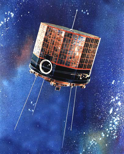
The first DMSP satellite generation, known as Block 1, saw 11 launches from 1962 to 1965, seven of which reached orbit. These small spin-stabilized satellites were small spacecraft weighing just 50 to 90 Kilograms, limited to the launch vehicles available at the time. Block 1 satellites carried a shutter-style TV camera to acquire cloud-cover imagery in visible light. The P35 satellites were the first spacecraft to demonstrate the Sun Synchronous orbit, laying the foundation for many future operational satellite programs.
Three second generation satellites, weighing about 73 Kilograms, were launched in 1965 and 66, two reached orbit. A single Block 3 satellite was launched in 1965 to provide tactical access to weather data from a readout station in Vietnam. Ten Block 4A satellites were launched from 1965 to 1967 before the fifth generation of satellites was inaugurated.
These Block 4 spacecraft were equipped with two vidicon cameras for collecting high-resolution video imagery for downlink to provide information on current cloud conditions. These sensors had a resolution as high as 4 Kilometers at the center of the image and about 16km at the edge of the frame. Block 4 spacecraft also demonstrated the use of infrared sensors allowing the first attempts of combining reflected and emitted energy data to analyze cloud patterns.
DMSP Block 5A & 5B

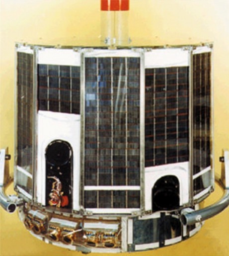
Six Block 5A satellites were delivered to orbit from 1968 to 1971 each weighing 420 Kilograms. Block 5A satellites employed three-axis stabilization and inaugurated the Operational Linescan System as well as a radiometer payload and a low-light amplification system. The Block 5B satellite generation saw five launches until 1974 with each spacecraft weighing 510 Kilograms and incorporating improvements in optics technology and signal processing. Three Block 5C satellites launched until 1976, one failed to reach the correct orbit.
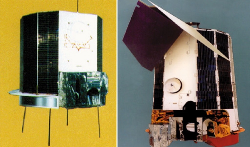
The current Block 5D-3 constellation was preceded by two earlier versions of the 5D satellites – five D-1 satellites carrying different payloads were launched until 1980 before the more advanced 5D-2 satellites became available in 1982 – each carrying five to seven instruments. The first 5D-3 satellite launched in 1999 with six 5D-2 instruments to test the new satellite bus followed by the F16 satellite in 2003 with the new 5D-3 payload. Since F16, all 5D-3 satellites have been carrying the same payloads.
DMSP 5D-3 satellites operate in Sun Synchronous Orbits at an inclination of 98.9 degrees and an operational altitude range of 811 to 853 Kilometers with a nominal altitude of 833 Kilometers. Two DMSP satellites are part of the operational constellation.
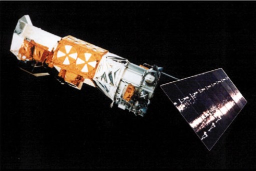
DMSP Block 5D-3 satellites weigh about 1,230 Kilograms and use Lockheed Martin’s Tiros N satellite platform. The spacecraft measure 1.2 meters in diameter and 6.4 meters in length once deployed in orbit. 5D-3 satellites consist of several sections – a precision mounting platform that hosts optical payload equipment that requires precise alignment, an equipment support module that includes satellite bus systems and a payload module that accommodates the meteorological sensors.
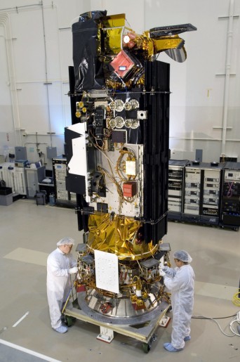
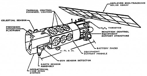
A deployable solar array featuring ten solar panels is installed on a boom that can be used to move the single solar array in order to track the sun and optimize power generation. The 9.29m² array delivers 2,200 Watts of electrical power that is stored in batteries and distributed to the various satellite systems and payloads.
Attitude determination and control is provided by a suite of systems installed on the satellite. Star trackers, sun sensors, an inertial measurement unit and an updated ephemeris navigation system provide accurate three-axis attitude data to the satellite’s control system. Attitude actuation is accomplished by a reaction wheel assembly and magnetic torquers. Overall, the spacecraft has a pointing accuracy of 0.01 degrees allowing it to accurately point its instruments to Earth. In backup mode, the ADCS can still function with an accuracy of 0.12 degrees.
DMSP uses Solid State Recorders to store acquired instrument data and housekeeping telemetry. Downlink of instrument data is available in real time or in stored mode. DMSP uses two S-Band downlink frequencies to transmit its instrument data. For real time tactical transmissions, data rates of 1.024 Mbps are achieved while stored data is transmitted at 2.66 Mbps to four ground stations. UHF downlink can also be supported. All DMSP downlinks are encrypted. Command uplink is accomplished via L-Band at 2Kbps and is only needed for periodic servicing operations as the DMSP satellites are built to carry out their mission autonomously. Downlinked data is relayed at 3.072 Mbps via commercial geostationary communications satellite to the Air Force Global Weather Central for processing and distribution.
DMSP F19 carries the following instruments:
- OLS (Operational Linescan System)
- SSMIS (Special Sensor Microwave Imager & Sounder)
- SSULI (Special Sensor Ultraviolet Limb Imager)
- SSUSI (Special Sensor Ultraviolet Spectrographic Image)
- SSI/ES-3 (Special Sensor Ionospheric Plasma Drift/Scintillation Monitor)
- SSJ/5 (Precipitation Electron/Proton Spectrometer)
- SSF (Laser Threat Warning Sensor)
- SSM (Special Sensor Magnetometer)
OLS (Operational Linescan System
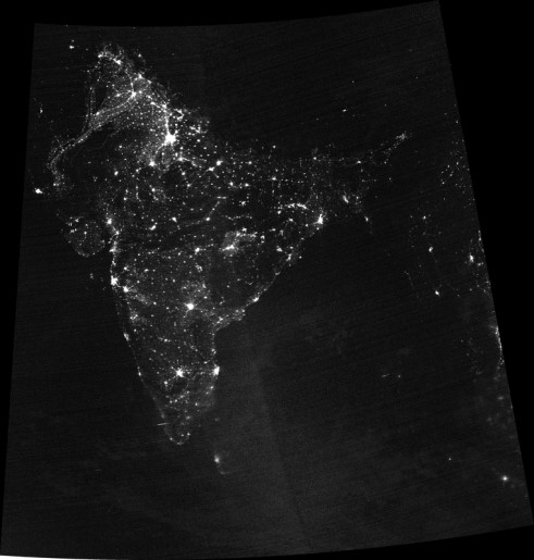
The primary sensor of the DMSP satellite is OLS – the Operational Linescan System, built by Northrop Grumman to deliver day and night cloud cover imaging. The instrument consists of two telescopes and a photomultiplier tube along with different detectors to provide imagery in the visible spectrum and the infrared spectral range.
The OLS imaging telescope uses a Cassegrain design with a 20.3 centimeter aperture creating a 185cm² collecting area and a 122-centimeter effective focal length (using a primary concave mirror and a secondary convex mirror aligned about the optical axis to focus light on the detector). The telescope has a scan angle of +/-56.25 degrees creating a swath width of 2,960 Kilometers. Light collected by the telescope is split to two channels by a beam splitter. The two optical paths use optics to direct the light to the respective visible and infrared detectors and to the photomultiplier tube. OLS uses a flying spot whiskbroom design as its detector sweeping back and forth to cover the ground swath.
OSL’s visible channel covers a wavelength range of 0.4 – 1.1 µm using a silicon photoconductive diode. The VIS detector is divided into three segments to provide a nearly constant resolution across the swath, utilizing two smaller segments to cover the outmost portion of the swath at scan angles of more than 41 degrees. The channels can support a large range of illumination and constantly adjusts its gain across an image to compensate for differences in solar illumination particularly over the terminator region.
This is achieved by the implementation of a switchable gain amplifier regulated by a digital processor that uses scan angle and solar geometry data to control the instrument gain. To avoid saturation on the visible detectors, OSL uses a series of sun shades, low-scatter surfaces and aperture stops.
The infrared channel of the OSL instrument uses a two segment HgCdTe photoconductive detector that operates at a temperature of 108K provided by a cone cooler. The two segments are used on the far sides of the swath with scan angles of over 41 degrees, they are summed over the central portion of the swath. The channel covers a spectral range of 10.0 – 13.4 µm achieving a ground resolution of 0.56 Kilometers across the swath.
The multiple dynode photomultiplier tube uses a GaAs opaque photocathode to acquire visible imagery (0.47 – 0.95 µm) at night optimized to detect low-light targets down to extremely low radiances. The sensor provides imagery at a spatial resolution of 2.7 Kilometers. The light intensification provided by the PMT allows the observation of faint visible- near infrared emissions such as towns, villages, gas flares, boats and fires. Fire detection is the primary objective of the PMT that is capable to pick up medium sized agricultural fires up to large forest fires. Ground and cloud imaging under lunar illumination down to a quartermoon is also supported by PMT.
OLS data can be downlinked as high-resolution imagery that is acquired by the instrument or onboard processing can be employed involving a smoothing (averaging) algorithm to reduce the data rate by a factor of 25 by electronically smoothing the cross-track pixels and digitally averaging of the along-track direction. Smoothing is employed when required due to bandwidth or recorder limitations.
SSMIS – Special Sensor Microwave Imager & Sounder
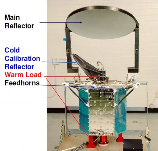
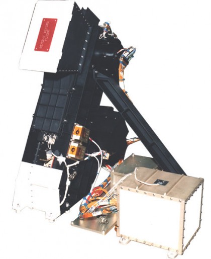
SSMIS – the Special Sensor Microwave Imager & Sounder combines the capabilities of several heritage sensors into a single multichannel, conical-scanning microwave radiometer. The instrument uses 24 channels to gather radiometric brightness data across a wide ground swath to deliver data on atmospheric, oceanographic and selected land parameters on a global scale including cloud structure, sea surface winds, rain rates, cloud water, precipitation, soil moisture, etc. The instrument is built by the Aerojet Corporation of Azusa, CA.
SSMIS consists of a large rotating main reflector and an Instrument Support Structure facilitating the RF electronics and sensors as well as the spin mechanism and support systems. The instrument weighs 96 Kilograms, requires 135 Watts of power and a data rate of 14.2kbit/s.
The sounder uses a conical scan geometry. The off-nadir angle that defines the cone swept out by the imager is 45 degrees which creates an Earth Incidence Angle of 53.1 degrees with a wide ground swath of 1,700 Kilometers. The instrument scans a clear viewing sector of 144 degrees centered on the velocity vector of the spacecraft. The rest of each 360-degree revolution is used for calibration operations. For morning ascending node spacecraft, the instrument observes an area aft of spacecraft nadir while morning descending node spacecraft have SSMIS scanning an area forward of nadir. The scanning geometry allows a constant horizontal spatial resolution and polarization across the entire ground swath.
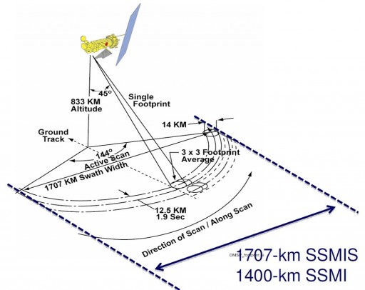
The parabolic reflector rotates along the vertical axis of the instrument at 32 revolutions per minute. It is inclined at approximately 23º to the horizontal. SSMIS uses a 61-centimeter antenna and beam width from 0.4 to 1.9 degrees. The instrument covers a total of 24 channels with frequencies of 19.35 GHz to 183.31 GHz to retrieve temperature and moisture profiles from ground level up to an altitude of 80 Kilometers. The footprint sizes vary with the frequency of the individual channels. The lower frequencies have large footprints that have sufficient overlap in the along-scan direction to achieve a continuous and complete coverage. The high-frequency channels no longer have overlap from one scan to the next causing gaps in coverage, however, the minimum coverage requirement is maintained with the IFOVs of these channels.
Instrument Calibration is accomplished by a cold sky target and a hot load that are being scanned as part of the 256-degree calibration cycle of each instrument rotation. The cold sky target is a reflector targeted at space to provide the coldest possible target for calibration purposes.
The hot load uses a design that minimizes thermal gradients to provide a high stability. Three thermistors are used to precisely measure the current state of the hot load at each scan with special focus on possible spatial and temporal variations even on small scales.
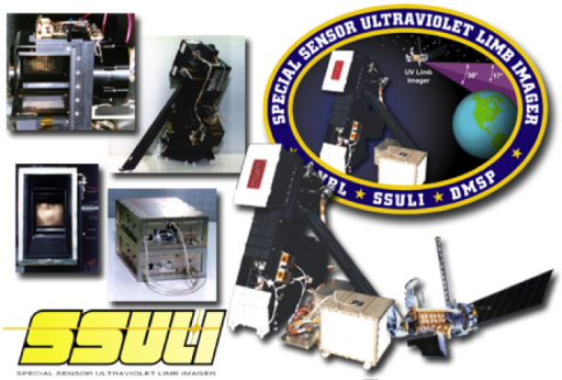
SSULI – Special Sensor Ultraviolet Limb Imager
SSULI, the ultraviolet limb imager has been designed at the Naval Research Laboratory and is an optical spectrograph that measures the extreme and far ultraviolet radiation from the Earth’s limb creating high-resolution (spatial and spectral) vertical altitude profiles of the atmosphere. SSULI is installed on the +X panel of the DMSP satellite and covers a spectral range of 80 to 170 nanometers.
The instrument uses a common spectrometer design. Light enters the instrument via a flat scan mirror that can be moved to allow the instrument to scan from 10° to 27° below the satellite horizon in its nominal scanning mode and from 10° to 40° in secondary mode. Light from the scan mirror is directed through a telescope and to a collimator and the spectrograph entrance slit.
Light entering the entrance slit is dispersed by an optical grating and focused onto the detector assembly. The Instrument has an instantaneous field of view of 0.15 by 2.4 degrees and a field of regard of 30 by 2.4 degrees as the scan mirror goes through its full range of motion. SSULI achieves a spectral resolution of 1.5 nanometers across its spectral range.
The detector assembly uses an imaging microplate detector with a wedge and strip anode to characterize photon events. SSULI is capable of detecting extremely low intensities by registering individual photons in the focal plane’s wedge and strip microchannel plate detectors. SSULI can register 0.5 counts per second per Rayleigh at the 83.4nm wavelength. Detector and control electronics process the signals from the detector and transfer acquired data, and control all of the instrument functions including the motion of the scan mirror.
The scanning mirror sweeps the field of view across the limb of Earth to vertically scan the atmosphere and obtain vertical profiles of the natural airglow radiation caused by atomic oxygen and nitrogen, molecular nitrogen and other species including ions in the upper atmosphere and ionosphere.
The vertical scan profile covers altitudes from 50 to 750 Kilometers at a scan cadence of 90 seconds. The scan rate is faster at high tangent altitudes and is automatically slowed down at lower altitudes that typically show more structure in the airglow.
SSULI delivers electron and density profiles and ion and neutral densities from 50 to 750 Kilometers.
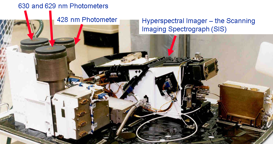
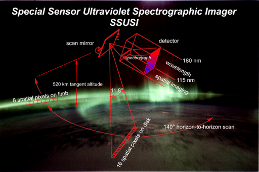
SSUSI – Special Sensor Ultraviolet Spectrographic Imager
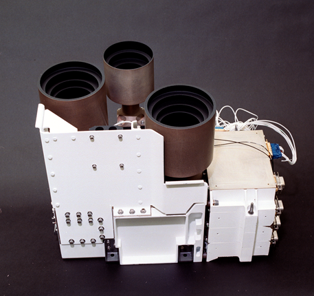
SSUSI – the Special Sensor Ultraviolet Spectrographic Imager consists of a Scanning Imaging Spectrometer and a Nadir-looking Photometer System. The instrument was developed by the Applied Physics Laboratory, JHU. It is used to observe the nightglow and nightside aurora in visible and ultraviolet radiation to provide electron density profiles, neutral density profiles, auroral energy deposition rate and auroral oval location. These data products are important for space weather monitoring and prediction.
The Scanning Imaging Spectrometer SIS uses a cross-track scanning mirror at the input to a folded telescope and spectrograph optics. Light from the scanning mirror is directed into the 11.8-degree FOV telescope that focuses the light at a focal length of 75 millimeters and passes it onto the spectrograph entrance slit using a telescope mirror. Using optics, the light is collimated and passed onto a toroidal grating before the light is refocused and reaches the detector. The optical path incorporates baffles to prevent stray light from reaching the focal plane at the slit and the detector.
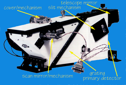
SIS uses a two-dimensional photon-counting detector with 16 pixels in the along-track direction and 160 pixels in the cross-track direction. Position sensitive anodes are used to determine the direction of incoming photons. The scan mirror sweeps the 16-pixel footprint to produce one frame every 22 seconds. The instrument can be operated in imaging mode and spectrograph mode.
In the imaging mode, SIS performs simultaneous measurements at five wavelengths from 115 to 180 nanometers. The imaging scan sequence features a limb-viewing section from -72.8° to -63.2° from nadir followed by a nadir viewing section from –63.2° to 61.6°. The limb scanning section consists of 24 cross track pixels by 8 along track pixels at five wavelengths achieving a cross-track resolution of 0.4°. The nadir viewing sequence has a cross track resolution of 0.8° per pixel, and always contains 16 along track pixels and five colors. For imaging, SIS has an instantaneous field of view of 0.3 by 11.84 degrees or 0.74 by 11.84 degrees using a wider entrance slit. With the scanning mirror operating, SIS scans a field of view of 9.6 cross-track in limb-imaging mode and 125 degrees in nadir-viewing mode. Overall, SIS images have a spatial resolution of 10 by 10 Kilometers and a spectral resolution from 1.2 to 4.2 nanometers.
In Spectrograph mode, SIS holds its scanning mirror at a fixed viewing angle and achieves a spatial resolution of 2.3 by 20 Kilometers and a spectral resolution of 1.2 nanometers. The imaging spectrograph uses three slits of different widths using motors to switch in between the different slits. The narrowest slit is used for spectrographic observations.
The imaging spectrograph includes two redundant detectors that are selected by a pop-up mirror which slightly reduces the sensitivity of the instrument due to the extra reflection. The detector features a microchannel plate intensifier with a wedge and strip anode. The detector is 25mm in diameter using a Z-stack MCP arrangement with Cesium Iodide deposited on the MCP front surface.
The Nadir-looking Photometer System NPS consists of three individual nadir-looking photometers that operate at visible wavelengths of 427.8, 629.4 and 630 nanometers.
NPS is only used at night and provides the height of the F-region ionosphere and to corroborate the characteristic energy and flux of precipitating electrons in the aurora. The instrument requires two detectors at 630nm to make corrections for the Earth albedo and backscattered moonlight and starlight.
Each of the three photometer units includes an integrated detector package consisting of a photomultiplier tube, high voltage power supply, and pulse amplitude discriminator electronics.
The 427.8nm photometer has a spectral bandwidth of 5nm and a pixel field of view of 2 degrees using a 1.27cm optics diameter and 1-second pixel integration time. It uses a Bi Alkali detector with photocathodes that are 7mm in diameter. The other two channels use Tri-Alkali detectors and operate at spectral bandwidths of 0.3nm. NPS creates images with a spatial resolution of 25 Kilometers.
Each photometer uses interference filters in front of the collimator lens. The filters are kept at precise temperatures using a thermostatically controlled heater unit for the bandpass to remain constant and controllable. The detectors are kept at –20 to –30°C to reduce the dark current.
SSI/ES-3 – Special Sensor Ionospheric Plasma Drift/Scintillation Monitor
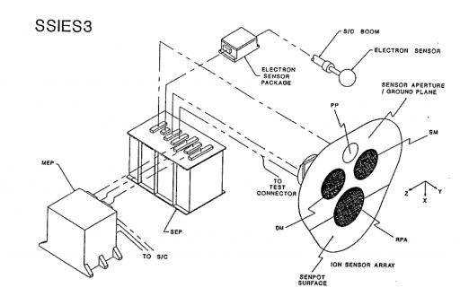
The SSI/ES-3 thermal plasma instrument is a space environment monitor that measures ambient electron density and temperatures, the ambient ion density, and ion temperature and molecular weight. The SSI/ES-3 sensors are installed on a boom and include a Langmuir Probe and a Retarding Potential Analyzer as well as an Ion Drift Meter, a Plasma Probe, a Total Ion Trap, a Sensor Potential Control System and associated sensor electronics.
All of the ion sensors use a Faraday Cup Design using planar apertures and planar collectors with all sensors facing the spacecraft velocity vector at all times. The sensors measure hydrogen, helium and oxygen ions and the ions’ bulk motion relative to Earth’s surface. The ions pass through a series of flat screens with applied electrostatic potentials before hitting a flat metal plate that collects them. Impacting ions cause a distinct current that is detected and recorded. Unwanted particles are rejected by charged wire mesh screens that are located between the aperture and collector.
Langmuir probes can determine electron temperature, electron densities and the electric potential of a plasma. Two electrodes are inserted into a plasma environment. The electrodes have a constant or time-varying electric potential between them to allow the determination of physical plasma properties by measuring currents and potentials in this two-electrode system. The probes are stepped through a short sweep cycle from –6V to +4V to create the voltage-current profiles.
SSJ/5 – Precipitation Electron/Proton Spectrometer
The SSJ/5 precipitating particle spectrometer is a spherical electrostatic analyzer developed by Amptek Inc. that measures electrons and ions in an energy range of 0.03 to 30 kilo electronvolts. Precipitating electrons and ions are an important source of production of ionospheric plasma in the auroral oval region and are capable of modifying the conductivity of the auroral ionosphere.
The instrument uses a a nested spherical deflection plate system to simultaneously analyze electrons and ions over a field of view of 8° by 90°. The sensor assembly is 15 by 15 by 23 centimeters in size weighing 3.2 Kilograms. It uses a space qualified microprocessor that permits customizing data rates, measurement ranges, on board storage, and specific analysis algorithms, such as Auroral boundary detection or real time charging measurements.
Special Sensor Magnetometer
The Special Sensor Magnetometer SSM is a triaxial fluxgate magnetometer built by NASA Goddard Spaceflight Center. The instrument is installed on a 5-meter boom to reduce spacecraft noise. SSM measures geomagnetic fluctuations caused by solar geophysical phenomena. In combination with the other DMSP instruments, SSM delivers heating and electron density profiles in the high-latitude ionosphere. The fluxgate sensor uses the nonlinearity of magnetization properties for the high permeability of easily saturated ferromagnetic alloys to serve as an indicator for the local field strength.
The three axes of the SSM instrument are aligned with the spacecraft axes with an alignment accuracy of 0.5 degrees.
(the X-axis is downward, aligned with spacecraft vertical; the Y-axis is parallel to the spacecraft velocity vector and the Z-axis is away from the solar panel and anti-parallel to the orbit normal vector).
Post-launch calibration can determine the mis-alignment between the instrument axes and the spacecraft axes to an accuracy of 0.1 degree/axis or better.
SSM covers a range of ±65535 nano Tesla with a resolution of 2nT and a sensitivity of under 50nT. The instrument takes 12 readings per second. The magnetic field from electrical currents flowing in the ionosphere and magnetosphere is determined by measuring the overall magnetic field and subtracting the magnetic field from the solid earth from the data and making corrections for the influence of the spacecraft magnetic field.
Laser Threat Warning Sensor
The Laser Threat Warning Sensor is a static Earth-viewing laser warning sensor built by Sandia National Laboratory. Details on the instrument are not available.
Ground Segment
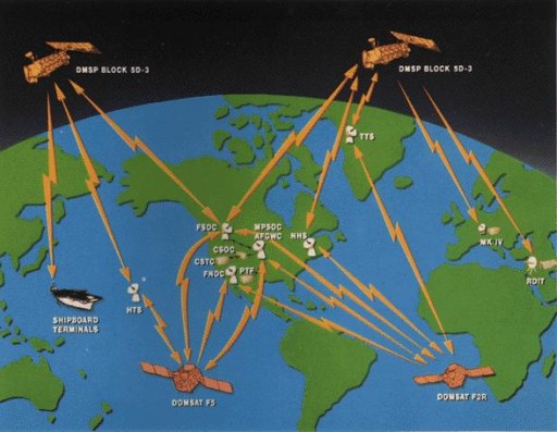
The Satellite Operational Control Center in Suitland, MD is the primary operations center for DMSP in charge of launch support, early orbit operations and commissioning and day-to-day satellite operations. The Integrated Polar Acquisition and Control Subsystem is used for DMSP satellite telemetry processing and spacecraft commanding as well as ground system configuration.
Three US Air Force and one NOAA ground stations are used to downlink stored data from the DMSP spacecraft: the NOAA Fairbanks Tracking Station, the Hawaii Tracking Station, the New Hampshire Station and the Thule Tracking Station (Greenland).
Tactical Terminals that can be deployed in any given location on Earth can receive DMSP data in real time. Also part of the DMSP user segment are the Air Force Global Weather Central and the Navy Fleet Numerical Meteorology Oceanography Center.
