
PSLV C37 CubeSats
PEASSS

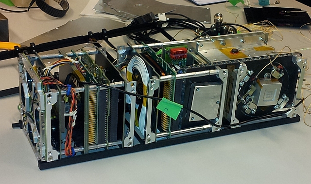
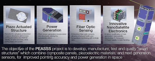
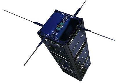
PEASSS is the Piezoelectric Assisted Smart Satellite Structure, a 3U CubeSat developed by a European Consortium led by Dutch nonprofit science company TNO.
Managed under the framework of a European Commission CORDIS Project, PEASSS aims to demonstrate a small satellite comprised of ‘smart structures’ which combine composite panels, piezoelectric materials and next-generation sensors for a vastly improved satellite system. PEASSS tests out nano electronics, a piezo power generation system, a piezo-actuated structure, a fiber-optic sensor and an interrogator system.
Application of technology tested on PEASSS will provide a significant improvement for virtually all Earth Observation sensor platforms through improved pointing accuracy and stability as well as a reduction of mechanical noise within the satellite structure.
Funding for PEASSS is provided by the European Commission under the Seventh Framework Program and the project consortium consists of TNO, with NSL, AST, Technion, SONACA and ISIS – Innovative Solutions In Space.
Piezoelectric technology can build the basis for sensors, actuators and energy harvesters with advantages over traditional systems that currently represent the state of the art in spaceflight technology. Despite numerous advantages, application of piezoelectric systems has yet to find its way into space flight, at least beyond conceptual design stages. PEASSS introduces piezoelectric systems for both, active actuation and measurement of the actuator performance.
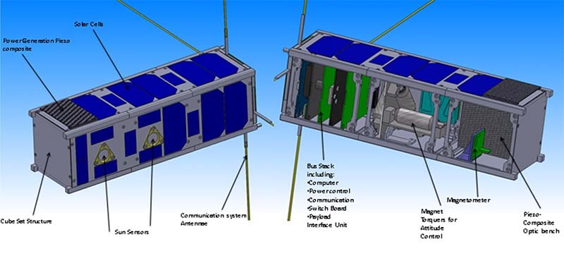
The smart structure aspect of PEASSS is realized by embedding piezo-electric actuators into the satellite structure to be able to move panels and structural elements of the satellite with very high accuracy in order to keep optical systems in perfect alignment in changing thermal environments. A system of this kind with moving parts that respond to thermal expansion/contraction is much lighter than massive optical benches built to be as stiff as possible in changing temperatures. Furthermore, smart panels can also be used to cancel out acoustic noise and vibration from the satellite system, enhancing data products collected by various imaging systems.
Power generation through piezoelectric systems utilizes the pyroelectric effect and could yield further mass and volume savings on future satellites by incorporating power generation systems into the satellite structure.
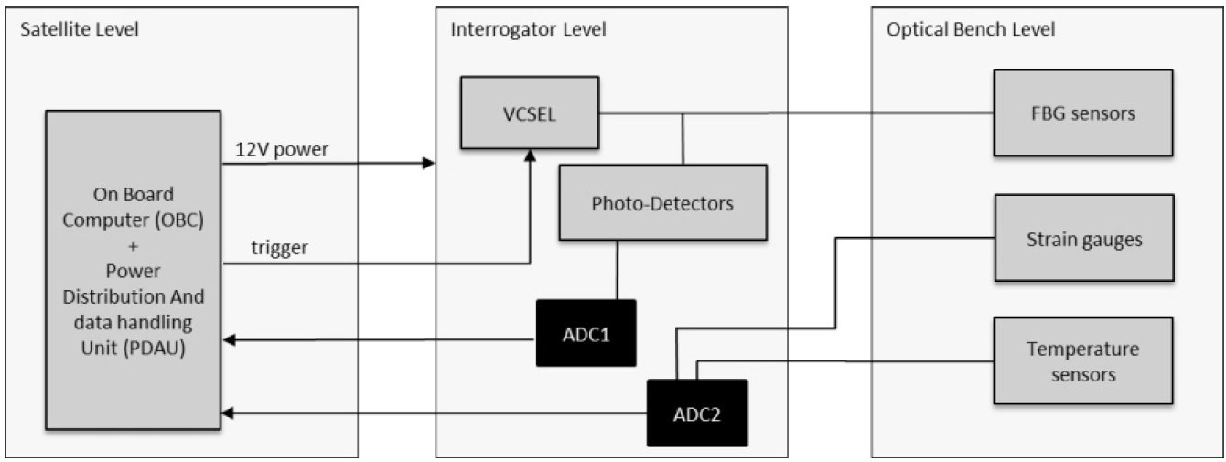
The performance of the smart structure of the PEASSS pathfinder will be assessed with four Fiber Bragg Grating (FBG) strain sensors and two FBG temperature sensors. FBG sensors consist of optical fibers that reflect particular wavelengths of light in a very narrow band (Bragg Wavelength) while transmitting all others. FBGs are sensitive to strain and the Bragg wavelength is also sensitive to temperature, allowing FBGs to be used as strain gauges and thermal sensors.
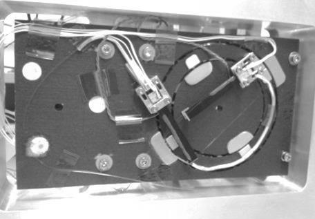
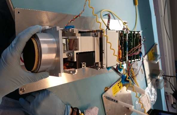
Within PEASSS, a simulated optical bench hosts two piezoelectric bimorph actuators to move a gimbal comprising a composite ring and composite disk. Deformation of the bimorphs will be measured by FBGs and a pair of Fine Sun Sensors (one fixed & one moving) provide an absolute reference measurement and electrical strain gauges provide measurements for comparison with the FBGs.

A Vertical-Cavity Surface Emitting Laser pumps infrared light into the optical fibers and sweeps through a wavelength range of 7 nanometers around the reference wavelength of 1535nm. When the laser matches the Bragg Wavelength of the FBGs, the light is reflected to multiple photodetectors which record the wavelength-dependent signal. A pair of analog-to-digital converters processes the output from the photodetectors as well as strain gauge & temperature reference sensors on the optical bench.
In addition to smart structures and their performance, PEASSS also sets out to qualify next generation power conditioning and data acquisition components for nano satellites incorporating “new energy scavenging methods and accommodating distributed sensor networks and novel data gathering techniques.”
DIDO-2
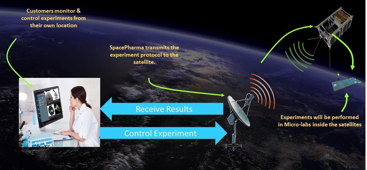
DIDO-2 is a micro-gravity research satellite designed by Swiss-Israeli company SpacePharma with the goal of developing a miniature laboratory that can be fully remote controlled and carry out research in the area of microbiology and biochemistry as well as microphysics. Complying with the 3U CubeSat form factor, the DIDO satellites facilitate the mGnify miniature laboratory systems housing a number of experiments.
The DIDO-1 satellite is manifested on a multi-payload launch of the Falcon 9 rocket out of Vandenberg Air Force Base, a mission that repeatedly slipped and is expected to launch in the first half of 2017. DIDO-2 was initially planned to fly on a Dnepr rocket, but shifted to a bulk satellite mission on India’s PSLV due to the doubtful future of the Dnepr that is likely to fall victim to the political dispute between Russia and the Ukraine.
According to SpacePharma, the DIDO satellites provide researchers access to the unique environment on microgravity using cutting-edge, miniaturized laboratories that can be controlled from anywhere. DIDO is based on a flight-proven satellite bus that takes up only half a CubeSat Unit, leaving 2.5U available for research equipment such as Lab-On-A-Chip technology, microscopes, spectrometers, SPuMP – a miniaturized microgravity pump, and other equipment. Control of individual experiments is possible via a secured web interface, enabling remote-control of the satellite from anywhere in the world.
DIDO-1 flies a SPmgLab unit, a space compatible end-to-end laboratory unit tasked with research in Bacterial growth, Antibiotics resistance, Self-assembly, Enzymatic reactions, Polymerization, Nanoparticle synthesis, Particle aggregation dynamics, Emulsion stability, Crystallization. The DIDO-2 mission is reportedly flying with a mGnify lab.
BGUSat
BGUSat is a 3U CubeSat developed by the Ben Gurion University, Israel in cooperation with Israeli Aerospace Industries, the country’s leading satellite manufacturer. The student-built satellite is based on a commercially available CubeSat Kit and carries multiple payloads including a camera, a space-based GPS receiver, optic communications systems and an experimental gyro & magnetometer unit.
The 4.3 Kilogram satellite hosts four deployable solar panels generating an average power of 6W fed to a pair of Lithium-Polymer batteries with a capacity of 3 Amp-hours. Attitude determination is accomplished with a three-axis magnetometer and a sun sensors while actuation of the satellite’s orientation in space is completed by magnetic torquers that provide sufficient pointing for power generation and imaging. Communications are handled in S-Band with uplink data rates of 1200bps for uplink and 9600bps for data downlink. The Main Control Unit of the satellite is facilitated on a central circuit board provided by Pumpkin, hosting an 8MHz CPU along with various in/output ports, watchdog timers, and data storage.
The primary payload of BGUSat is a medium-resolution CCD camera delivering 648 by 488 pixel imagery of Earth. Engineering payloads include a tri-axis gyroscope with digital range scaling built by Analog Devices, an experimental spaceborne GPS sensor, and a Honeywell Smart Digital Magnetometer to be demonstrated for future small satellite missions.
Al-Farabi-1
Al-Farabi-1 is a 2U CubeSat built by students at Al-Farabi Kazakh National University under the framework of an educational project. Initiated in 2013, the project went through one year of mission development and requirements definition before heading into subsystem and software development followed by the construction of an engineering model for testing to lead into the production of the final flight model. The initial development timeline of two and a half years significantly drifted to the right as is common in spaceflight project.
The main objective of the project is to give students practical experience in the development of a satellite mission, operation of the satellite is classed as a bonus objective. If functional in orbit, Al-Farabi would be used to fine-tune communications algorithms, satellite attitude determination and control software, and test the longevity of self-made components on the satellite.

Al-Farabi is outfitted with a commercially available spaceborne CMOS camera. The 166-gram NanoCam camera system was developed by GomSpace, Denmark for use on CubeSat missions. The camera is a full-color CMOS camera for Earth observation experiments, based on a modular system to enable rapid implementation while also allowing for customization according to specific mission requirements.
NanoCam C1U is an off-the-shelf design of the camera, comprised of a lens, lens table, focal plane assembly, image processor and software. The lens makes use of an industrial design from Schneider Optics, installed on the lens table which acts as the load-bearing structure of the camera. NanoCam has a 9.22-degree field of view.
The CMOS sensor is located at the top side of the assembly coupled to a printed circuit board underneath the lens table.

NanoCam employs a three Megapixel 10-bit CMOS detector comprised of 2048 by 1536 pixels. This enables the camera to cover a 165 by 125-Kilometer ground area with a spatial resolution of 80 meters. The detector operates at a maximum frame rate of 12 frames per second with 83.3 milliseconds required per capture.
The integrated processor of the NanoCam can support 210 MIPS (Million Instructions per Second), hosts 32MB of onboard RAM, 2GB of solid state memory and makes use of a JPEG compression algorithm. The communications interface between NanoCam and the satellite is a I2C (Inter-Integrated Circuit) using a serial protocol to achieve a data transmission rate of 400kbit/s and support bidirectional connectivity.
Al Farabi-1 employs an active attitude determination and control system with four sun sensors, a three-axis magnetometer and three-axis gyro acting as attitude sensors and three reaction wheels and three-axis magnetotorquers as actuation devices. The satellite is programmed to automatically dampen body rates after launch and put the satellite into a solar-pointed orientation to initiate nominal operations. Pointing for imagery acquisition is commanded based on time tables provided during regular command uplinks.
Power generation is completed by 16 solar cells installed on four side panels of the satellite feeding a 19 Watt-hour Li-Po battery unit. Spring loaded antennas reside on the top and bottom panels of the satellite, operating at 145 MHz for command downlink and 435MHz for data downlink, achieving a data rate of 4800bps.
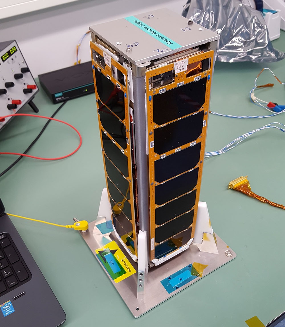
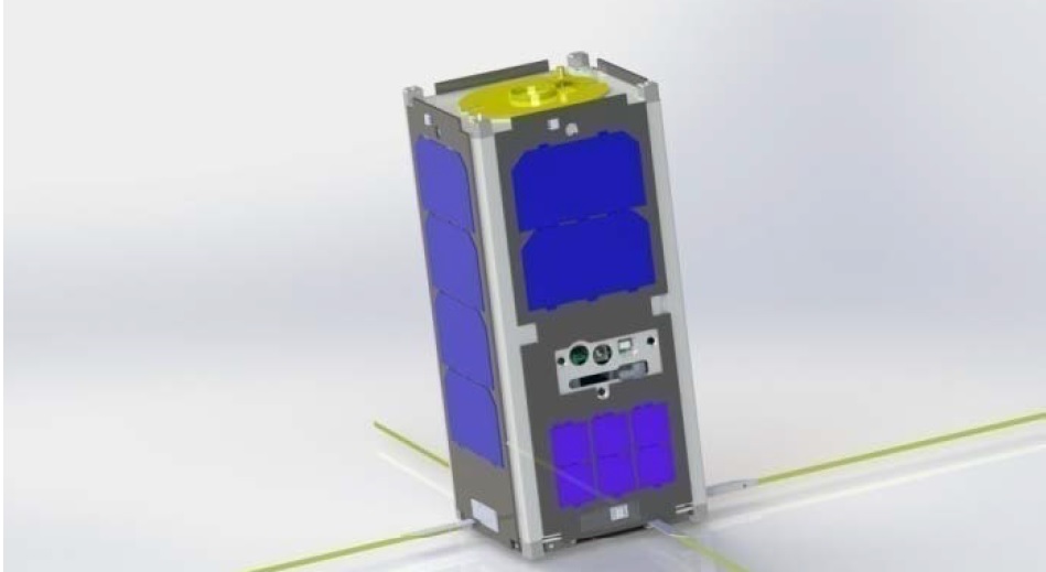
Nayif-1
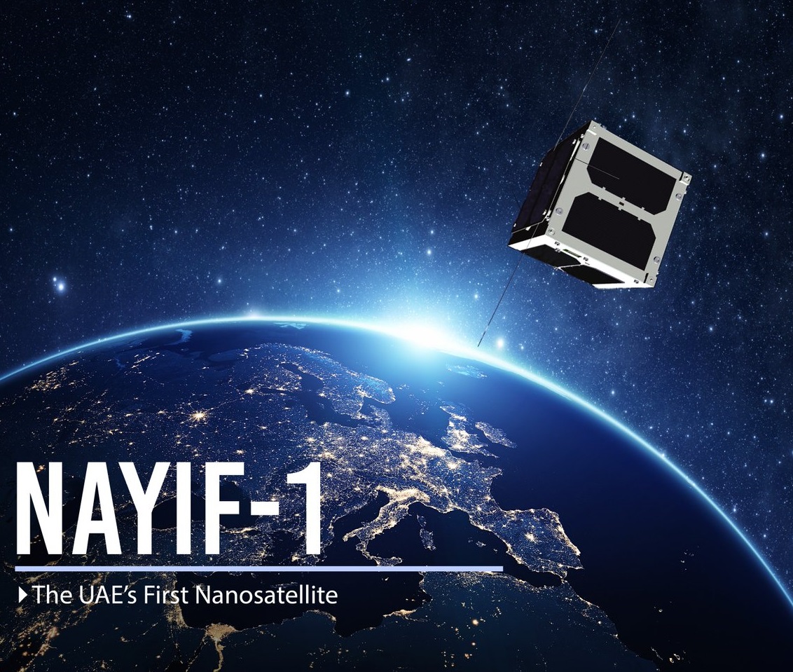
Nayif-1 (FunCube-5) is the first NanoSatellite of the United Arab Emirates, developed at the Mohammed bin Rashid Space Centre (MBRSC) and American University of Sharjah (AUS). The 1U CubeSat is outfitted with a FunCube amateur communications payload provided by the Radio Amateur Satellite Corporation.
The primary objective of the 1U CubeSat Project was to give Emirati students hands-on experience in the design, development, manufacture and operation of a satellite mission. Seven students from various engineering disciplines were assigned to the project to go through the entire mission design, test and operation process. Nayif-1 initially aimed for a 2015 launch atop a Falcon 9 rocket but had to shift to India’s PSLV rocket due to excessive delays in SpaceX’s manifest.
The primary payload of the 1.1-Kilogram satellite is FunCube-5, an amateur communications terminal for use by the radio community and for educational purposes. The payload hosts a new UHF to VHF linear transponder operating at 435.045 MHz for uplink, 145.960MHz for downlink and providing a beacon at 145.940 MHz.