
Meteor-M 2-1 Satellite Overview
Meteor-M 2-1 is the third in Russia’s fourth-generation of polar-orbiting weather satellites, building one of two segments deemed critical for an operational weather now- and forecasting capability, the other being high-altitude satellites in Geostationary Orbit. Geostationary Satellites are parked over the same location of Earth, allowing them to deliver imagery in near real time and at rapid revisit intervals to track weather systems and collect spectral data while the polar-orbiting constellation segment makes less frequent passes but delivers extensive atmospheric readings through multi-band imaging and sounding measurements.
The Meteor project dates back to 1961 when the Russian government initiated the development of a constellation of meteorological satellites carrying TV camera systems for monitoring of cloud cover, particularly for military purposes such as the operation of photo-reconnaissance spacecraft that carried a limited amount of film and relied on clear skies to acquire imagery of ground targets.

Development for the Meteor satellite series included the implementation of a gyro system for spacecraft stabilization, a revolutionary development as the space program was still in its early beginnings. In 1963, two testbed satellites were launched to demonstrate the three-axis stabilization system as well as new solar array technology and thermal protection for prolonged sun exposure. The first experimental Meteor satellite was launched in 1964 followed by nine more until 1969 while the 11th was lost in a launch failure.
The operational Meteor-1 generation was inaugurated in 1969 and saw 27 launches through 1977. The Meteor-1 satellites carried an optical instrument with a ground resolution of under three Kilometers, a TV infrared imager with a resolution of 15km and a radiation sensor.
Meteor-2 was inaugurated in 1975 and featured a number of improvements such as the addition of a five-channel scanning radiometer and the use of three visible/infrared frame scanners. A total of 21 Meteor-2 spacecraft were launched until 1993. Six Meteor-Priroda were launched between 1974 and 81 using the Meteor-2 bus, but featuring a payload comprised of four Multispectral Scanners with a ground resolution up to 28 meters, a Passive Microwave Radiometer, an infrared spectrometer and a radiation sensor.
The Meteor-3 satellite series saw six successful launches between 1985 and 1994, collecting data with a pair of TV imaging systems across a wide ground swath plus a multichannel spectrometer, a radiation sensor, an ozone-mapping instrument and two international payloads – the Scanner for Radiation Budget of the French Space Agency and the German Microwave Tracking System.
Meteor-3M No. 1 was launched in 2001 and initially planned to become the first in a series of advanced satellites carrying nine instruments including optical imagers, infrared and microwave sounders, space weather sensors and specialized instruments for aerosol and atmospheric constituent measurements. Plans existed to fit the second satellite with a high-resolution Earth observation instrument from the Resurs satellite series, but the Meteor-3M program was canceled in favor of the Meteor-M program that was in development at the time.
Delays with Meteor-M and the failure of Meteor-3M in 2006 caused Russia to drift into a gap of domestic weather data, requiring them to purchase data products from other agencies to continue high-quality weather forecasting.
The first Meteor-M satellite, designated Meteor-M 1, launched in September 2009 to demonstrate the satellite bus and the new instrument developments that use state-of-the-art components to collect high-quality data products according to international meteorological standard. Meteor-M 1 also closed a three-year gap in Russia’s capability of collecting weather data from polar orbit.
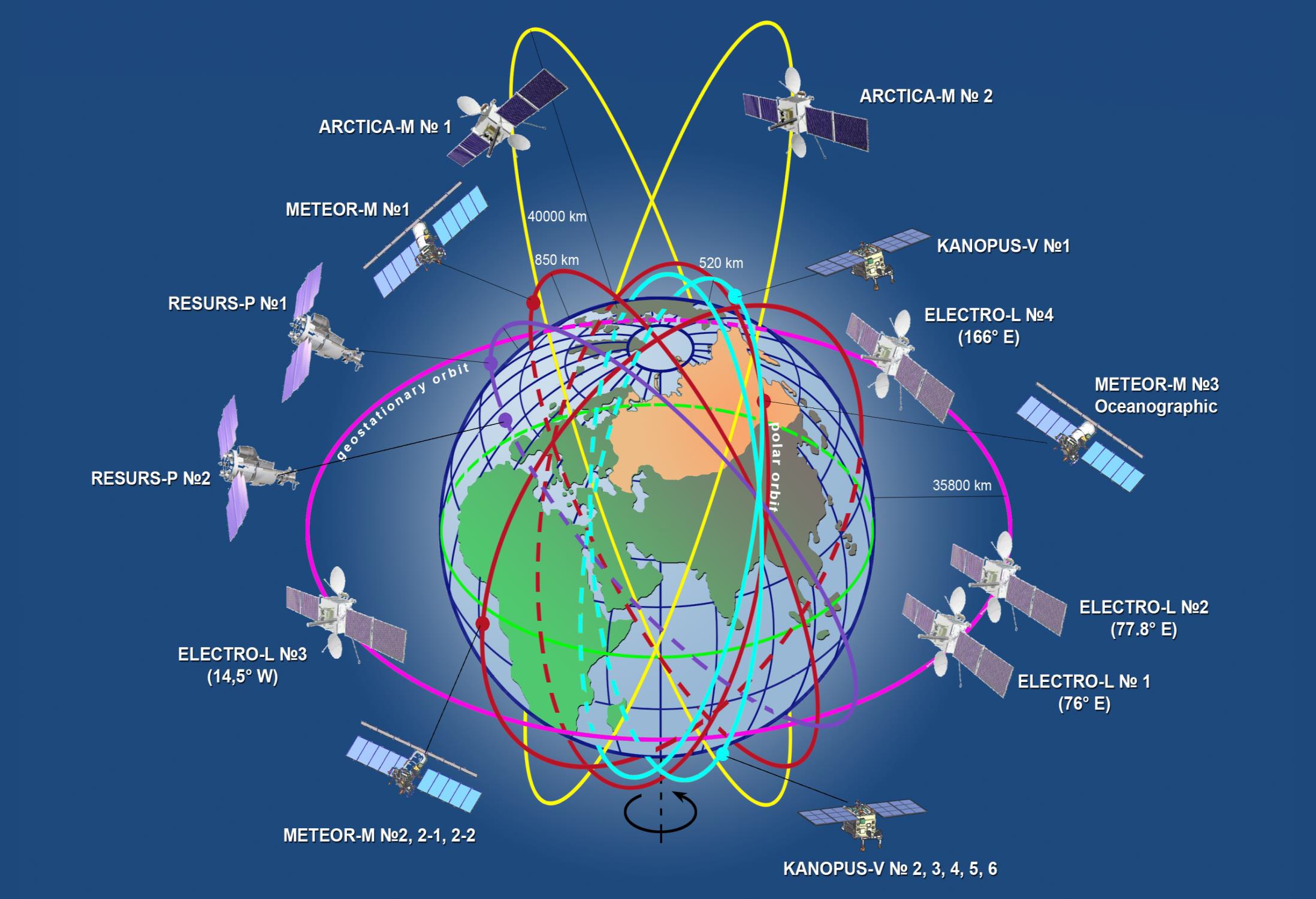
Meteor-M represents the next generation of meteorological satellites that were planned to restore Russia’s capability of gathering meteorological data. The plan for re-instituting Russia’s weather satellite system called for at least three satellites in sun-synchronous orbit and three spacecraft in Geostationary Orbit – the polar-orbiting satellites are flying under the Meteor designation while Geostationary data collection is accomplished with the Elektro-L satellites.
The Meteor-M 1 satellite successfully operated for five years & two months and was relieved by Meteor-M 2, representing an improved version of the M 1 satellite to inaugurate the first in the production-class of Meteor-M 2 that is expected to ensure availability of weather data into the 2020s.

Meteor-M 2 launched in July 2014 after over a year of delays due to technical difficulties with the satellite’s instrument payload, again taking Russia close to losing its polar-orbit data collection capability with only four months of overlap between successive missions.
Meteor-M 2-1 and 2-2 are planned to launch in 2017 and 2018 to establish an operational two-satellite system with one collecting data from a morning orbit while the other crosses the equator on the afternoon. According to documentation, Roscosmos and Roshydromet have ordered five similar Meteor-M 2 satellites to ensure operations can continue until at least the mid-2020s. Meteor-M 3, a specialized oceanographic satellite, is currently in development for launch in 2020 hosting a new-generation phased array radar to measure ocean states and wave height.
The Meteor program is operated by the Roscosmos State Corporation as Russia’s federal space agency, Planeta (Scientific Research Center of Space Hydrometeorology) and Roshydromet (Federal Service for Hydrometeorology and Environmental Monitoring). The primary objectives of the Meteor program are fourfold: a) weather analysis and forecasting on global and regional scales, b) global climate change monitoring, c) sea weather monitoring and forecasting, and d) space weather analysis and prediction.
The Meteor-M satellites are built by RSC VNIIEM, Moscow, each satellite weighing 2,700 to 2,900 Kilograms including 1,200 Kilograms for the multi-instrument payload suite. The Meteor-M satellites share a series of common instruments, but some instruments are specific to each spacecraft to optimize the data collected across the system.
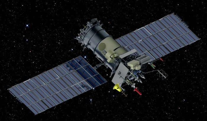
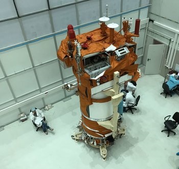
The defining characteristics of the Meteor-M 2-1 satellite is a large cylindrical satellite body with pressurized section, two deployable sun-tracking solar arrays, a large deployable synthetic aperture radar antenna and a rectangular payload deck that hosts the majority of the instruments and instrument apertures of the satellite being pointed to Earth for observations. The satellite bus shares commonality with the Resurs Earth observation spacecraft.
For precise Earth observation, Meteor-M requires precise attitude control. Therefore, star trackers are used for precise attitude determination and reaction wheels are used for attitude actuation.
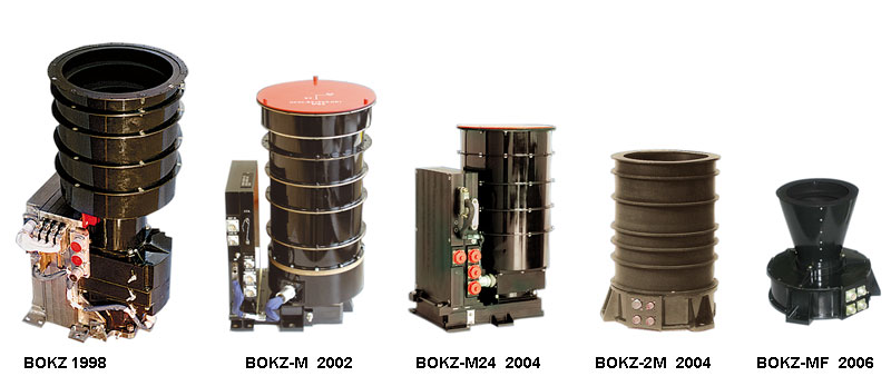
Meteor-M employs BOKZ-M star trackers build by IKI to identify and track star patterns to accurately calculate the vehicle’s three-axis attitude using an onboard algorithm. The star tracker weighs about four Kilograms, is 37 by 23 by 23 centimeters in size and operates at a data update frequency of 0.3Hz (one update every three seconds). The star trackers can support spacecraft slew rates of up to 0.2°/s. CCD detectors are used by the star trackers coupled to a power signal processor.
The system can tolerate artificial objects in the field of view and delivers a three-axis attitude solutions at an accuracy of 2/20 arcsec on all axes. The satellite also uses secondary attitude determination sensors as a backup and during sun-exclusions on the star tracker. Overall, Meteor-M achieves a pointing accuracy of 0.1° with an angular drift rate of 1/2000°/s.
A hypergolic propulsion system holding around 200kg of propellant is used for orbit adjustment maneuvers and orbit maintenance. Meteor-M 2-1 features two deployable solar arrays attached to the main cylinder of the satellite platform. Each array consists of five panels for a total solar array span of 14 meters and an array area of about 23 square meters. The arrays are rotated by the Solar Array Drive Mechanism that uses sun-sensor data to keep the arrays pointed at the sun while the satellite maintains an Earth pointing attitude. The solar arrays deliver 2,000 Watts of electrical power that is fed to onboard batteries for storage and distribution to the various subsystems of the spacecraft.

Meteor-M 2-1 uses a communications system compliant with standards of the World Meteorological Organization. The system includes a multi-frequency transmission system to allow downlink of instrument data using LRIT (Low Rate Information Transmission) and HRIT (High Rate Information Transmission). An X-Band Terminal is used for the transmission of high-rate data at a selectable transmission rate of 15, 31, 61 or 123 Mbit/s at a frequency range of 8.025 to 8.400 GHz. The system also includes an L-Band terminal that reaches a data rate of 665kbit/s at a frequency of 1.7Ghz. VHF data transmission at 137MHz is used for the real time downlink of Low-Resolution Multispectral Scanner data in LRPT.
The Meteor-M spacecraft also support the relay of data from worldwide DCPs (Data Collection Platforms). DCPs can be deployed virtually at any location on the globe to provide in-situ measurements of meteorological data that is then uplinked to satellites and transmitted to ground stations for collection, processing and distribution. The DCPs operate in the UHF band at 401/402 MHz and transmit data packets of 250bits at data rates of 400 to 1200bit/s. Over the course of one orbit, the satellite collects about 300KB of DCP data that is downlinked via the 1.7 GHz L-band terminal.
Instrument Overview
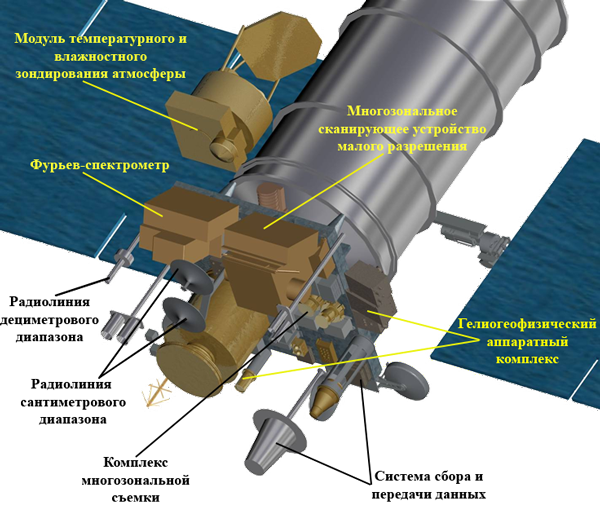
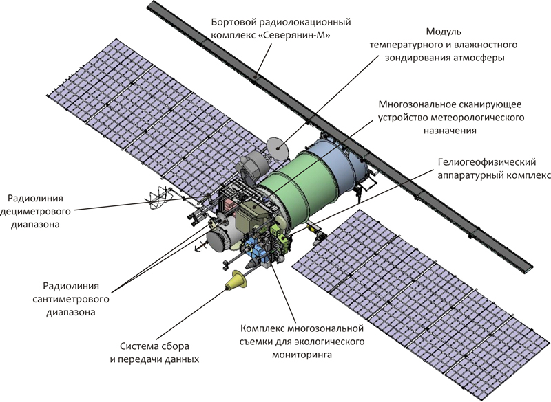
The Meteor-M 2-1 satellite carries a suite of six instruments: MSU-MR (Low Resolution Multispectral Scanner for Cloud Cover Mapping), KMSS (Multispectral Imaging System), MTVZA (Microwave Imaging & Sounding Radiometer), IRFS-2 (Infrared Sounding Instrument for temperature and humidity profiles & surface winds), the SSPD Data Collection and Transmission System, and the S&RSAT Search and Rescue Satellite-Aided Tracking System.
The Meteor-M 2-1 and 2-2 do not fly with Severjanin-M Onboard Radar Complex and GGAK spectrometers for geoactive measurements and radiation monitoring that were part of the Meteor-M 2 payload suite. Starting with the 2-3 spacecraft, the Meteor-M 2 series will fly with advanced versions of these instruments known as GGAK-M/MSGI-MKA, GGAK-M/KGI-4C and MeteorSAR as an upgraded radar payload.
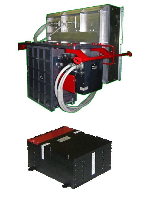
MSU-MR is a 70-Kilogram Multispectral Scanning Payload that covers six spectral bands for global and regional cloud cover monitoring and sea and land surface temperature measurement. The instrument covers one visible spectral band, one crossover band and four infrared bands. The visible channel has a wavelength range of 0.5-0.7 µm, the Visible-Near-Infrared channel 0.7-1.1 µm, the short-wave IR channel 1.6-1.8 µm, the mid-wave IR channel 3.5-4.1 µm and the two thermal infrared channels cover 10.5-11.5 and 11.5-12.5 µm.

The instrument’s scanning mechanism sweeps out a +/-54-degree cross-track swath corresponding to 2,800 Kilometers on the ground, allowing MSU-MR to cover the entire Earth twice per day. Products delivered by MSU-MR include diurnal cloud maps, sea and land surface temperature, brine color, land feature, clouds properties, aerosol distribution, and atmospheric water vapor content.
The rotating Scan Mirror Assembly feeds light into a telescope system that directs the image to beam-splitting optics which route the respective wavelength bands to their focal plane assemblies using cooled detector assemblies for the infrared wavelengths and focal planes at ambient temperature for the VIS/NIR channels. MSU-MR uses 1540 pixels in line in the cross-track direction and six lines in the along-track direction, yielding and instantaneous field of view of 1.0 Kilometers, an angular resolution in all channels of under 1.4mrad. The temperature measurement error in the IR channels is less than 0.5 Kelvin at an operational radiation temperature range of 212 – 313 K. The instrument is operated continuously, generating a steady stream of data at a rate of 660kbit/s.
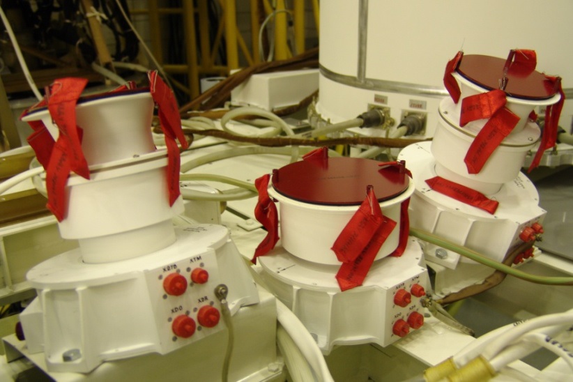
The KMSS Multispectral Imager, built by IKI (Space Research Institute), consists of three pushbroom imagers covering the visible and infrared spectral regions for surface monitoring applications. Two of the three cameras have a 100-millimeter focal length (MSU-100) and one has a focal length of 50 millimeters (MSU-50). The MSU-100 is 21 by 20 by 20 centimeters in size with a mass of 2.9 Kilograms while the MSU-50 is smaller, being 21 by 20 by 14 centimeters in size with a weight of 2.3kg.
The three cameras have identical CCD detectors with 8000 pixels in the cross-track directions and three CCD lines covered with different bandpass filters to set the instrument’s spectral coverage. The MSU-100 covers three spectral bands: 535-575, 630-680 and 760-900 nanometers while the MSU-50 covers the following VIS bands: 370-450, 450-510, 580-690nm. MSU-100 has a field of view of 31° while the MSU-50 has a wider FOV of 62°. The two MSU-100 Cameras are installed at a 14° angle in cross track to acquire images of adjacent regions to create a cumulative swath width of 960 Kilometers while the MSU-50 alone covers a 940km swath with corresponding ground resolutions of 60 and 120 meters.
Earth Observation Data Products provided by KMSS are combined images of all three cameras generated during ground processing. The 8.1-Kilogram instrument delivers a source data rate of 60 Mbit/s, 9.8 Mbit/s per band.
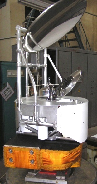
The MTVZA-GY instrument is a passive 29-channel, conical-scanning Microwave Radiometer gathering radiometric brightness data for 21 different frequencies across a wide ground swath to deliver atmospheric profiles for temperature and humidity, oceanographic and selected land parameters on a global scale including cloud structure, sea surface winds, rain rates, cloud water, precipitation, soil moisture, etc.
MSU, KMSS and MTVZA are the three most critical instruments aboard the Meteor satellite, delivering information on cloud motion and atmospheric profiles needed for operational weather forecasting.
The 90-Kilogram MTVZA instrument consists of a large rotating main reflector and an Instrument Support Structure facilitating the RF electronics and sensors as well as the spin mechanism and support systems. The operating frequencies of the instrument cover the transparent atmospheric range, the oxygen absorption lines and the water vapor absorption range.
As a conical-scanning radiometer, MTVZA uses a spinning offset parabolic reflector 65 centimeters in diameter to sweep out a cone-shaped swath on the ground, reflecting natural microwave emissions to separate feed horns connected to receiver circuits. The antenna is angled 53.3 degrees to set up a 65-degree incidence and rotates at a speed of 24.9 revolutions per minute, designed to assemble an uninterrupted swath as the satellite moves along in its orbit, covering a ground swath of 1,500 Kilometers.
MTVZA scans a clear viewing sector of 106 degrees centered on the anti-velocity vector of the spacecraft – scanning behind the spacecraft and biting off 15.8 Kilometers in the along-track direction with each successive scan. The rest of each 360-degree revolution is used for calibration operations. For morning ascending node spacecraft, the instrument observes an area aft of spacecraft nadir while morning descending node spacecraft are scanning an area forward of nadir.

The instrument covers a total of 29 channels with frequencies of 10.6 GHz to 183.31 GHz to retrieve temperature and moisture profiles from ground level up to an altitude of 80 Kilometers. All channels are switched to four feed-horn antennas and a total-power radiometer design is employed to create a better sensitivity, utilizing a combination of dual-polarization (10-48 GHz, 91.65 GHz) and single (horizontal) polarization channels. The seven 10 to 48 GHz channels use direct amplification radiometer technology while the 52-57, 91 and 183 GHz channels use superheterodyne receiver chains with balanced mixers.
The footprint sizes vary with the frequency of the individual channels – the seven 10-48 GHz channels have 32 Kilometer pixels, channels between 52.8 and 57.3 GHz have 48km pixels, the surface channel at 91.65GHz has 16km pixels and the three 183GHz channels have 32 x 32 km pixels – the vertical resolution of atmospheric profiles varies between 1.5 and 7 Kilometers. The lower frequencies have larger beamwidths that have sufficient overlap in the along-scan direction to achieve a continuous and complete coverage; the high-frequency channels no longer have overlap from one scan to the next causing gaps in coverage; however, the minimum coverage requirement is maintained with the IFOVs of these channels.
Instrument Calibration is accomplished by a cold sky target and a hot load that are being scanned as part of the calibration cycle of each instrument rotation, occulting the feed horns once per rotation.
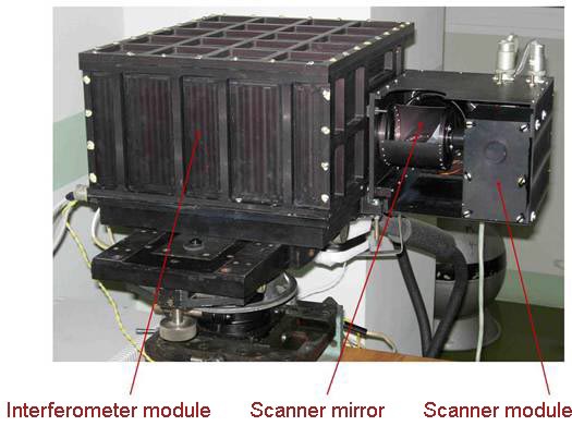
The IRFS-2 – Infrared Fourier Spectrometer 2 instrument is an infrared sounder built by the Keldysh Center to refine the atmospheric profiles collected by the microwave radiometer and deliver additional data on atmospheric constituents and aerosols. The instrument consists of an optical unit, a data processing / power supply unit and a radiative cooler that keeps the focal plane at an appropriate temperature to reduce the dark current of the detectors. The optical system is comprised of an interferometric module with a double pendulum interferometer and a radiometer, a pointing module and a calibration module.
Hyperspectral infrared sounding has become a powerful tool for more accurate, detailed atmospheric observation which, when combined with microwave soundings, yields much improved short-term weather nowcasting and longer-term forecasting in the three to seven-day range.
The interferometer uses a standard plane-mirror configuration in which incoming light is split with a beam splitter device onto two optical paths created by flat mirror systems with one path at constant length and the other varied by moving the mirror to create an interference pattern on the detector that is dependent on the path difference which is precisely known through accurate measurement of the moving mirror position.
An interferogram is created by taking measurements of the signal at many discrete positions of the moving mirror. Fourier transformation then converts the interferogram into a high-resolution spectrum (with resolution depending on the number of discrete measurements).
The major advantage of Fourier Transform Spectrometry over dispersive spectrometers (grating or prism spectrometers) is a higher spectral resolution and much improved signal to noise ratio since the interferometer’s detector effectively monitors all wavelengths simultaneously throughout the measurement as opposed to grating spectrometers where the measured wavelength varies across the detector.
IRFS-2 covers a total of 2,670 spectral channels over a spectral range of 5 to 15 µm at a spectral resolution of 0.5cm-1. The instrument’s scanning assembly operates in a step-and-scan fashion with two operational modes – continuous cross-track stepping with 30 steps to cover a swath of 1,000 Kilometers or opting for a wider swath of 2,500 Kilometers with gaps between successive steps. The spatial resolution achieved by the 50-Kilogram instrument is 35 Kilometers at the sub-satellite point and 70 Kilometers at the swath edge. The radiometer operates at a temperature accuracy of 0.5K.
The instrument covers the carbon dioxide absorption band to obtain temperature profiles, two atmospheric windows for cloud properties and surface parameters, the ozone absorption band for ozone sounding and the absorption bands of water, nitrous oxide and methane for moisture profiles and column amount measurement of these substances.

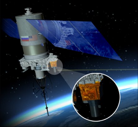
The SARSAT (Search and Rescue Satellite Aided Tracking) System enables the relay of distress signals from mariners, aviators, and other recreational users in distress at any position within the satellite’s footprint. The task of the spaceborne terminal is to relay distress calls to the SARSAT Mission Control Center which then sends them to the closest Rescue Coordination Center to begin the search and rescue effort in the area. Emergency messages can be transmitted at 406, 121.5 and 243 MHz and Doppler Information is used for location determination. The 51.5-Kilogram S&RSAT terminal on Meteor-M 2 provides twice-daily coverage of the entire globe.
The Meteor-M satellites use three main downlink stations spread from west to east across Russia: Moscow, Novosibirsk and Khabarovsk. 68 local centers are also used for data downlink and processing operations. Meteor-M data is distributed to the Russian government (e.g. Department of Defense, Emergency Control Ministry) and other institutions for weather forecasting, environmental monitoring and scientific purposes.
