
GOES-R, S, T, U Instruments
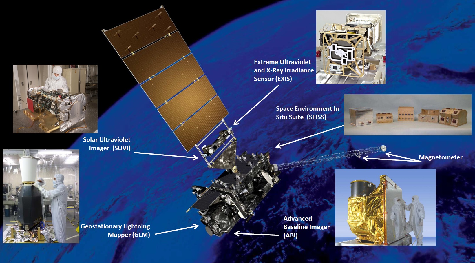
The GOES-R-class weather satellites host a suite of six instruments in three categories: Earth-Pointed Instruments (Advanced Baseline Imager ABI & Geostationary Lightning Mapper GLM); Sun-Pointed (Solar Ultraviolet Imager SUVI & Extreme UV and X-Ray Irradiance Sensor EXIS); and In-Situ Space Environment (Space Environmental In-Situ Suite SEISS & Magnetometer).
In a major change to the previous generations of GOES satellites, GOES-R and its successors omit a sounder instrument and instead extract equivalent sounding products from Advanced Baseline Imager data through ground processing. In place of a sounder, GOES now flies the Geostationary Lightning Mapper that greatly improves storm hazard identification in day and night for longer warning lead-time. The solar and space environment instruments also expand capabilities of previous GOES satellites.
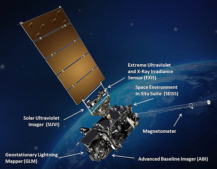
The two Earth-Pointed Instruments reside on an Earth-Pointed Platform that is passively isolated from the spacecraft body to dampen vibrations and ensure the instruments and attitude sensors are maintained in good alignment to ensure proper Earth-pointing at the highest possible accuracy & stability. A Sun-Pointing Platform attached to the solar array yoke hosts the two Solar instruments and provides adequate tracking of the seasonal and daily movement of the sun relative to the spacecraft.
The Advanced Baseline Imager (ABI) is a 16-channel multi-spectral scanning instrument capable of generating a global image of Earth every five minutes at a maximum resolution of half a Kilometer for cloud & weather pattern monitoring and the extraction of various atmospheric parameters. With an image acquisition time of five minutes and a spatial resolution between 0.5 and 2 Kilometers, ABI is the most capable meteorological imager operated from Geostationary Orbit (as of 2016).
GLM, the Geostationary Lightning Mapper, is a staring instrument covering the entire American continent to monitor lightning activity and hail on a 24/7 basis to improve forecast models and predict the transient evolution of severe storm events including tornadoes, hail storms and flash floods.
The Solar Ultraviolet Imager covers Ultraviolet and Soft X-Ray wavelengths to track solar activity at high temporal resolution to identify flares and other phenomena and deliver predictions for geomagnetic storms and potential satellite outages. The EXIS Extreme UV and X-Ray Irradiance Sensor delivers full disk imagery of the sun with a pair of instruments to keep track of solar variability and from that predict effects on ionospheric changes relevant for satellite operation (comms, navigation, drag).
The Space Environmental In-Situ Suite contains five instruments to measure charged and neutral particles and the electromagnetic environment in near-Earth space, differentiating between solar and galactic influences. MAG delivers measurements of the space environment magnetic field responsible for controlling charged particle dynamics in the outer atmosphere.
Advanced Baseline Imager
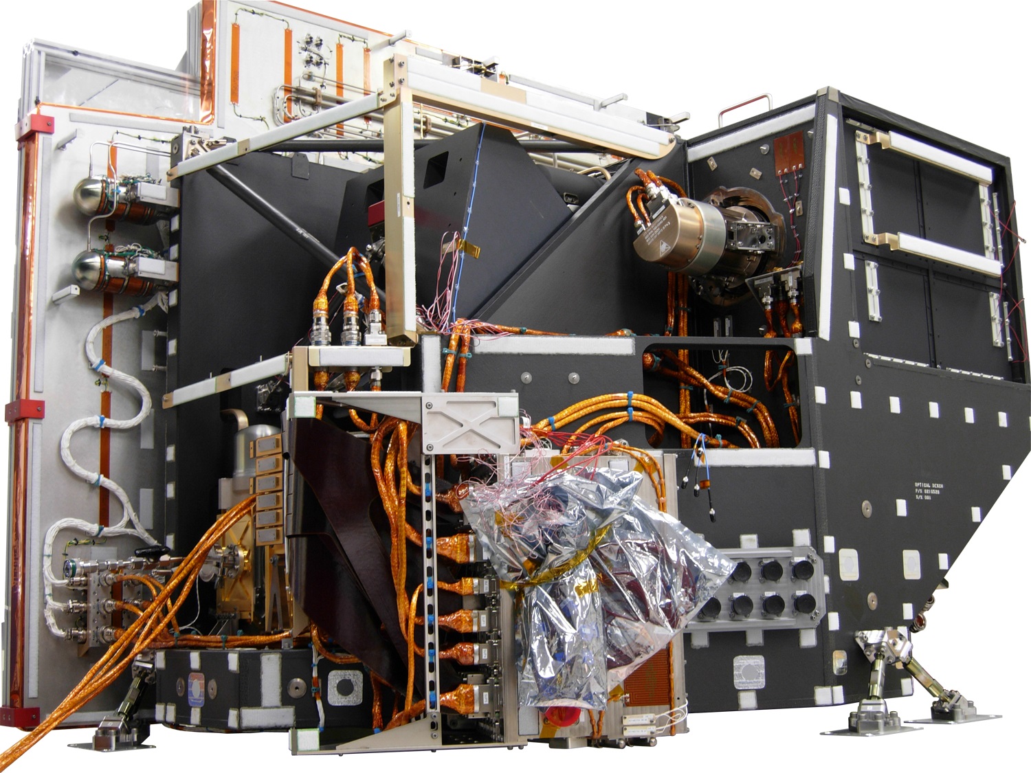
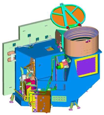
The Advanced Baseline Imager (ABI) is a third-generation multispectral imager with a two-axis scanning geometry, vastly expanding previous capabilities by adding spectral channels, improving spectral and spatial resolution of imagery, and employing a much faster data acquisition scheme. Weighing in at 125 Kilograms, ABI can be considered the primary instrument of the mission as it delivers relevant data for ground and atmospheric monitoring.
ABI opens a new era in remote sensing from Geostationary Orbit, delivering high-resolution imagery and radiometric information of the Earth’s surface, atmosphere and cloud cover that also allows the instrument to double as an atmospheric sounder. Prime requirements for ABI – in addition to an overall improvement in data quality & quantity – include additional scan flexibility, reduced data loss due to the sun and simultaneous data collection.
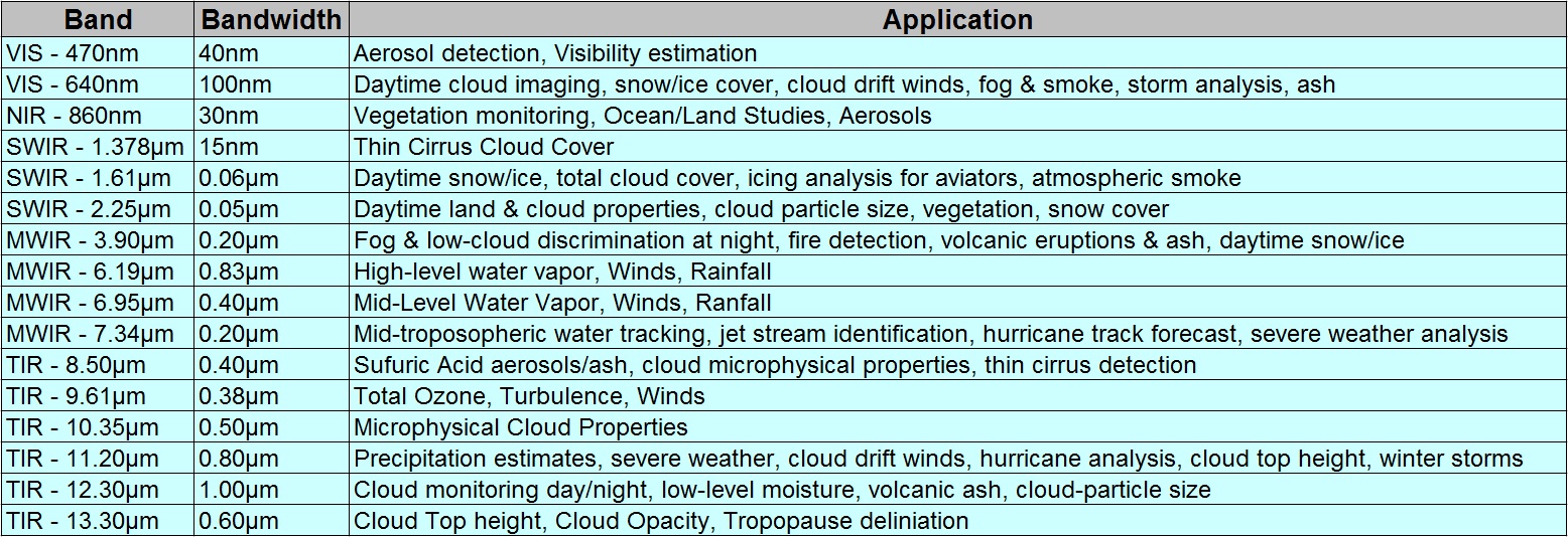
ABI employs a scanning mechanism that sweeps out an East-West image swath and steps in the North-South direction after each successive sweep, capable of assembling a global image every five minutes. It covers 16 spectral channels from the visible spectrum into the infrared wavelengths, marking a major increase in channels compared to heritage instruments.


ABI delivers 16 bands of multispectral data with two bands in the visible wavelengths and 14 bands spanning the short-wave, mid-wave and thermal infrared spectrum. The resolution is band dependent and ranges from 0.5km for the visible and 1.0km for short-wave IR to 2.0km for mid-wave and thermal IR. Three imaging sectors are offered by the instrument known as Full Disk, CONUS (Contiguous United States) and Mesoscale.
Full Disk imagery represents a full frame of the entire visible disk of Earth from the satellite’s GEO position, CONUS covers and area of 5000 by 3000 Kilometers and the Mesoscale sector can be freely chosen within the satellite’s Field of Regard for a 1000 x 1000-Kilometer area for monitoring of areas of interests, e.g. hurricanes in the oceans.
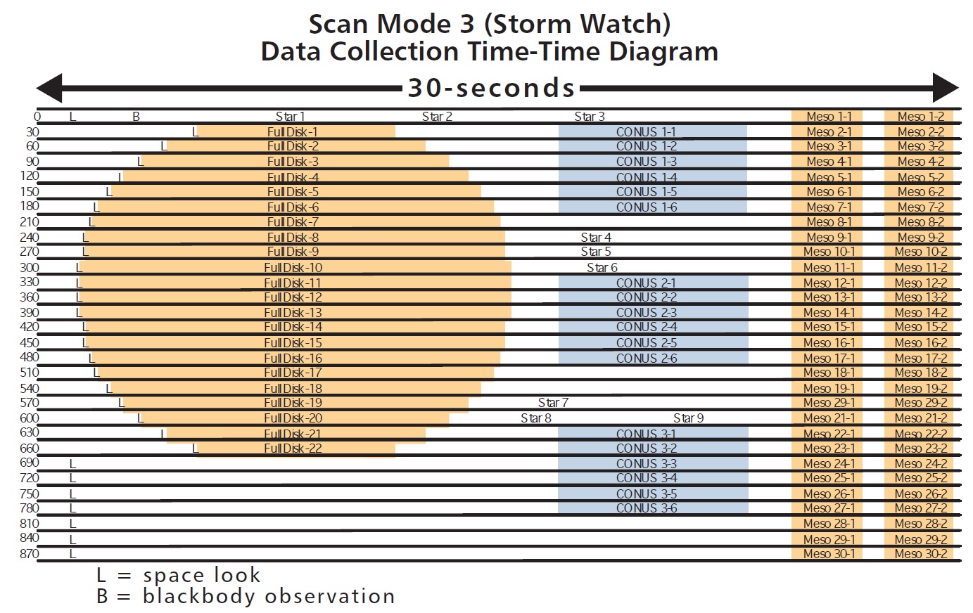
Two imaging modes are being used during operational GOES services – Mode 3 delivers one Full Disk, 3 CONUS and 30 Mesoscale images every 15 minutes while Mode 4 generates Full Disk images every five minutes plus 30 Mesoscale images every 15 minutes.
The acquisition of a Full Disk Image, 17.76° in diameter, requires ABI to make 22 North-South Steps with a pixel size of the full image of 22,141 at the highest resolution. CONUS images are 8.02 by 4.81 degrees in size and correspond to 10,000-pixels at the highest resolution; the 1.6 x 1.6° meso images have 2000 pixels in the VIS channels.
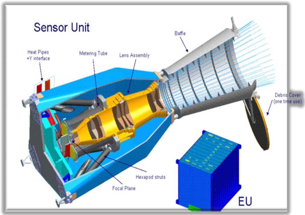
ABI facilitates three separate detector planes fed by a series of beam splitters and dichroic elements. The VIS detectors operate a ambient temperatures while the infrared detectors are actively cooled to reduce dark current and enhance image quality. The IR focal plane is cooled two a two-stage pulse tube cryocooler developed by Northrop Grumman, delivering a large cooling power at 53 and 183 Kelvin for the thermal and mid-IR detectors. The detector design has been chosen for its robustness to support the long mission duration for GOES. The cryocooler has a two cold head design with one head integral to the compressor assembly and one coaxial cold head.
Geostationary Lightning Mapper

The Geostationary Lightning Mapper, GLM for short, is hosted on the GOES-R class satellites instead of a sounding instrument because the Advanced Baseline Imager can fulfill the sounder function. GLM is a staring instrument sensitive in the near infrared band to capture the signature of lightning to measure the total lightning activity over the Americas in day and night conditions. In addition to lightning, GLM can also capture ice-phase precipitation.
GLM is a valuable addition to GEO weather observations – its data will be used to diagnose and forecast the evolution of severe storm events including tornado outbreaks, microbursts, hail storms and flash floods. Also, data from GLM will improve mesoscale forecast models and retrievals of convective properties. GLM is very rapid in acquiring lightning data, allowing for near-real time assessments of lightning activity while data records can provide insights into interannual variability of storms and lightning climatology.
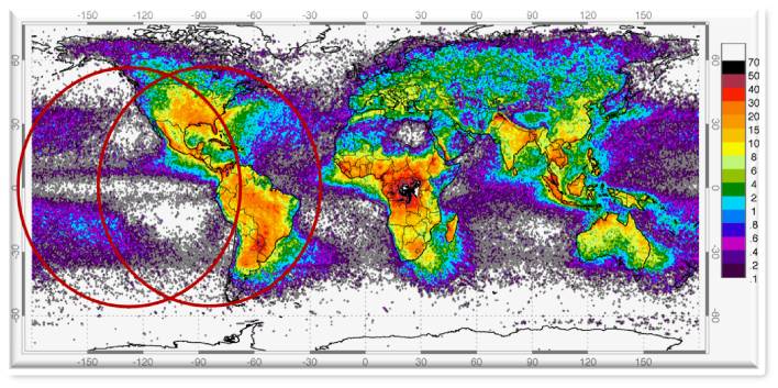
The prospect of obtaining near real-time lighting maps can be of great use in many areas such as aviation to navigate aircraft around convective weather and reduce fuel consumption as the result of re-routes. Application of lightning data for tornado activity forecasting will yield a greater warning time and reliability – creating a reduction of false tornado warnings.
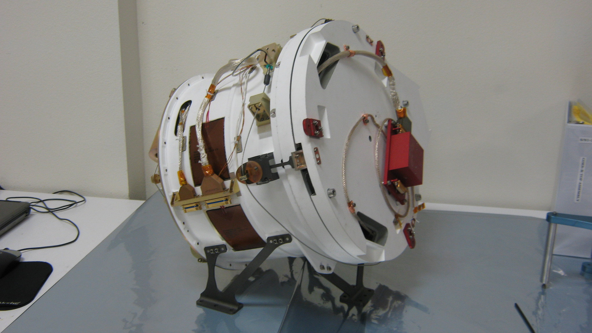
GLM is a staring imager optimized to detect the infrared signature of lightning. The 125-Kilogram instrument comprises an optical telescope, focal plane assembly, real-time event processing electronics, formatting electronics, power supplies and an interface electronics unit.
GLM’s telescope has a 12-centimeter aperture diameter with a f/1.2 lens that has a 134-millimeter focal length, creating an instrument field of view of +/-8 degrees.
GLM employs a narrowband filter system that selects the infrared band at a center wavelength of 777.4 nanometers and a bandpass of one nanometer – tuned to the oxygen triplet line very prominent in the lightning spectrum. The filters are comprised of three individual stages – a 30nm Solar Rejection Filter, a 3nm Solar Blocking Filter and finally the 1nm Narrowband Filter.
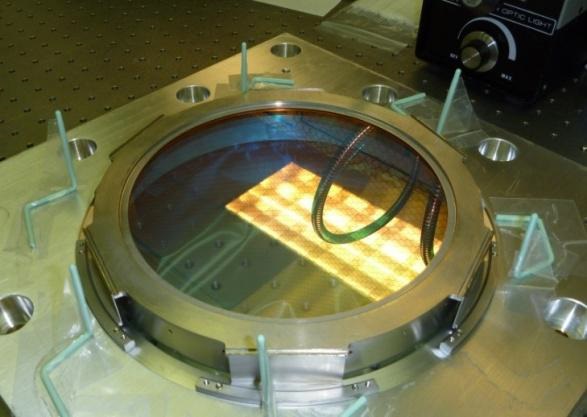
The telescope feeds a staring CCD detector array of 1372 by 1300 pixels with a variable pixel size. It achieves a variable spatial resolution of eight Kilometers chosen to match the typical storm cell size. GLM operates at a frame rate of 500 images per second, but does not transmit images and instead processes them in real time to work as a lightning event detector.
Raw frames are processed by the a real time processing system that is capable of identifying lightning signals whenever a selected signal difference threshold between frames is detected. The system can correctly identify more than 90% of lightning events with false alarms kept below 5% of total measured events. In terms of measurement accuracy, GLM can identify events at pixel scale, 8 to 14 Kilometers.

The Real Time Event Processor compares the value of each detector pixel to a stored background that represents an average of the recent history of that pixel. If the read-out from a pixel exceeds a selectable threshold, an event is triggered. The background is a moving average with an adjustable time constant that determines over how many recent images the average is built. This technique requires the internal instrument data system to transmit and process data at a rate of 5Gbit/s – a task split between multiple Real Time Event Processors.
When an event is triggered, the processing system creates a 64-bit data structure that includes the time, position of the pixel, its intensity with respect to the background, and the value of the backround itself. This processing technique reduces the instrument data output from a raw data rate of 12.5Gbit/s to less than 6Mbit/s of event data.
A challenge for GLM is identifying lightning during the day. This is achieved by spatial filtering – selecting the pixel resolution to match the typical cloud area illuminated by lightning to constrain events to single pixels, spectral filtering – selecting the wavelength where lightning emissions are the strongest, temporal filtering – setting the read-out rate to minimize pulse splitting and avoid lowering the signal to noise ratio, and finally setting the event processor to proper background and event thresholds. Individually averaging the background for each pixel is important because there can be quite strong contrasts between different cloud heights under low-angle solar illumination, allowing thresholds to be set individually for each pixel.
The event records transmitted by the spacecraft are put through a series of ground processing steps to remove non-lightning events caused by radiation hits and sun glints. This is done by virtue of coherency as lightning events are coherent events and noise-triggered events are more or less random. Lightning flashes can be several seconds long and will appear in the same or adjacent pixels while noise events will not be coherent in the temporal and local regimes.
The coherence filter of the ground processing chain calculates the probability of an event being an actual lightning event based on its intensity, electronics noise and background noise. When another event occurs in proximity, the filter calculates the probability of both of those events being noise taking into account their intensity, noise measurements and time between events.
Solar Ultraviolet Telescope
SUVI, the Solar Ultraviolet Telescope is one of two sun-pointed instruments on the GOES-R-class of satellites, delivering continuous full-disk coverage of the solar transition region and corona in six extreme ultraviolet wavelength bands. Data from the instrument is used for monitoring of the sun’s activity and space weather impacts on Earth.
Diagnostics of the thermodynamic state of the solar atmosphere has become an important aspect of forecasting, allowing for predictions of solar phenomena capable of impacting space weather.
Space weather forecasting has become important for the protection of human-engineered assets such as satellites, aircraft, radio communications system and power grids on the ground.
As a new generation EUV (Extreme Ultraviolet) imager, SUVI also offers a valuable scientific opportunity, delivering a wide-field of view of the corona over an extended period of time to provide insight into highly dynamic phenomena as well as variations on the longest time scales.
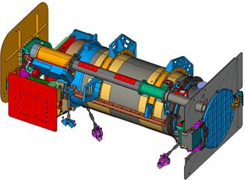
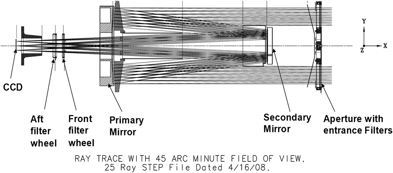
SUVI is comprised of a Cassegrain telescope using a six-segmented multilayer mirror that feeds a high-resolution detector assembly. Generalized Cassegrain-type telescopes make use of two mirrors placed on the optical axis of the telescope – a concave M1 primary mirror and an on-axis convex M2 mirror that focuses the light onto the Focal Plane Assembly. The distinguishing feature of SUVI is a six-segmented mirror with different reflective characteristics to select the six wavelength bands that are to be imaged.
The SUVI optics assembly comprises multilayer mirrors, thin-film metal filters and the back-illuminated CCD detector placed in the focus of the telescope. SUVI’s primary mirror is 20 centimeters in diameter while the secondary mirror is 9.2cm in diameter, creating a focal length of 173 centimeters. All optical elements are manufactured from Zerodur, a material typically selected for telescopes operated in space due to its robustness and extremely high thermal stability.
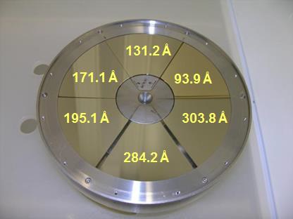
Each optical element of the telescope has six distinct multilayer coatings in six pie segments that reflect a fine-tuned wavelength – 93.9, 131.2, 171.1, 195.1, 284.2 and 303.8 Angstroms corresponding to different temperature regions of the solar atmosphere.
The CCD detector employed by SUVI is 1280 by 1280 pixels in size, featuring standard 21 x 21-micrometer pixels. The instrument has a 53.3 by 53.3-degree field of view which makes imaging of the full solar disk possible. Typical exposure times vary from one second to 10 milliseconds and images are taken every ten seconds, delivering imagery of each band once per minute and creating a two-minute refresh rate for the full dynamic range of the instrument.
Extreme Ultraviolet and X-Ray Irradiance Sensors
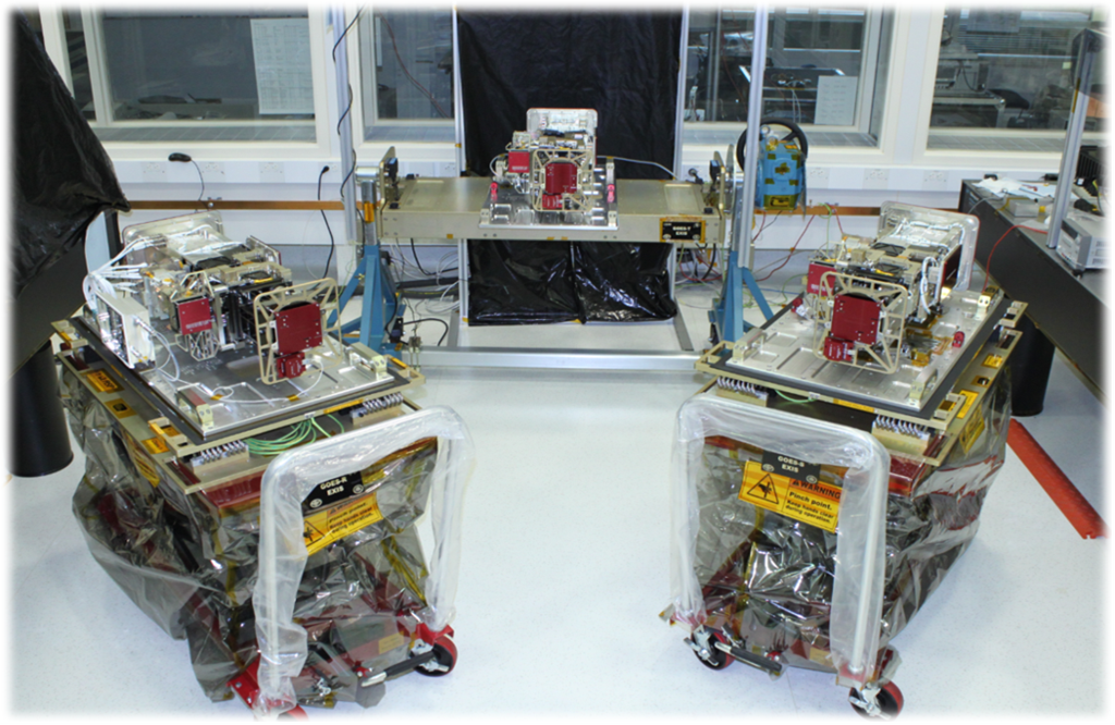

The Extreme Ultraviolet and X-Ray Irradiance Sensors (EXIS) are the second component of the GOES sun-pointed payload. EXIS contains two full-disk instruments: EUVS – the Extreme UV Sensor and XRS – the X-Ray Sensor. EUVS delivers EUV spectra for modeling of the solar influence on Earth’s thermosphere and ionosphere while XRS data is primarily used for flare detection. Both components have been designed and built at the University of Colorado.
EXIS measures 76 x 30 x 37 centimeters in size and weighs 30 Kilograms, comprising four principal components – EUVS, XRS, the instrument electronics box and sun positioning sensors.
The EUVS sensor comprises three reflection grating spectrographs covering bands for the emissions from the chromosphere, transition region and corona. Two of the spectrographs are normal incidence spectrogaphs while the narrow-band spectrograph uses grazing incidence optics for the transmission of radiation.
The typical design for the spectrographs calls for radiation, in this case extreme UV radiation, to enter through a lit, pass onto a mirror that focuses the light into the dispersive element that separates the different wavelengths of the light and reflects it onto another mirror that focuses the dispersed light onto the focal plane hosting silicon photodiode detectors.
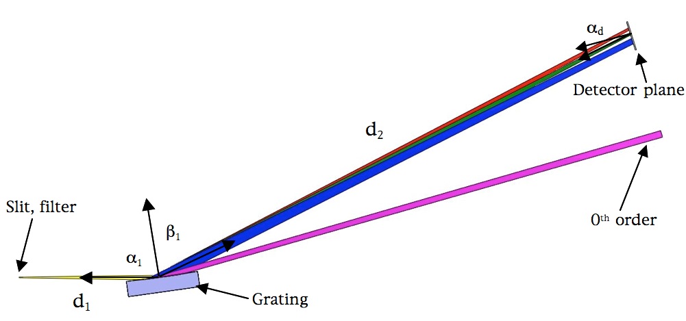
Grazing incidence optics are needed for extremely low wavelength channels because EUV and X-rays can only be reflected at extreme angles. Each spectrograph has a 1.5° square field of view.
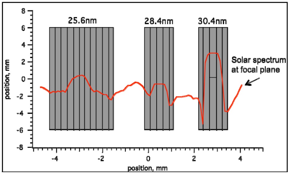
The EUVS Grazing Incidence Spectrograph covers a wavelength band of 25 to 31 nanometers and achieves a spectral resolution of 0.7 nanometers. Within this band falls a prominent coronal iron emission band at 28.4nm and a pair of He transition lines.
EUVS-A employs an off-Roland cycle grazing incidence spectrograph with a 0.4mm wide and 4.0mm high entrance slit. A filter wheel holds multiple identical filters of 200-nanometer aluminum sandwiched in 10nm layers of carbon to block out-of-band radiation. This is done to avoid second and third order diffraction patterns from visible and short wavelength light.
The EUVS-A grating is a holographically-ruled, concave grating with 1670.5 lines per millimeter, placed 6.3 centimeters from the entrance slit and 23.3 centimeters from the detector. The detector array consists of 24 diode pixels that are 12mm tall and placed in groups to only measure the lines of interest for the channel. The detector is kept at a constant temperature of 5°C and two masked pixels are used for a measurement of dark currents to be used in data processing.
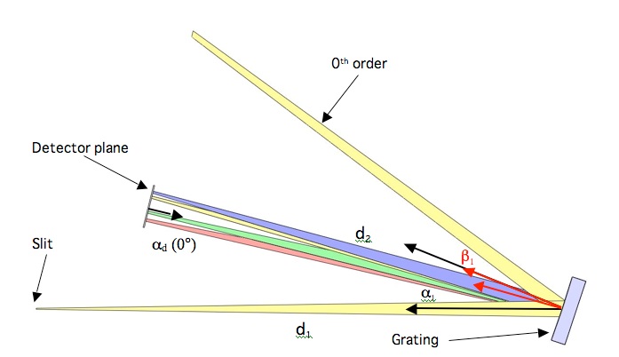

Channel B ranges from 117 to 141 nanometers and reaches a 1.3nm resolution, employing a normal-incidence spectrograph with a 0.6mm wide and 5.0mm tall entrance slit. The B-Channel is responsible for capturing Hydrogen emissions including the prominent Ly-Alpha Hydrogen signal at 121.6nm and different carbon signals.
The spectrometer grating has a line spacing of 2990 per millimeter, uses an Al-MgF2 coating and achieves a 20% efficiency – slightly higher than EUVS-A. The grating is located 25cm from the slit and 20.2cm from the detector. A two-surface filter placed in front of the detector restricts the bandpass to the 117 to 141nm range.
EUVS-B uses a detector similar to the A-channel with 24 pixels placed in four groups to only capture data from the desired lines; masked pixels provide dark current measurements. Pixels of the 140.5nm group are wider than the standard pixels to capture the whole blend of two solar emission lines.
Channel C takes a special role within the instrument and covers a much narrower band from 277 to 283 nanometers with an 0.08nm spectral resolution to resolve the Magnesium II doublet at 280nm. The ratio of the core of the MgII feature is also known as the MgII Index and acts as a tracer for chromospheric activity. Changes in the doublet structure are highly correlated with changes in other chromospheric emission lines.

Because the C-channel of EUVS measures a ratio between two values, it is relatively insensitive to instrumental effects which is why the C channel acts as calibration for the A and B channels.
The optical layout of EUVS-C is similar to the B-channel, but the spectrograph – given its importance for the entire instrument – is fully redundant in design, comprising two independent optical and electrical chains installed in the same optical cavity. EUVS-C employs an interference filter mounted directly in front of a 512-pixel photodiode detector.
EUVS captures data on a number of proxies from which the entire EUV range from 5 to 135 nanometers can be constructed. The instrument measures the intensity of critical solar lines from various parts of the atmosphere that is fed into a model that scales each spectral line to the ones observed from the same region of the atmosphere.

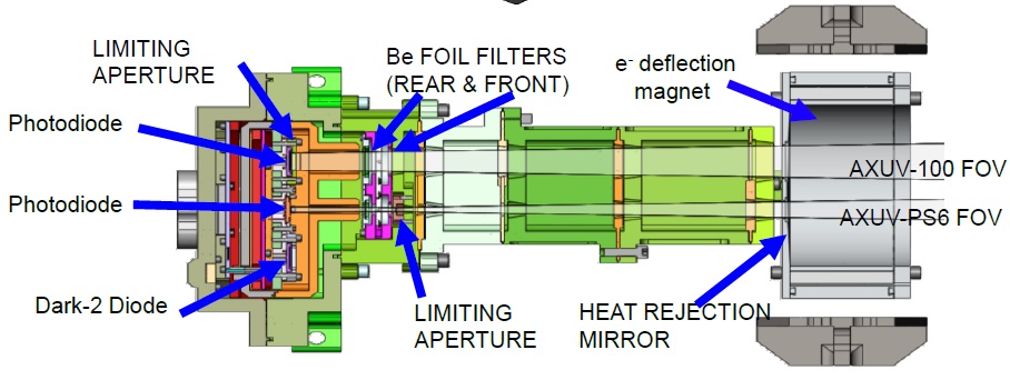
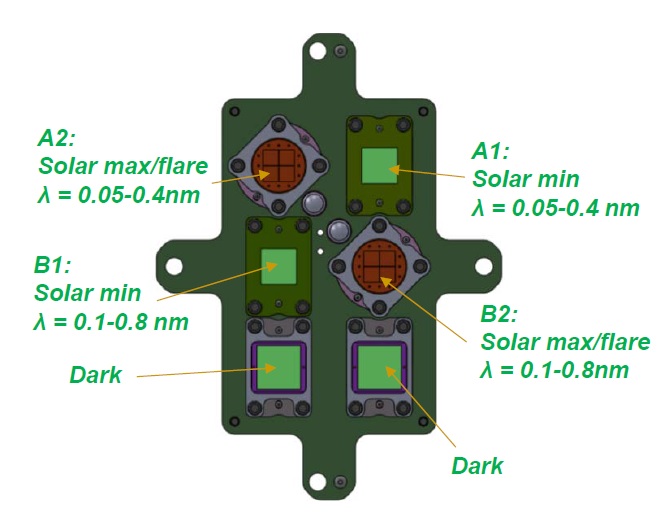
The X-Ray Sensor (XRS) is tasked with the measurement of 0.05 to 0.4 and 0.1 to 0.8-namometer X-Ray bands for monitoring of solar flares to deliver data to predict proton events that can disrupt satellite communications and impact other ground-based systems.
To cover the two wavelength ranges, XRS hosts two channels A & B, each with two photometers with differently sized apertures plus two dark detectors for calibration. The A1 and B1 detectors are optimized for operation during solar minimum with a maximized aperture of 81 square millimeters that allows the instrument to capture the few photons emitted at these wavelengths during quiet solar states. The A2 and B2 channels have a smaller aperture of 4.5mm² that limit the number of photons that are detected during solar maximum.
A major challenge for XRS was the elimination of off-axis X-ray photons and incoming electrons which can create false signals and high background noise, respectively. To shield the instrument, XRS uses a thick outer layer of aluminum that stops all off-axis electrons and an inner layer of tungsten which absorbs X-rays created as Bremsstrahlung from the electron interaction with the aluminum. Electrons arriving along the instrument’s optical axis are diverted by a strong 800 Gauss magnet assembly that is 5cm in length and removes on-axis electrons up to an energy of 5MeV. The outer shielding protects the instrument from off-axis protons while on-axis energetic protons mostly pass through the thin detectors without being absorbed.
XRS has a field of view of +/-70 arcmin taking into account the solar X-ray diameter of +/-27arcmin, the satellite pointing margin of +/-5arcmin and +/-25 arcmin for internal misalignments of the photometer boresight.
The two Solar-MIN channels have an aperture size of 9 x 9 millimeters and use 10 x 10mm silicon photodiodes while the Solar-MAX channels employ 2.1 x 2.1mm apertures and 7.6mm diameter quad photodiodes which can be used to pin-point the location of solar flares on the disk of the sun with sufficient accuracy. XRS-A, covering 0.05 to 0.4 nanometers, uses 50-micrometer thick diodes with 60-micrometer Beryllium filters to define the long-wave cutoff. The B-channels use the same diode thickness but wider 500-micrometer Be filters.
Space Environmental In Situ Suite
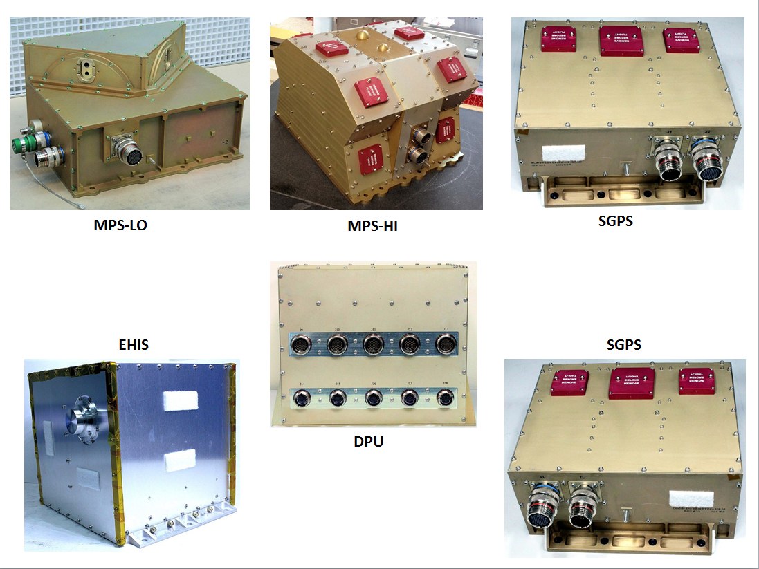
SEISS the Space Environmental In Situ Suite comprises four different instrument packages to measure the particle and electromagnetic environment in Geostationary Orbit, notably trapped electrons/protons, electron flux, proton flux, heavy ions of solar and galactic origin.
Information provided by SEISS is critical for assessing the electrostatic discharge risk and radiation hazards to orbiting satellites and astronauts currently in space. SEISS can warn of high-flux events that could interrupt communications and other satellite services.
The entire SEISS payload has a mass of 74 Kilograms and requires 53 Watts of electrical power, housing a single Data Processing Unit that supports all four sensor units and delivers instruments data to the spacecraft for downlink.
The Energetic Heavy Ion Sensor (EHIS) measures heavy ion fluxes in Earth’s magnetosphere to deliver a complete picture of the energetic particles that are either trapped in Earth’s magnetosphere or arriving directly from the sun or cosmic rays. The instrument can measure ions from Hydrogen through Nickel at energies of 10 to 200 MeV/nucleon. It makes use of the Angle Detecting Inclined Sensors (ADIS) technique to achieve single-element resolution by determining the incidence angle with a simple telescope design of six different silicon solid state detectors.
EHIS has a mass of 9.2 Kilograms and incorporates three principal components – an enclosure, the telescope and four linear boards in charge of power supply and signals processing. The instrument is pointed to the -Z (Anti-Earthward) direction and collects data on a five-minute cadence.
The ADIS system employs three thin 50-micrometer detectors – a circular detector and two oval detectors inclined 30 degrees, three logical detectors 1500-micrometers thick and a single detector that flags penetrating particles.
Two Magnetospheric Particle Sensors are part of SEISS – MPS-Low and MPS-Hi. Both are tasked with measuring the electron and proton flux with the 7.7-Kilogram Lo sensor covering the 30 Electronvolt to 30keV range and the 13kg Hi sensor covers the 50keV to 4 MeV range for electrons and 80 keV to 12MeV for protons. Both instruments take readings at a one-second cadence.
Low-energy electrons are responsible for spacecraft charging which can cause electrostatic discharge and arcing between differently charged components – a condition that can cause permanent damage or inhibit the operation of sensors. High-energy electrons/protons can penetrate a satellite’s structure can cause harm to electronics which can result in a shorter satellite lifetime.
The Solar and Galactic Proton Sensor (SGPS) delivers data for solar storm warnings by measuring protons at energies of 1 MeV and 500 MeV, coming from the sun and galactic origins. It consists of two sensor heads pointed to the + and -X directions.
Magnetometer
The GOES-R-class Magnetometer is provided by Lockheed Martin under the base GOES contract and delivers measurements of the local magnetic field at the GEO location of the satellite. Knowledge on the magnetic environment of Earth is important since it drives charged particle dynamics in the magnetosphere.
Magnetometer products are an integral part of space weather prediction but also find application in research.
The GOES magnetometers are the first instruments to detect when a significant space weather event reaches Earth. Magnetic activity signatures can be used to identify and forecast the severity of space weather events
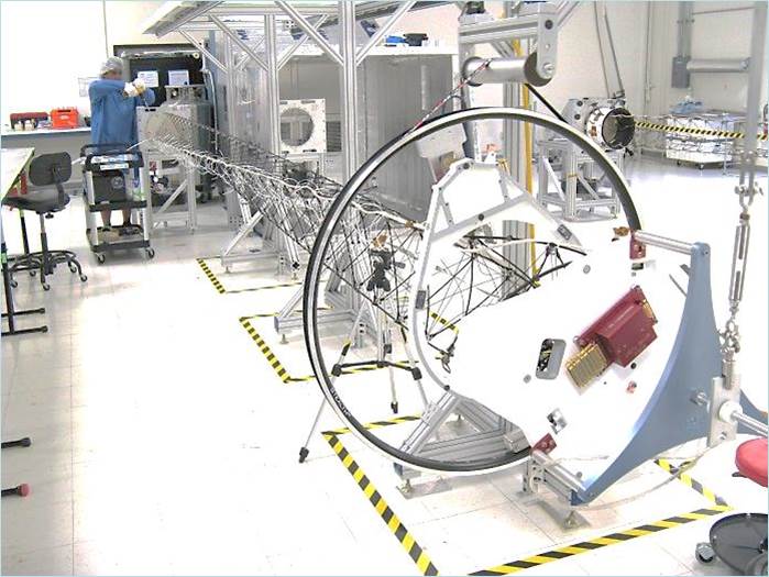
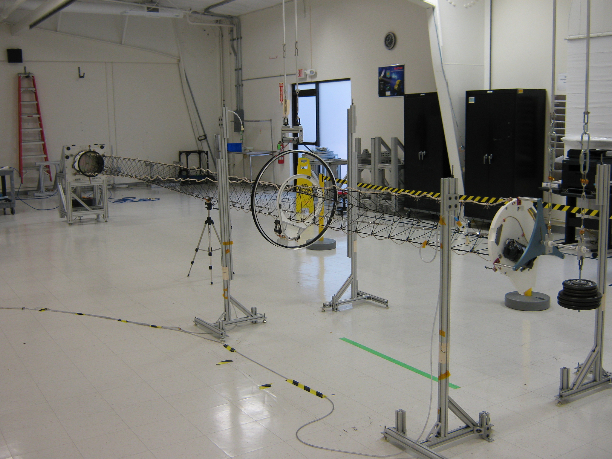
The Magnetometer resides on an eight-meter long boom deployed from the spacecraft once on station in Geostationary Orbit to place the sensitive sensor as far away as possible from the spacecraft’s own magnetic field created by the onboard systems. To further eliminate the influence of the S/C magnetic field from measurements, MAG consists of a pair of Fluxgate magnetometers – one on the tip of the boom, the other further inboard to yield measurements of the spacecraft’s magnetic influence to be subtracted from the measurement data.
The overall principle of the two fluxgate sensors is identical – making use of the nonlinearity of magnetization properties for the high permeability of easily saturated ferromagnetic alloys to serve as an indicator for the local field strength. The ferromagnetic material is surrounded by two coils of wire – one coil runs an alternating electrical current which drives the core through an alternating cycle of magnetic saturation. This changing field induces a current in the second coil which can be measured by a detector.
In a magnetically neutral environment, the input and output currents would be identical, but the presence of an external field leads to an easier saturation of the core when in alignment with the core while saturation is less easily achieved when the core is exposed to an opposing field.
This leads to the output current becoming out of step from the input which, with the known parameters of the core material and the simultaneous measurement of the input, will provide information on the local field strength using known calibration data.
The GOES magnetometer as a sensitivity of 0.1 nano-Tesla, a resolution of 0.01nT and a range of +/-1000nT. Ten samples are taken per second, but onboard processing downsamples the data to a frequency of 2.5 Hz. Data products from the MAG instrument are field vectors in seven different coordinate frames, magnetopause crossing identification and pitch angle measurements for the SEISS suite.
The Magnetometer has a mass of 25 Kilograms, including the deployable boom.