
Trace Gas Orbiter – Instrument Overview

The ExoMars Trace Gas Orbiter is a joint effort between the European Space Agency and Roscosmos to investigate trace gases in the Martian Atmosphere which are of importance when searching for biosignatures or geological processes, past or present.
Per the agreement between ESA and Roscosmos, the TGO spacecraft is provided by ESA and the Proton rocket is supplied by Roscosmos while both partners each develop two instruments.
Amounting to 112 Kilograms, TGO carries four instruments designed to detect trace gases with an improved accuracy of three orders of magnitude compared to previous measurements made from orbit and telescopic observations.
TGO sets out to carefully track spatial and temporal variations of trace gases which are known to be quite significant. Goals of the mission are to identify sources and sinks of atmospheric trace gases.
The Trace Gas Orbiter will characterize the Martian atmosphere with respect to the distribution of trace gases, looking at geographical variations and changes over small time scales as well as seasonal variations.
TGO will take a detailed inventory of the Martian atmosphere, identifying what trace gases are present and studying their isotopes. The instruments will be able to map the Deuterium-to-Hydrogen ratio to deliver additional data on atmospheric escape and water reservoirs. Additionally, TGO will gather data on atmospheric temperatures, suspended aerosols, water vapor and ozone, also studying atmospheric circulations and flow patterns.
TGO will collect imagery of the surface to tie phenomena observed in the atmosphere to sources or sinks on the ground. Mapping of subsurface Hydrogen will yield a map of hydrogen distribution across the planet at a resolution ten times better than previous measurements.
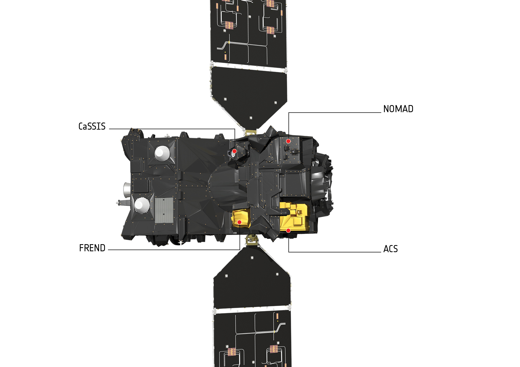
The Trace Gas Orbiter carries the following instruments:

NOMAD – Nadir and Occultation for Mars Discovery:
NOMAD comprises three spectrometers, two sensitive for infrared and one for ultraviolet wavelengths, to identify atmospheric components such as methane and hydrocarbons via solar occultation measurement and by studying radiation reflected by the Martian atmosphere. NOMAD was developed at the Institute for Space Astronomy in Belgium.
ACS – Atmospheric Chemistry Suite:
ACS includes three infrared instruments to look at the chemistry and structure of the Martian atmosphere, complementing NOMAD in the infrared wavelengths and by taking reference images of the sun to be used in occultation measurements by NOMAD. The instrument was developed at the Space Research Institute (IKI) in Russia.
CaSSIS – Color and Stereo Surface Imaging System:
CaSSIS is tasked with delivering images of the Martian Surface to be used in conjunction with atmospheric data to identify sources and sinks for trace gases such as Methane which is known to be present in certain geological locations while not being detected in other areas. The instrument is comprised of a high-resolution camera reaching a ground resolution of 5 meters per pixel for color and stereo imaging across a wide ground swath. CaSSIS was built at the University of Bern, Switzerland.
FREND – Fine Resolution Epithermal Neutron Detector:
FREND, developed at the Space Research Institute (IKI) in Russia, is responsible for the detection of subsurface hydrogen to a depth of one meter to uncover water-ice deposits near the surface. Measurements of subsurface water and OH by FREND will be ten times better than previous missions.
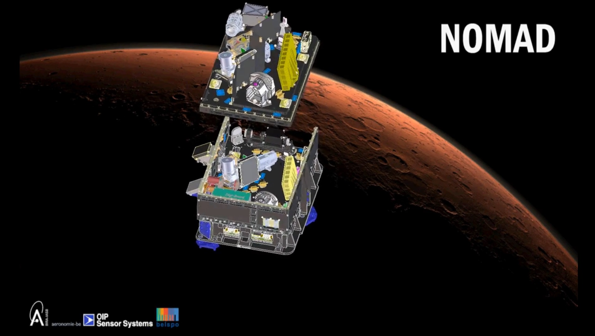
NOMAD
NOMAD, the ‘Nadir and Occultation for MArs Discovery’ is a core instrument of the Trace Gas Orbiter as it is responsible for the detection and quantification of trace gases within the atmosphere by their spectral emissions.
The NOMAD instrument can measure the spectral emissions from the atmosphere across a wide spectral range covering the ultraviolet, visible and infrared bands through the use of three separate spectrometers. Given its broad spectral coverage and high resolution, NOMAD can detect the components of the Martian atmosphere even at trace concentrations.
NOMAD will make its measurements in solar occultations – pointing towards the sun when the atmosphere of Mars is in the line of sight between the instrument and the sun, allowing atmospheric gases to absorb solar radiation and the instrument to record the resulting spectrum. The other operational mode looks directly nadir (down towards the planet) to analyze sunlight reflected by the surface and atmosphere.
The instrument covers the ultraviolet and visible bands at wavelengths of 200 to 635 nanometers and the infrared range from 2.2 to 4.3 micrometers.
Three modes of operation can be supported by NOMAD:
In Solar Occultation Mode, the instrument observes six limited areas of its spectral coverage band each second to target specific molecules absorbing at different wavelengths while keeping a high signal to noise ratio for each measured species.
Each solar occultation lasts approximately five minutes, yielding 300 spectra at each wavelength. As the sun moves up or down behind the atmosphere as seen from the spacecraft, a profile can be created from the very top of the atmosphere down to near-ground altitude to deliver valuable data on the concentration of specific compounds at certain atmospheric altitudes.
The Limb, Nadir and Occultation Mode is chosen when light levels are low, looking to the instrument nadir, directly towards the Martian surface. This mode delivers a full picture of atmospheric composition while also examining the surface, looking for ices. This operational mode will be active every three to four sols with varying local times across the planet to track changes in overall atmospheric composition on a diurnal cycle as well as long-term variations with changing seasons.
The Ultraviolet and Visible Mode collects spectra every second for the VIS/UV channel, delivering data on gases that are of particular interest – Methane, sulfuric acid and atmospheric aerosols.
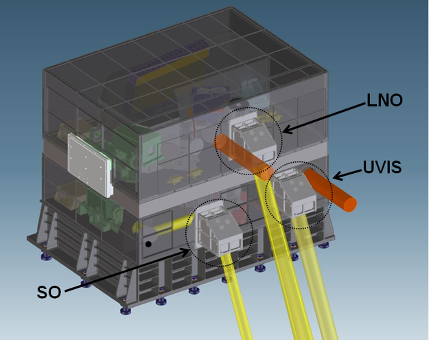
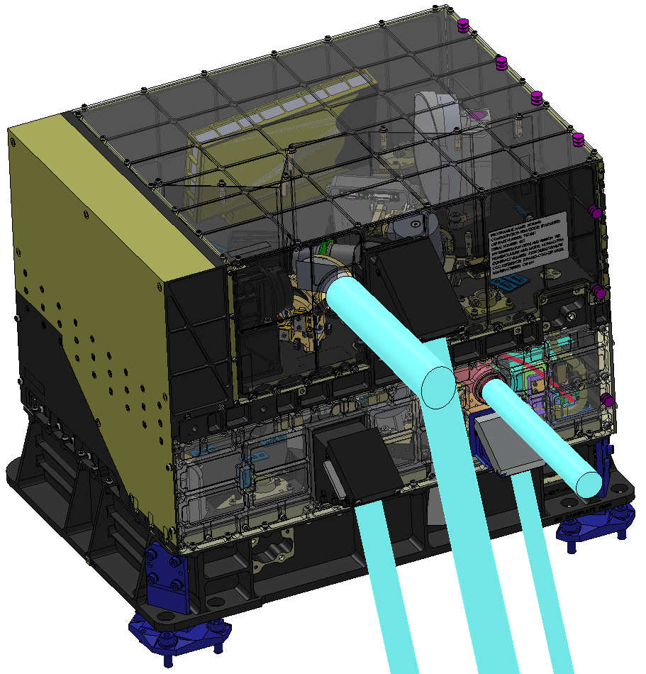
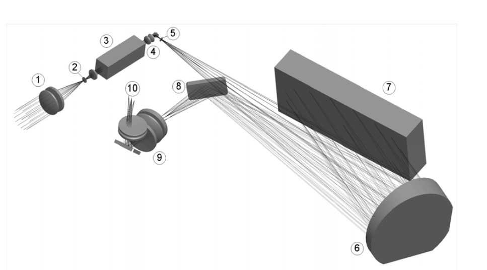
The Solar Occultation (SO) channel operates at wavelengths between 2.2 and 4.3 micrometers making use of a Littrow-type spectrometer. The incoming light is passed through entrance optics and an Acousto-Optical Tunable Filter that selects the wavelength window to be observed. After passing through the AOTF, the radiation enters the spectrometer through the entrance slit onto a primary mirror passing the light to an Echelle grating with 4 lines per millimeter, acting as the dispersive element of the instrument. The light reaches the detector through the collimating and folding optics.
An AOTF (Acousto-Optic Tunable Filter) is an electro-optical device that serves as an electronically tunable spectral bandpass filter with no moving parts. It uses a crystal in which Radio Frequency Waves are used to separate a single wavelength of light from a broadband source. The output wavelength is a function of the RF frequency that is applied to the crystal which can be varied.
Usually, an oscillating electrical signal is used to drive the piezo-electric transducer that vibrates to create acoustic waves in the crystal which change the index of refraction of the material so that incoming light scatters. (The crystal lattice is alternately compressed and relaxed which allows the medium to act like a diffraction grating but with the advantage of only diffracting one specific wavelength that is selected by altering the RF.)
Within the spectrometer, the AOTF acts as the selector for the spectral window to be observed. This design provides a number of advantages including long-term wavelength repeatability, extremely high wavelength purity, fast response to RF changes so that spectra can be recorded within seconds, high efficiency and long service life (no moving parts).
SO selects narrow spectral windows of 20 to 30 cm^-1 depending on the chosen diffraction order. The instrument’s detector is an actively cooled Mercury-Cadmium-Telluride focal plane array comprised of 320 columns of pixels (spectral direction) and 256 rows (spatial direction). The focal plane is kept at a constant temperature between 80 and 100 Kelvin.
The Limb, Nadir and Occultation channel (LNO) uses an identical design to SO – AOTF, Echelle spectrometer, cooled HgCdTe detector. LNO measures in the wavelength range between 2.2 and 3.8 micrometers. The LNO channel is fed by two telescopes, one viewing nadir and one directed to the limb – the view is selected by a flip mirror directing radiation into the spectrometer.
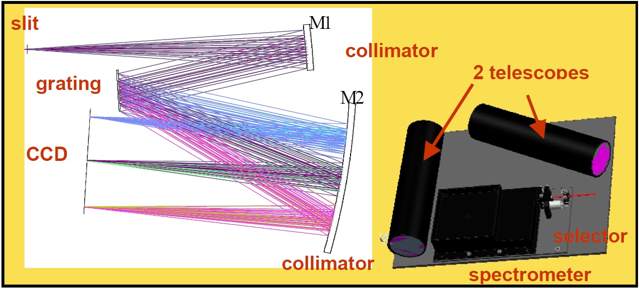
The UVIS (Ultraviolet and Visible) channel hosts a pair of telescopes feeding a common spectrometer. One of the telescopes is positioned to view a sector directly to the spacecraft nadir while the other is placed for occultation and limb observations to deliver overlapping data with both of the other instruments. UVIS covers the UV and Visible wavelengths from 200 to 650 nanometers.
The two telescopes focus the light onto the entrance slit of the spectrometer and the M1 primary mirror reflects the light onto the diffractive grating, separating the individual wavelengths and passing the radiation to the M2 collimator that focuses the dispersed light onto the Focal Plane Assembly hosting a Charged Coupled Device Detector.
With SO and LNO, up to 12 different wavelength intervals can be selected to be measured in one second, creating a 160-millisecond accumulation time for each spectral interval. The two channels have an instantaneous field of view of 1 x 10 Kilometers constrained by the size of the solar disk and the entrance slit dimensions. This allows the two instruments to make scans of one Kilometer slices of the atmosphere, creating a high-resolution vertical profile with each occultation and limb measurement. For UVIS, a 1 x 1-Kilometer slice is observed every 0.25 seconds, creating a vertical sampling distance of under 300 meters.
In Nadir Mapping Mode, NOMAD measures vertical columns of 3 x 12 and 5 x 6 Kilometers for high- and low-resolution LNO measurements and 8 x 5 Kilometers for UVIS. Carbon Dioxide column abundance is measured to be incorporated in data processing to account for topography and surface shadowing when determining the functional column densities of trace gases.
NOMAD will cover Martian latitudes between 87°N and 88°S for occultation measurements with good revisit times. Nadir coverage between +/-74° latitude will deliver a global revisit time of 3 to 4 sols with varying local times. Given the geometry of the orbit, some ground tracks will be repeated, leading to better temporal coverage over certain areas.
ACS – Atmospheric Chemistry Suite
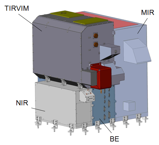
The ACS combines three spectrometers covering the near-infrared, mid-range infrared and thermal infrared wavelengths to gather data on a variety of atmospheric constituents and study the structure of the atmosphere and photochemical processes ongoing therein.
Not unlike the NOMAD instrument, ACS makes use of solar occultation measurements with the atmosphere between the instrument and the sun to gather data at sunrise and sunset. Nadir and limb measurements are also supported by the instrument.
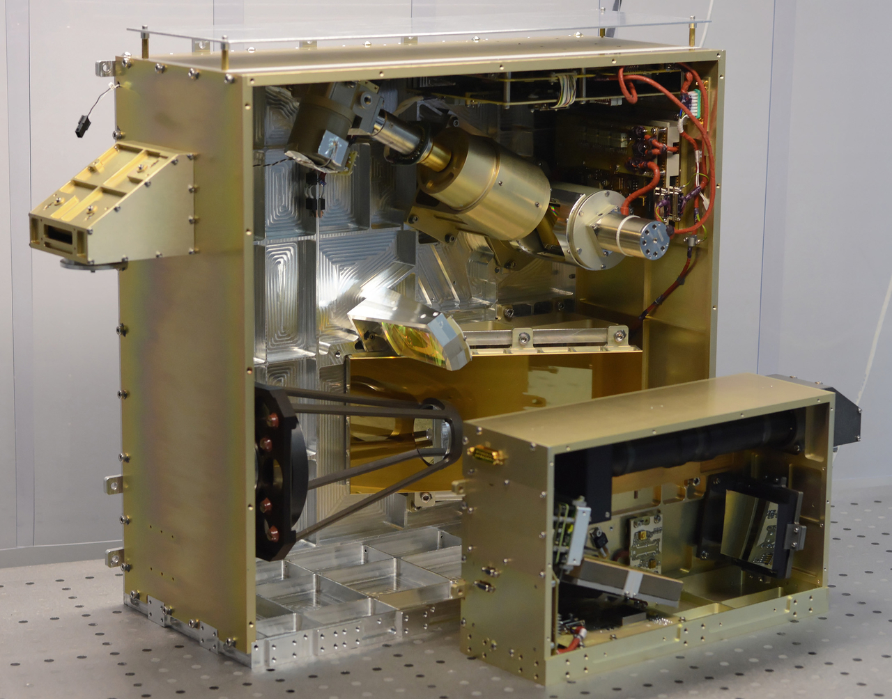
The ACS instrument consists of the three spectrometers and a common electronics box for a total mass of 33.5 Kilograms fitting into an envelope of 52 x 60 x 47 centimeters. The instrument requires between 39 and 85 Watts of electrical power during operation and generates 1.5Gb of data per day.
The ACS-NIR instrument makes use of an Echelle-Acousto-Optic Tuneable Filter (AOTF-TeO2) spectrometer (see NOMAD for more details on this type of arrangement and purpose of the AOTF) capable of precise spectral measurements. It supports nadir, limb, and solar occultation measurements across a wavelength range of 0.73 to 1.7 micrometers with a red filter at the instrument entrance to block any sun wavelengths shorter than 0.7 micrometers.
The NIR instrument employs a Littrow Auto-Collimator scheme in which an off-axis parabolic mirror is used simultaneously as the collimating and imaging elements – passing light from a 4 millimeter by 40-micrometer entrance slit onto the grating and reflecting dispersed radiation to the detector assembly.
The NIR Echelle grating has a 70° blaze angle and 24 grooves per millimeter, supported on a Zerodur substrate. NIR’s parabolic mirror serving as imaging mirror and collimator has a focal length of 20 centimeters and is manufactured from aluminum alloy and coated with copper.
The focal plane assembly hosts an actively cooled Indium-Gallium-Arsenide pixel array of 640 columns and 540 rows. The instrument can be programmed to sequentially step through ten diffraction orders, requiring the AOTF to complete ten different tunings per measurement cycle with exposure times between 1ms to 1s. This allows the instrument to cover ten narrow wavelength bands within the 0.73-1.6-micrometer range.

NIR has an instantaneous field of view of 20 by 0.02 arc-min and achieves a spectral resolution of 16 nanometers. When operated in Nadir Mode, the instrument collects one spectrum every two seconds while spectra are created every 50 milliseconds in limb and occultation mode.
Although NIR is the smallest of the three ACS instruments, weighing in at 3.3kg, it provides vitally important measurements addressing many scientific goals. NIR delivers the water vapor mapping in nadir and H20 vertical profiling in limb/occultation mode in the 1.38-micron band with a measurement accuracy 100 times better than heritage instruments. Water vapor profiles will be measured from 10 to 80 Kilometers in altitude.
The instrument also observes oxygen at 1.27 micrometers with special focus on dayglow for indirect ozone measurements and nightglow as a tracer for oxygen recombination. O2 vertical profiles will be measured up to 40 Kilometers in the 760nm band.
In combination with MIR, the instrument will measure carbon dioxide density profiles and characterize atmospheric aerosols, their density, particle sizes and whether they are ices or solid particles.
Passing over the night side, NIR nadir measurements will look at OH airglow and NO signatures, never attempted at this sensitivity before.
The MIR instrument also uses an Echelle-type spectrometer. Radiation is reflected by a folding mirror and passes through a focusing telescope to form the image of the solar disk that is then delivered to the 30-micrometer spectrometer entrance slit from where it is passed to the Echelle diffraction grating via a pair of mirrors. Next in the optical path is the collimator and two steerable secondary gratings with their own collimator delivering the dispersed radiation to focusing lenses, a cold filter and onto the detector array.
The gold-coated primary Echelle grating has three grooves per millimeter and operates at a blaze angle of 63.43 degrees, measuring 10.7 by 24.0 centimeters in size. The MIR detector is comprised of a Mercury-Cadmium-Telluride array with 640 columns in the spectral direction and 512 rows in the spatial direction. The focal plane assembly is actively cooled by a mechanical cooler to limit dark currents and a bandpass filter with a 2.4 to 4.2-micrometer pass is placed atop the detector.

The secondary cross-dispersion diffraction gratings have 180 and 361 grooves per millimeter, respectively, and are controlled by a stepper motor. This allows the instrument to switch from one group of diffraction orders to another or alternating two positions during a measurement sequence. The gratings are moved at steps of 1.8°, meaning that 10 to 30 Echelle orders are available for recording.
MIR has a field of view of 10 by 0.5 arc-min and covers an instantaneous spectral range of seven windows 0.28 to 0.32-micrometers wide, collecting one set of spectra every 0.5 to one second, only operated in Solar Occultation mode. This measurement technique permits the instrument to maximize the number of gaseous species detected simultaneously
The MIR instrument covers several important Carbon Dioxide absorption bands to make measurements of CO2 density and temperature profiles from 10 to at least 140 Kilometers, also looking at isotopic ratios of CO2. MIR also measures the Hydrogen-to-Deuterium ratio which is the most important tracer for atmospheric loss processes. With its occultation measurement technique, MIR can measure the vertical profile of D/H which has not been done before and hoped to deliver new information on water reservoirs and atmospheric cloud formation.
Methane, one of the major scientific goals of the TGO mission, will be detected with a low threshold of 0.3 parts per billion at the 3.18-3.45-micrometer wavelength making use of Echelle diffraction orders 187-173. MIR also covers bands for Carbon Monoxide to be used to understand airmass transport and the instrument will be employed to search for minor constituents including hydrocarbons, hydrochloric acid, sulfuric compounds and other species.
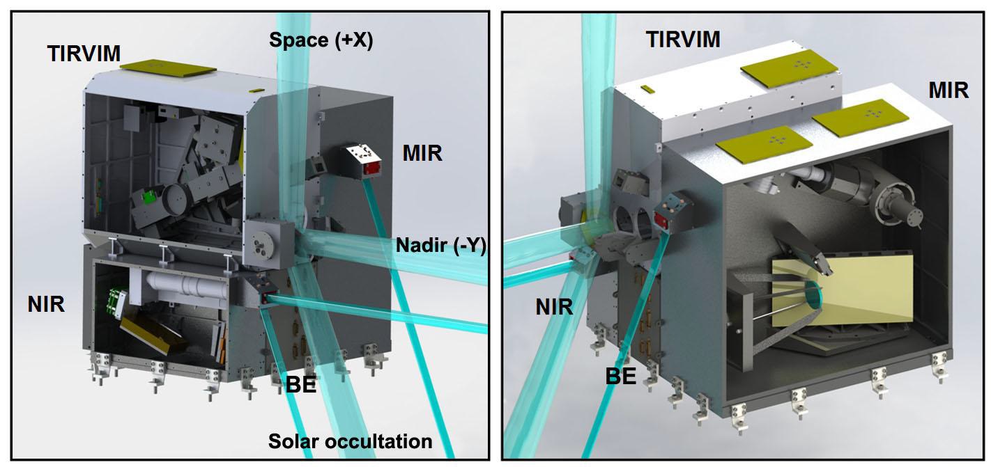
The TIRVIM instrument (Thermal Infra-Red V-shape Interferometer Mounting) is a Fourier-transform spectrometer covering a wide spectral area from 2 to 17 micrometers. TIRVIM is a two-inch double pendulum Fourier-Transform (FT) spectrometer with a total mass of 11 Kilograms, primarily tasked with the measurement of atmospheric temperature and aerosols in nadir-looking mode. The instrument combines three different detectors fed by a common interferometer featuring a KBr beam splitter.
A 85 x 60-millimeter scanning mirror outside the spectrometer assembly selects the field of view, sweeping out a 270-degree sector around the Z-axis and covering the nadir sector while also passing over a blackbody calibration source. Entering the Optical Module, the radiation is directed through a nadir inlet window to the interferometer.
A separate optical path directs sunlight through a periscope offset by 67 degrees to be able to make direct solar observations. Sunlight passes a sun-inlet filter and is folded onto a path towards the interferometer.
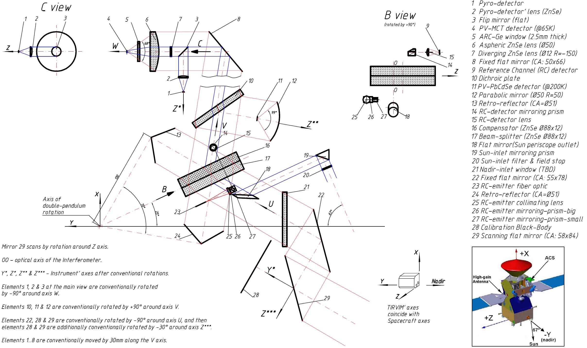
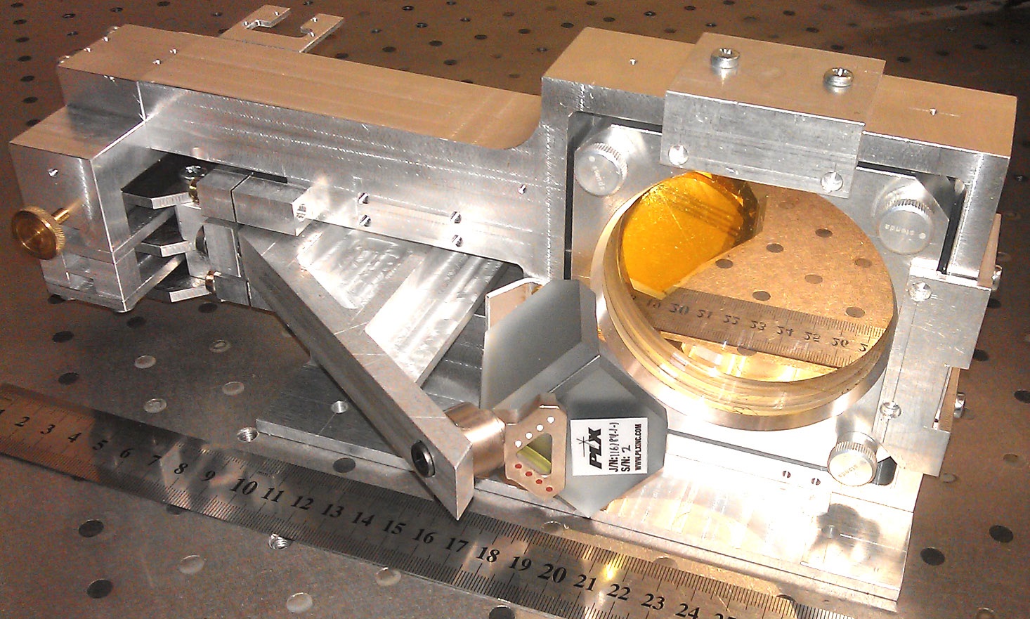
The heart of the TIRVIM instrument is the interferometer with a double-pendulum arm length of 13 centimeters, a KBr beam splitter and compensator 8.8cm in diameter and 12mm thick. A reference channel is created by a laser diode operating at a wavelength of 760 nanometers measured by a Silicon photodiode detector.
The radiation is directed to one of three detectors by a three-position flat mirror. TIRVIM hosts a Mercury-Cadmium-Telluride detector sensitive in a long-wavelength range of 1.7 to 17 micrometers with a germanium inlet window to block any short wavelengths. The focal plane is cooled to 65 Kelvin by a Stirling cooler coupled to an external radiator.
A short-wave detector covers the 2 to 3.5 μm range, also cooled by the Stirling machine.
Finally, a pyroelectric detector delivers measurements up to a wavelength of 25 micrometers dedicated primarily to water vapor detection at nadir. This detector operates at ambient temperature.
The TIRVIM instrument covers the entire wavelength range of the MIR instrument. Though operating at lower resolution, the instrument can act as backup for MIR and deliver data useful for MIR measurement validation. TIRVIM also addresses additional science objectives such as the thermal sounding in the 15 μm CO2 band. The instrument can make measurements of silicate dust and water ice and it covers strong absorption bands of ozone and hydrogen peroxide, not recorded by any other instrument.
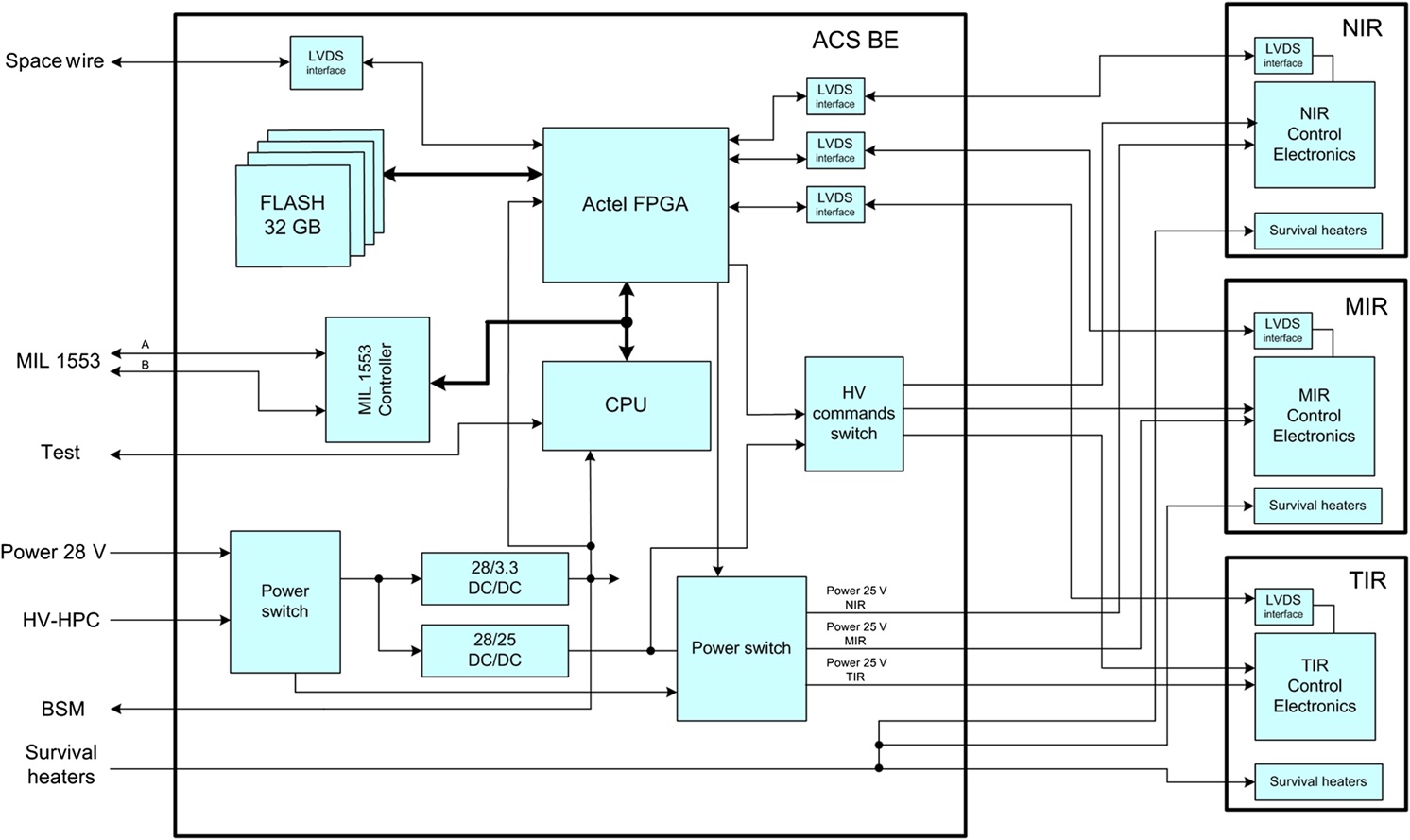
Each of the three instruments delivers raw data through a LVDS interface to the common Electronics Unit which exists twice for redundancy. The Electronics Block accepts the raw signals that are processed by a Field Programmable Gate Array and delivered to a 32GB flash memory for storage. All instrument functions are controlled by a Central Processing Unit, accepting commands from the spacecraft, delivering status telemetry and controlling all instrument components and operational modes.
The Electronics Block includes DC-to-DC voltage converters and local regulators to deliver the required voltages to the various instrument components. Payload data is relayed to the Payload Data Handling Unit via a SpaceWire bus while telemetry and commands are exchanged via a 1553 line.
Due to limitations in data downlink volume, ACS can not operate for every solar occultation since each generates 500Mbit per data and the upper limit for daily data volume created by the instrument is only 1500Mbits that has to account for nadir and occultation observations.
CaSSIS – Color and Stereo Surface Imaging System
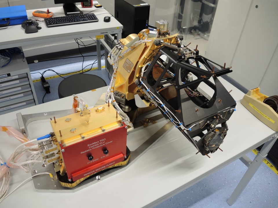
CaSSIS is the only optical imager of the Trace Gas Orbiter mission, delivering high-resolution color and stereo photography of sites of interest in search of sources and sinks of atmospheric trace gases. These may be sites of sublimation, erosion processes and volcanism. CaSSIS will also be employed to identify potential landing sites for the 2018/2020 rover mission.
High-resolution imagery of the surface will allow scientists to investigate geological processes that may be responsible for the release of gases into the atmosphere and their elimination from the gaseous phase. CaSSIS achieves an image resolution of five meters and stereoscopic reconstruction will yield a vertical resolution on the order of six meters.
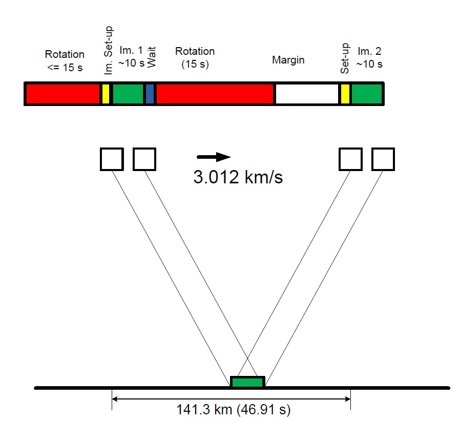
Because the Trace Gas Orbiter normally rotates around the yaw axis to keep the solar arrays pointed at the sun and the thermal radiators to deep space, CaSSIS has to employ a rotation system to turn the telescope in order to compensate for the orbiter’s rotation – keeping the image rows perpendicular to the spacecraft ground track. This will also permit stereo imaging – first rotating the telescope to point to a target 10 degrees in front of the spacecraft, then rotating it 180° to point 10° behind the vehicle to image the same location and obtain a correlated stereo pair.

The acquisition of stereo pairs with minimal temporal difference between two frames yields images at the same illumination. Nominally, the time between stereo points will be 47 seconds, requiring a 180-degree rotation of CaSSIS in around 15 seconds. The mechanism uses a stepper motor with ceramic bearings driving a worm gear via a bellow-type bearing. All gear components are made of titanium alloys for maximum strength.
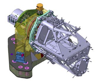
The CaSSIS telescope has a 135-millimeter aperture and employs a three Mirror Anastigmat optical design with a total field of view of 1.34 x 0.88 degrees covering an 8-Kilometer ground swath. The Three Mirror Anastigmatic design was chosen since it provides a larger field of view than the conventional Cassegrain or Ritchey-Chrétien systems. CaSSIS uses Carbon-Fiber Reinforced Plastic for all structural components given its low thermal expansion, keeping the optical components in perfect alignment. The mirrors use a space-qualified silver coating with very little optical distortion.
The CaSSIS telescope has a focal length of 880 millimeters, focusing an image onto a CMOS detector of 2048 x 2048 pixels using a 10-micrometer pixel pitch. Readout is accomplished in a snapshot operation at a rate of 5 Megapixels per second with a 14-bit depth.
CaSSIS covers four wavelength areas – a wide panchromatic band centered at 650 nanometers with a 250nm bandwidth, an infrared band at 950nm (150nm bandwidth), a near-infrared band at 850nm (120) and a blue-green channel at 475nm (150).
Typically, CaSSIS operates in a push-frame mode where 2048 x 256-pixel images are collected at a repetition rate matching the spacecraft ground-track velocity in order to build image-strips along the surface.
The Proximity Electronics in charge of detector read-out are installed inside the rotation bearing and connected to the instrument electronics box via a dedicated cable system with semi-rigid cables to support the rotation of the telescope. The Electronics Unit is comprised of a Digital Processing Module and power conversion equipment. The DPM accepts the analog detector read-out that is converted to digital data by a dual-core LEON processor.
CaSSIS has a data volume allocation of 2.9Gbit per day, equivalent of up to eight stereo pairs per day plus additional single-frame images.
FREND – Fine Resolution Epithermal Neutron Detector
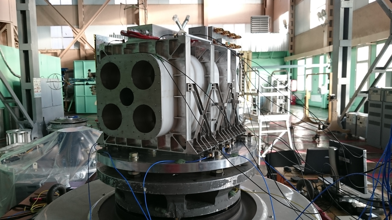
The FREND instrument is a neutron detector coupled to a collimation module to narrow the field of view for the generation of high-resolution maps of subsurface Hydrogen. The instrument collects neutrons from the Martian surface that are generated by the continuous bombardment of cosmic rays interacting with the surface and subsurface material and releasing neutrons which can be registered and, according to their energy, will reveal the hydrogen concentration in the surface (the primary driver of neutron energy).
FREND is comprised of the collimator and a dosimeter module to perform its measurements in a 10-degree field of view to generate a spatial resolution of 40 by 40 Kilometers, ten times better than existing maps. The instrument features two neutron detectors – a Helium-3 counter system covering energies of 0.4 electron-volt to 500keV, and a Fast Stylbene Scintillator sensitive in the high energy region from 0.5 to 10 MeV.
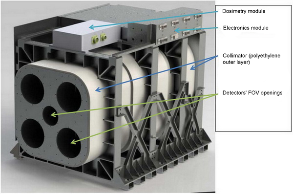
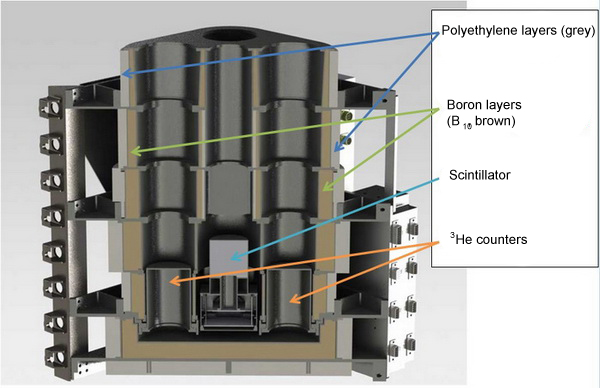
The Collimator assembly is a passive element, encasing the five detector assemblies. It is comprised of two layers, the outermost consists of dense polyethylene and the inner using a Boron-10 powder. Containing a high-hydrogen content, the polyethylene slows incoming neutrons down so that the Boron can absorb them, preventing any neutrons from striking the detectors unless they pass through the narrow openings in the collimator material.
Four Helium-3 detectors are filled with Helium-3 gas at a pressure of 6 bar and positioned in the four openings of the collimator assembly. Within the Helium-3 gas, neutrons at thermal energies trigger a reaction yielding two charged particles (tritium and protium) which create a charge cloud that can be sensed with ionization detectors.
The Stylbene Scintillator uses an organic crystal of Sylbene/Stilbene which can convert neutrons into photons that are then detected by optical instruments such as photomultipliers. Through pulse shape discrimination, events caused by gamma-rays and neutrons can be separated and shielding is employed to avoid signals triggered by particles coming from deep space.
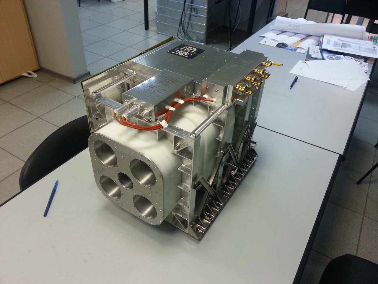
FREND has a mass of 36 Kilograms and is 46.5 by 38.0 by 37.0 centimeters in size, requiring 14 Watts of power for operation. It typically collects data over a one-second integration time.
A separate Dosimetry Module is installed atop the collimator assembly to measure the flux, absorbed dose and dose intensity from cosmic rays and ionization loss spectra to yield linear energy transfer spectra in human tissues to determine the equivalent dose of cosmic radiation that would be encountered by a human. The Dosimetry Instrument will be active for the entire mission, measuring the radiation environment during cruise and in orbit around Mars.
The Liulin-MO dosimetry instrument is comprised of two separate telescopes with two semiconductors each. The dosimeter’s energy resolution is around 100keV across an energy band of 100 keV to 8 MeV and 350keV for the 8 to 70MeV range.
FREND’s primary goal is to map the content of hydrogen in the upper layer of Martian regolith to a depth of 1.5 meters with a spatial resolution of 40 Kilometers. Data will be used to compare neutron fluxes from the Martian surface in different seasons and under different solar activity.
The Dosimeter will measure the radiation environment during the cruise to Mars and in orbit, looking at the distribution of electrons, protons and HZE-particles (high atomic number and energy).