Schiaparelli Lander Instrumentation Overview

The Schiaparelli lander hosts a number of sensors and instruments that can be divided in the EDM Surface Payload and the EDM Entry and Descent Science Package only active during the critical landing sequence which is the prime demonstration objective of the mission.
The lander has been named after 19th century astronomer Giovanni Schiaparelli who conducted an extensive study of the features of Mars. EDM carries a small science payload comprised of an environmental and meteorological sensing system, and a descent camera. Only powered by non-rechargeable batteries, the lander will operate for about four sols on the Martian surface.
Originally, the Schiaparelli lander was to carry a more advanced sensor complement, referred to as the Humboldt payload with eleven instruments. However, in 2009, the lander design was de-scoped, canceling the Humboldt sensor suite. In its initial design, EDM was to be outfitted with a radioisotope thermoelectric generator to allow the lander to operate for a full year.
The primary objective of Schiaparelli is the landing on Mars. Carrying a number of sensors, EDM will take measurements of the atmosphere, the re-entry environment and the response of the vehicle to the various environments it will go through.
DREAMS

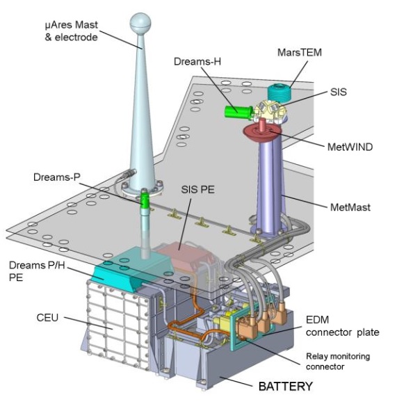
DREAMS is the surface sensor package hosted by the Schiaparelli lander, going by the full name of ‘Dust Characterization, Risk Assessment, and Environment Analyzer on the Martian Surface’.
The payload is comprised of a suite of sensors to measure wind speed and direction (MetWind), pressure (DREAMS-P), temperature (MarsTem), humidity (DREAMS-H), atmospheric opacity (Solar Irradiance Sensor) and electric fields in the atmosphere (MicroARES).
The primary goal of the DREAMS sensor package is to address Mars exploration goals by characterizing the landing site environment during the peak of the dust storm season. Dust in the atmosphere will be measured by the instrument and dust-raising phenomena will be studied to help assess risk posed by Martian dust storms for future crewed missions. Data gathered by DREAMS includes unprecedented parameters such as electrostatic discharges, electrostatic charging, and electromagnetic noise created by dust moving through the atmosphere which can be potentially harmful for communications systems.
DREAMS will make the first ever measurements of the electric field on the surface of Mars which, combined with data on atmospheric dust and wind speed, will deliver insights into the role of electrical forces in dust-lifting and dust storm creation. Dust electrification processes can be studied with data from MicroARES and the humidity sensor.
A global atmospheric circuit is hypothesized to exist on Mars, connecting the surface and ionosphere with charging caused by the interaction of moving dust particles. Electrical charging of the atmosphere may also have some implications on chemical processes and DREAMS is the first instrument to take a closer look to quantify electrical charging and possibly uncover some of its mechanisms.
DREAMS-P and DREAMS-H have been developed by the Finnish Meteorological Institute. The sensors use a heritage design, but the sensor controller, in charge of data processing, has been changed from a radiation hardened to a commercial-off-the-shelf device.
Two pressure sensors and one humidity transducer are installed on the lander, each with eight channels including capacitive measurement channels for pressure/humidity, plus reference temperature channels and constant reference capacitors for calibration. The read-out is accomplished by determining the RC-oscillator frequency of a channel, simultaneously counting sensor and reference block pulses. DREAMS-P is connected to a tube extending upward from the main DREAMS electronics box.
Four of DREAMS’ components are installed on the MetMast, extending up from the lander to place them into the Martian environment. These sensors are Met Wind, SIS, MarsTem and DREAMS-H.
MetWind is a hot film anemometer to make 2D wind measurements – wind speed and direction. It can measure wind speed from 0.3 to 30 meters per second and higher, and achieves an accuracy for wind speed of +/-1m/s and +/-10 degrees for wind direction.
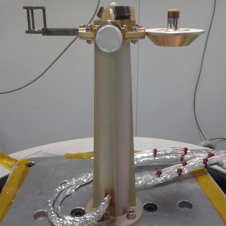
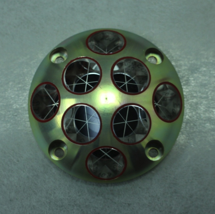
SIS, the Solar Irradiance Sensor, is comprised of an Optical Head and Processing Electronics with the optics sitting atop the MetMast and pointing zenith towards the sky. The Optical Head consists of a truncated tetrahedron with face inclination angles of 60° to reduce the dust deposition on the optical sensors. Each lateral face facilitates a pair of detectors with different optical filters, making them sensitive for the UVA band at 315-400 nanometers and the 700-1000nm Near Infrared Band. The detector elements are photodiodes and collimators are used to shape the field of view of each detector to avoid widening of spectral response at high incidence angles. Sitting atop the collimators is a UG11 filter on the UV channel and a transparent teflon window on the NIR channel.
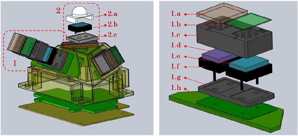
Installed on the zenith-facing panel of the Optical Head is a Silicon detector tasked with monitoring the total luminosity across a broad wavelength range of 200-1100nm. A diffusing element sits atop the Si detector to limit the impact of sun position on detector output.
This optical design will allow one detector pair to receive direct sunlight plus diffuse light while the others only receive diffuse light, allowing for a differentiation between them. Directly underneath the detectors are pre-amplification electronics to deliver signals to the Electronics Unit. Four circuit boards on the optical head provide power filtering, multiplexing of data, and buffering. A platinum resistor is used to measure the temperature of the optical head and a blind photodiode acts as a reference.
The Electronics of the SIS instrument are based on a Field Programmable Gate Array that is in charge of commanding measurement cycles and accepts data from the sensors that is put through analog-to-digital conversion before being sent to the DREAMS and EDM memory units.

MarsTEM is installed on the MetMast to measure atmospheric temperature near the surface. The instrument is comprised of a platinum resistance thermometer with a sensing element 0.05 millimeters in diameter consisting of 700mm of wire for a low response time. The system delivers data at a resolution of 0.04K and the expected accuracy is 0.1K. Two sensors are used by the instrument with one in a more protected location to determine the solar radiation contribution to measurements made by the exposed sensor.
A radiation shield has been developed for MarsTEM to reduce the thermal exchange due to solar radiation and radiation reflecting from the lander structure. The shield uses flat aluminum disks, 0.5mm thick and 34mm in diameter, in a stacked arrangement with 3.25mm in between each disk, affixed to a titanium structure.

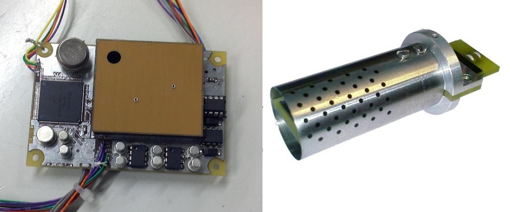
MicroARES is an electric field sensor comprised of an antenna protruding up from the lander structure and a power and data processing board inside the Warm Compartment of the EDM. The 27-centimeter ball antenna adjusts itself to the local atmospheric potential which can be measured against the grounded spacecraft potential. The instrument is designed to measure vertical and field potential at a frequency of 2kHz and potentials of 10mV/m to 10kV/m.
Because of the limited power supply of the EDM lander, DREAMS can not operate continuously. It is programmed to gather data in 31 pre-defined sampling windows for a cumulative duration of six hours per sol, consuming 200 Watt-hours of power during instrument operations over four sols.
Operation windows are between 5 and 60 minutes in duration with three longer windows of 40-60 minutes around sunrise, sunset and in the afternoon to study dynamics caused by rapid temperature changes while the afternoon slot maximizes the possibility of recording dust-raising events.
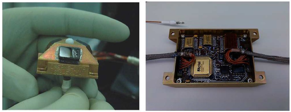
INRRI
INRRI – the Instrument for Landing-Roving Laser Retroreflector Investigations is an engineering demonstration of a laser retroreflector to be deployed to the Martian surface for testing. It is the first passive laser reflector on the surface of Mars and the first to be flown beyond the orbit of the Moon.
The INRRI Corner-Cube Retroreflector weighs under 25 grams, is 5.5 by 2.0 centimeters in size and is envisioned to be tracked by Mars orbiters capable of laser ranging or laser altimetry, or even laser communications. Its presence on Mars may also benefit future Martian geodesy or general relativity studies. INRRI has an aluminum body with eight fused silica Corner-Cube Reflectors within it, attached by a silicone rubber.
Installing a retroreflector on a rover or lander will enable precise georeferencing during the surface exploration activity. Having precise georeferenced data is useful in tracking sites that may be of interest for future exploration or sample return. Establishing a catalog of georeferenced sites of particular interest is a priority for NASA and ESA in the agencies’ long-term goals for Mars exploration.
The INRRI reflector is wavelength-independent, providing an initial platform to explore ranging on Mars, and prove the principles of laser communications between a surface vehicle and an orbiter.
DECA – Descent Camera
The Schiaparelli lander is equipped with a high-resolution imaging system to collect several photos during descent. DECA is the flight spare for Herschel’s Visual Monitoring Camera and becomes active after the separation of the Heat Shield to collect images of EDM’s landing site at Meridiani Planum. These images will be used to assess dust suspended in the atmosphere and to generate a three-dimensional model of the landing site.
DECA is around 9 x 9 x 9 centimeters in size and weighs 600 grams. It uses an addressable CMOS array detector providing black and white images. The optics have a focal length of 6.65 mm and the camera’s field of view is 60 by 60 degrees.
DECA is programmed to acquire 15 images at 1.5-second intervals. Collected images are stored in the camera’s onboard memory until being relayed to the lander memory after landing to avoid electrostatic discharges affecting the instrument.
AMELIA
AMELIA stands for Atmospheric Mars Entry and Landing Investigation and Analysis. It uses data from the EDM Engineering Sensors and auxiliary information to derive atmospheric density, temperature, pressure and wind parameters. Data is gathered by the accelerometers, gyroscopes, radar altimeter, UHF radio link, heat shield sensors and parachute performance sensors. Other data used by AMELIA includes the position of the lander within its landing ellipse, aerodynamic parameters and other models.
The AMELIA engineering study will piece together a complete reconstruction of EDM’s re-entry trajectory and atmospheric conditions to improve models of Martian atmospheric properties needed for future landing attempts.
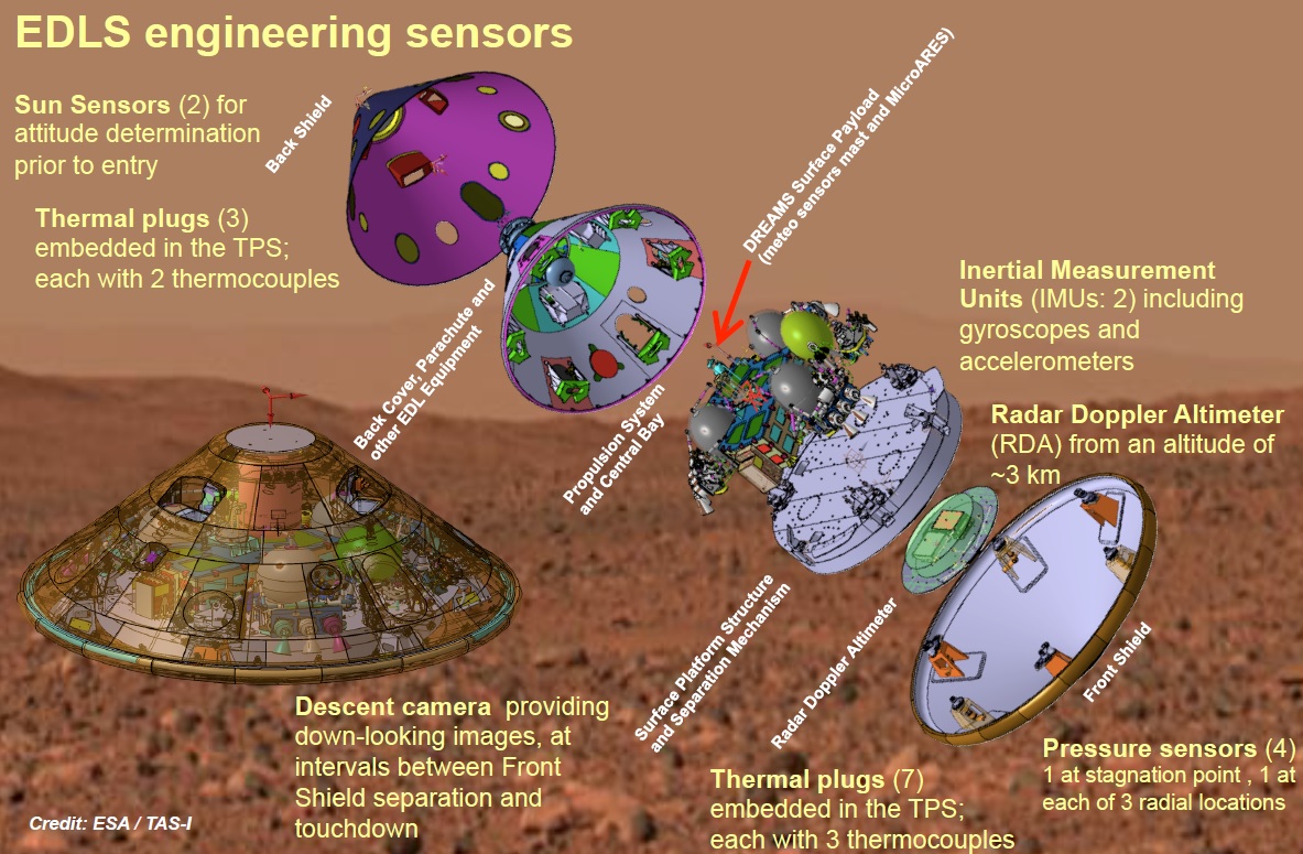
The EDL sensors employed by AMELIA are two sun sensors used for the acquisition of an attitude frame before re-entry, three thermoplugs in the back shield thermal protection system, a pair of inertial measurement units with gyros and accelerometers, the descent camera, seven thermal plugs in the forward thermal protection system, four pressure sensors in the heat shield, and the Radar Doppler Altimeter.
The goal is to combine data gathered during EDL to retrieve vertical profiles of atmospheric pressure, density and temperature starting from 160 Kilometers to the ground. It will also be attempted to retrieve wind profiles and assess the effect of dust suspended in the atmosphere on the performance of the Entry, Descent and Landing System. To date, only six vertical profiles of the Martian Atmosphere have been derived from in-situ measurements and Schiaparelli is the first to deliver such a data set during dust storm season.
COMARS+
COMARS is the Combined Aerothermal and Radiometer Sensors Instrument Package – aiming to measure aerothermal parameters on the exterior of the lander’s Back Shell during re-entry and atmospheric flight. Data gathered on the environment on the outside of the vehicle is essential in understanding the engineering and physics of entry into the Martian atmosphere.
When entering the Martian atmosphere, the back shell of the EDM lander experiences significantly lower convective heating than the front heat shield but on the backside, an instationary behavior develops which is hard to simulate, leading to large uncertainties in models. Additionally, radiative heating occurs on the back shell through the hot and excited carbon dioxide molecules flowing over the capsule shoulder region behind the bow shock.
In some areas of the back shell, radiative heat flux is expected to be significantly higher than convective heating, however, modeling the radiative heat flux over the back shell surface is even more difficult than simulating convective flow. Therefore, COMARS+ has been placed on this demonstration mission, setting out to gather hard data on aerothermal and radiative loads in different areas of the back shell.
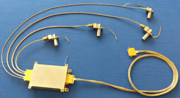
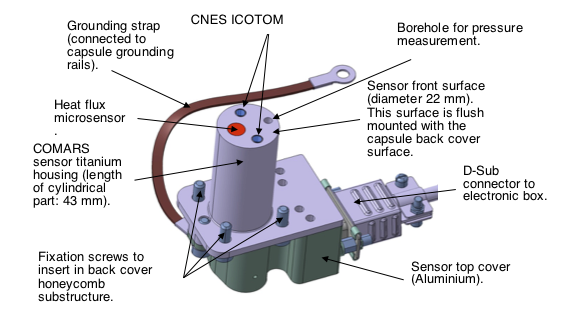
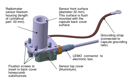
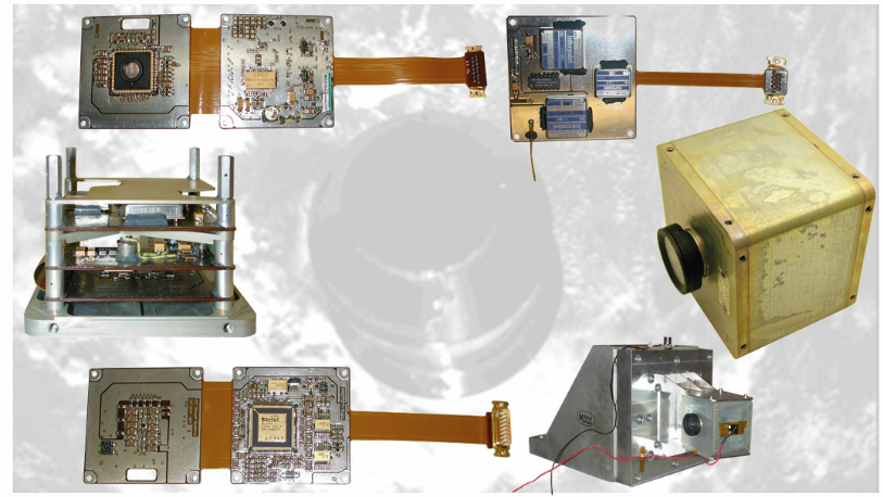
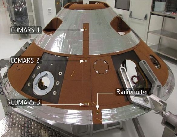
COMARS consists of three combined sensors spaced equally along a line across the Back Shell, and one broadband radiometer located close to the Back Shell – Heat Shield Interface. Inside the module is an electronics box delivering power to the sensors and collecting and recording sensor data. The entire COMARS+ payload has a mass of 1.73 Kilograms and requires 4.5 Watts of electrical power during operation.
Each of the COMARS sensors measures the static pressure, the temperature of the Back Shell skin, total heat flux (the rate at which energy is transferred to the Back Shell surface), and the radiative heat flux, the amount of heat transferred from the hot gas to the Back Shell through radiative processes. Each sensor plug is 22 millimeters in diameter and 43 millimeters long, mounted flush with the TPS surface.
The pressure measurement employs small Pirani-type pressure sensors and the total heat flux is measured by a commercial heat flux microsensor that also delivers a temperature signal. The radiative heat flux at two different spectral bands is measured by two sensors called ICOTOM, which are narrowband radiometers provided by CNES and installed on the upper two COMARS sensors. A broadband radiometer supplied by DLR is installed close to the COMARS 3 sensor and measures the infrared radiation in a broadband spectral range.
The electronics box is in charge of amplifying and multiplexing the 23 sensor and 8 telemetry signals to three analog acquisition channels.