
CYGNSS Spacecraft Platform
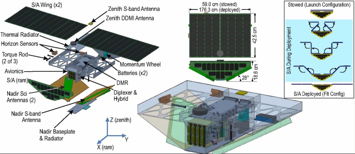
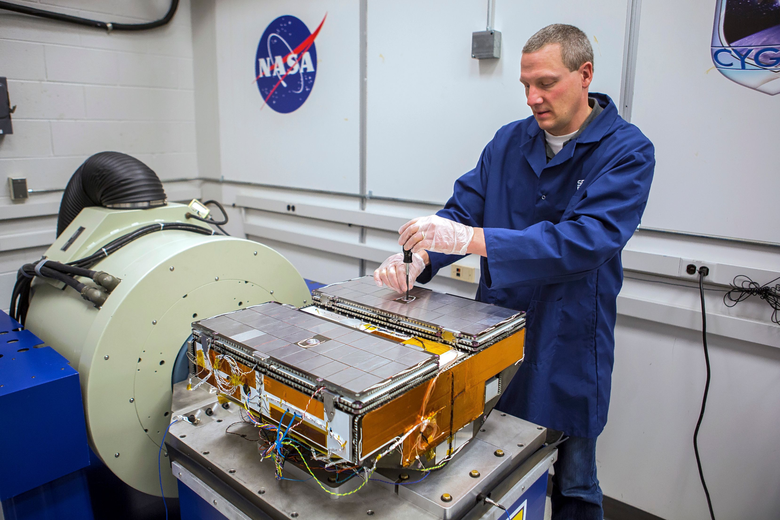
The eight CYGNSS ocean-wind measuring satellites employ a dedicated Microsatellite platform developed at the Southwest Research Institute to match the requirements for the mission. Each of the three-axis stabilized satellites has a launch mass of 28.9 Kilograms and, once in its deployed configuration, measures 52.1 by 163.5 by 22.9 centimeters in size.
Typical for microsatellites, CYGNSS features a single-string hardware architecture with functional and selective redundancy in critical areas to satisfy the minimum mission requirement of two years. The satellite platform has been designed from the onset for ease of manufacture, integration and testing to provide a low-risk and cost-effective solution across the satellite constellation.
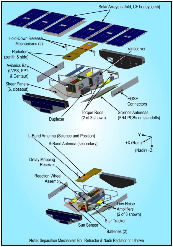
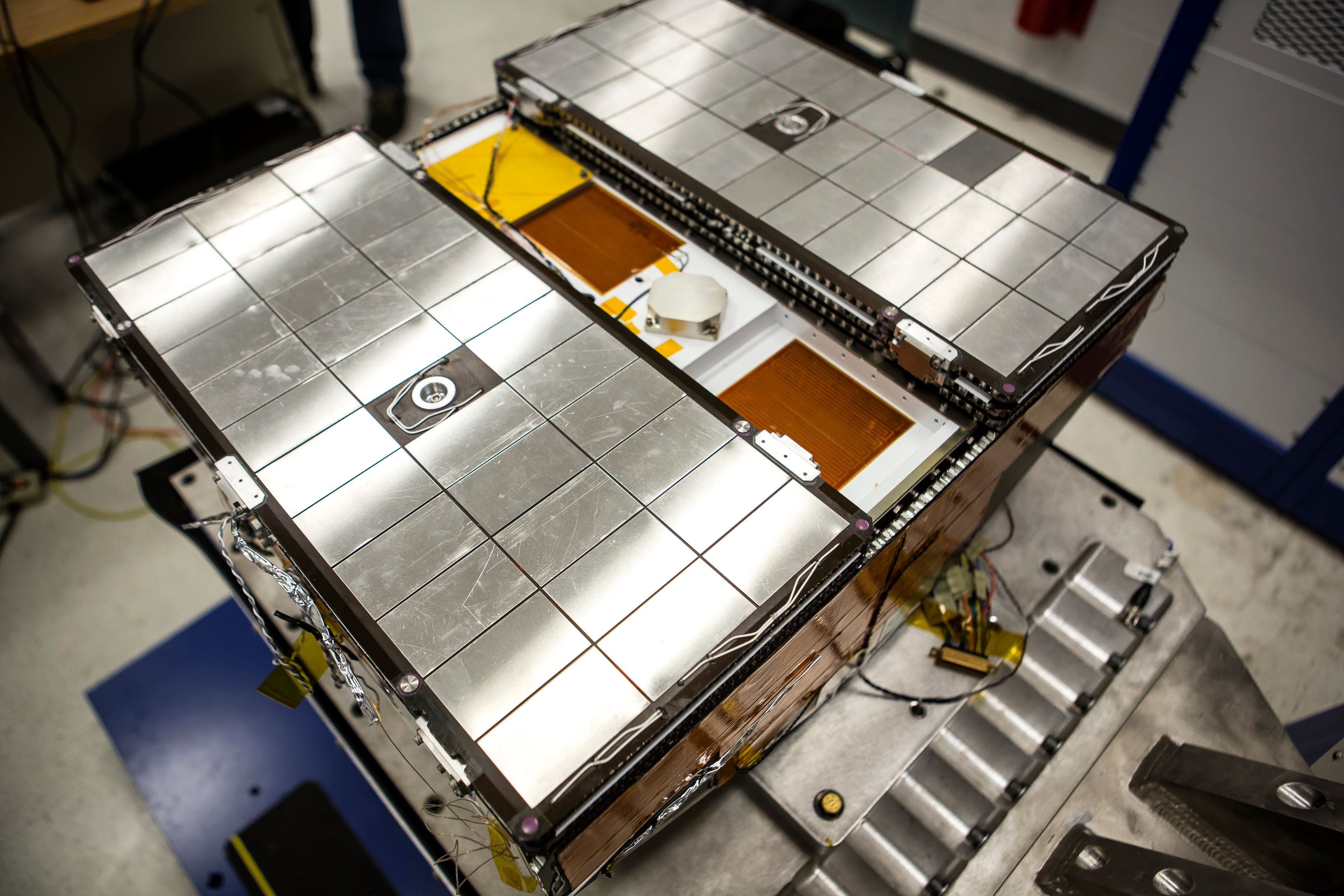
The CYGNSS satellite structure has been optimized to provide clear zenith (space-facing) and nadir (Earth-facing) viewing sectors for the GPS antennas while also choosing a spacecraft form factor that allows four satellites to be launched mounted side-by-side on a cylindrical payload adapter. The pyramidal spacecraft structure makes use of milled Aluminum components bolted together to establish an integrated and mass-efficient platform offering two bays for the platform systems and the instrument electronics.
The two bays form the core of the microsatellite, providing the mounting surfaces for all subsystem components including the solar panels and antenna assemblies.
The Electrical Power System of the CYGNSS satellite is built around eight solar panels – four are mounted to the satellite body and four are deployed to form a large array on the space-facing side of the spacecraft. This space-facing array comprises two body-mounted panels, each attached to a pair of deployable panels stowed in a Z-fold arrangement so that the solar cells of the outer panels are exposed to the sun while the arrays are still in their launch configuration. The remaining two solar panels are installed on the ram (forward) and wake (rear) of the spacecraft and enable supplementary power generation when the satellite is oriented less sun favorably.
This EPS design ensures the CYGNSS satellite can remain in standby mode for an indefinite period of time before the deployable arrays are folded out. Overall, the triple-junction solar cells cover an area of only 0.71 square meters with a margin of 30% during maximum eclipse periods.
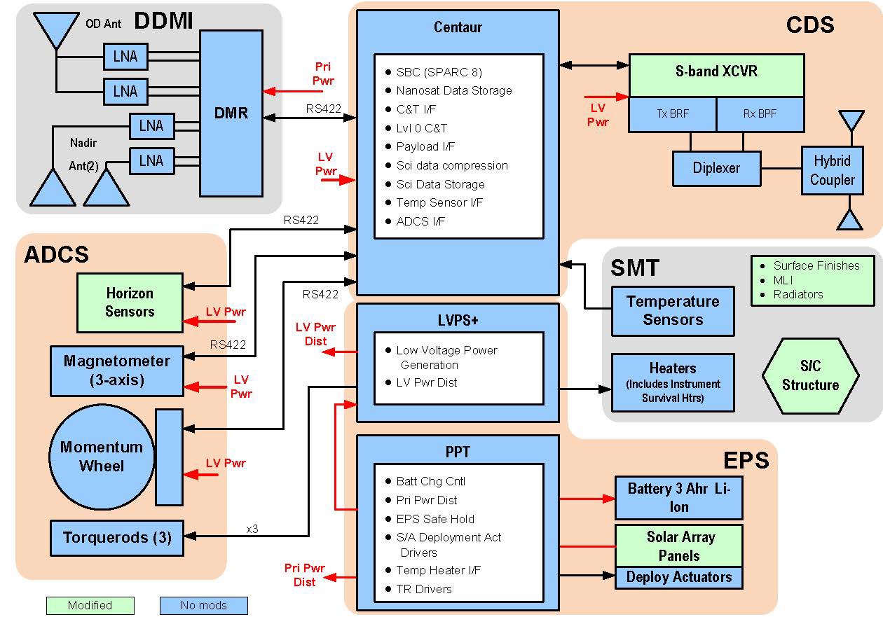
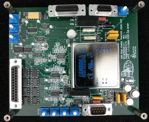
The arrays feed power to a 4.5 Amp-hour Li-Ion battery assembly regulated by a Peak Power Tracker and dedicated hardware is in charge of power distribution through a 28.8 (+/-4)-Volt power bus. The Peak Power Tracker is responsible for battery management, primary power distribution, commanding the power system into safe hold, driving the deployment actuators and providing the heater power interface. PPT is based on a 40-Watt DC-to-DC converter that accepts the solar array voltage of 36 to 72 V and converts it to the 28-Volt primary power bus.
A secondary power supply is is provided through a Low-Voltage Supply Unit which accepts the 28-Volt main bus and converts it to voltages of 12, 5 and 3.3 V for the various electronics on the satellite.
The power feed to the satellite payload is independently switched and over-current protected. During nominal mission operations, CYGNSS draws 38.3 Watts of electrical power while mean power generation at the end of the satellite’s expected life should be 59 Watts.
Thermal Control on the CYGNSS satellites is provided by a combination Multilayer Insulation and heaters to ensure critical components are maintained within their operational temperature envelope. The main radiator is installed on the zenith side of the satellite with a second radiator mounted on the nadir baseplate to dissipate heat from the internal electronics directly coupled to the radiators.
CYGNSS employs a momentum-biased three-axis stabilization system with attitude sensing completed by a Star Tracker, horizon sensors and three-axis magnetometer; and actuation delivered by a reaction wheel triad and magnetic torque rods.
The Star Tracker collects images of the star-filled sky that are then compared to a catalog of bright stars for the calculation of the precise three-axis orientation in space with an accuracy of 6 arcsec. Sun and Earth sensors are secondary attitude determination sensors in use during spacecraft de-tumble and safe modes. The magnetometer has a 10-nano-Tesla sensitivity along a dynamic range of +/-50,000nT to measure the Earth’s magnetic field vector and strength in order to deliver data for commanding of the torque rods.
Reaction Wheels function by accelerating a rotating inertial mass to introduce a torque acting on the spacecraft in the opposite direction. Control along all three axes is possible with three wheels. To avoid spinning the wheels at excessive rates, they are regularly spun down which also creates a torque that has to be countered by the magnetic torquers which create angular momentum by running a current through coils in the presence of Earth’s magnetic field.
The CYGNSS Reaction Wheels can deliver a torque of 0.6mNm with an angular momentum of 18mNms.
Three primary attitude determination and control modes are available for CYGNSS – rate damping after separation from the launch vehicle and anomaly recovery, nadir acquisition to transition to an Earth-pointed orientation, and normal pointing mode.
Rate damping uses a B-dot algorithm to command the torque rods opposed to the rate of change on the magnetic field vector (corresponding to the spacecraft’s rotation) to fully reduce body rates so that the other attitude sensors can begin taking data.
Once body rates are nulled out, CYGNSS transitions into nadir acquisition where the Earth horizon sensors are used to determine a rough Earth vector and orient the satellite accordingly. The two Earth-sensors installed on the spacecraft include two thermopile detectors which can view the Earth limb and measure the dip angle with respect to the horizon, yielding pitch and roll measurements relative to Earth.
Normal pointing will see the satellite’s zenith deck pointed to space and the nadir-mounted antennas facing the Earth with the satellite slowly rotating around its pitch axis to keep pointing at Earth. On-orbit positioning data is provided via GPS through the satellite’s instrument payload.
Overall CYGNSS achieves a pointing accuracy of 2.8 degrees which is sufficiently accurate to carry out the scientific mission.
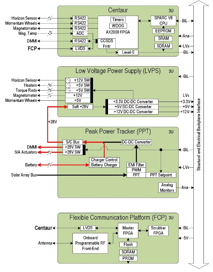
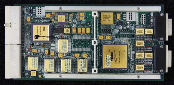
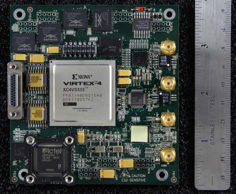
The brain of the CYGNSS satellite is a circuit board known as Centaur, hosting all command and control functions needed to operate the satellite and its instrument payload. Centaur is built around a LEON3 Single-Board Computer that acts as the spacecraft controller, featuring a dual-core processor with a 4x4kB i- and d-cache and interfaces to MRAM, SDRAM and Flash memory units that are used to hold the flight software and for data storage. Internal communications across the CYGNSS spacecraft are facilitated by analog RS-422 interfaces, and LVDS/SpaceWire.
Centaur communicates with all spacecraft systems using a Field Programmable Gate Array which also incorporates timers for time synchronization and a watchdog that protects the spacecraft against lock-ups by rebooting the computer in case the watchdog timer is not re-set at regular intervals. Centaur, the Peak Power Tracker, the Low Voltage Power Supply and the Flexible Communication Platform all reside on a structural backplane assembly that provides electrical and data connectivity.
The Flexible Communication Platform receives data from Centaur via LVDS and is in charge of formatting data for storage and downlink, hosting the spacecraft primary Flash, SDRAM and PROM memory units. A 4GB Flash memory unit is used for storing satellite housekeeping and instrument data, providing sufficient space for over ten days of continuous science operations without downlink.
CYGNSS makes use of software defined radio to create a communications system that can be optimized over the course of the flight. The communication platform delivers QPSK-encoded data at up to 5Mbps for downlink in the 2GHz S-Band, typically operated at 4Mbit/s. The FSK uplink receiver is capable of accepting data at 64kbit/s. CYGNSS employs an S-Band Microstrip Patch Antenna system comprised of a pair of antennas – one on the nadir side and one mounted on the zenith panel to enable communications in all satellite attitudes.
Deployment Module
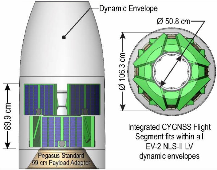
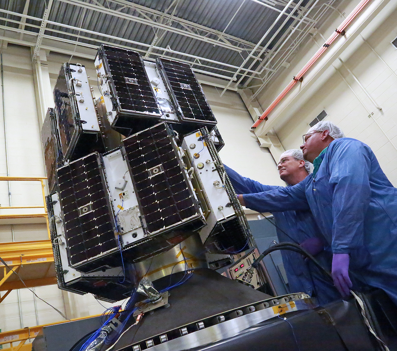

The CYGNSS Deployment Module was developed by Sierra Nevada Corporation and acts as the constellation carrier during launch before deploying the satellites into the proper orbital configuration. The Deployment Module (DM) consists of two aluminum tiers, each 50.8 centimeters in diameter with four mounting/separation mechanisms to host four satellites, separated by 90 degrees to provide sufficient volume for the satellites and enable separation into different directions.
Tier 1 is clocked 45 degrees from the second tier to provide appropriate orbital dispersal vectoring for the satellites to rule out any contact after release from the launch vehicle.
Separation of the observatories is accomplished with high-reliability Frangibolts and four push springs that send the satellite’s off at precisely planned velocities and minimal tip-off errors. The spring load is set by torquing the Frangibolt actuator in the satellite’s nadir baseplate and compressing the springs.
The DM facilitates its own avionics system hosting an electronic sequencer that is in charge of commanding the release of the observatories in pre-determined intervals programmed into the sequencer memory. This sequence is initiated by command from the launch vehicle when it arrives in the required orbit. For safety, the deployment system makes use of a two-stage command, single-fault tolerant actuator driver with a pre-flight Safe/Arm function to fully disarm the system until needed for launch.
The DM hosts a 140 Watt-hour Li-Ion battery delivering 28 Volts of power to the avionics and deployment Frangibolt actuators. DM avionics also provide data and power links for spacecraft command and telemetry connectivity to reach individual satellite.