CYGNSS Instrument Overview
The primary instrument of NASA’s Cyclone Global Navigation Satellite Mission (CYGNSS) is the Delay Doppler Mapping Instrument (DDMI) that is installed on all eight constellation satellites to measure winds over the ocean via analyzing scattered signals from the Global Positioning System (GPS) satellite constellation.
GPS operates a constellation of approximately 30 active satellites in six orbital planes, 20,000 Kilometers in altitude, transmitting different L-Band signals used for navigation and precise timing applications as well as a wide variety of other applications including meteorology. At least four satellites are simultaneously visible from any position on Earth.
GNSS occultation measurements for atmospheric measurements is a proven method for the acquisition of temperature, pressure and humidity profiles from high altitude to near-ground level. The science and methodology behind GNSS occultation measurements is well established and has been employed for many scientific projects as well as operational meteorology systems.
Reflectometry of GNSS signals (using Earth-reflected GNSS signals to obtain information on land & ocean properties) has been proposed in the late 1980s for ocean sensing and in 1993 for ocean altimetry with first tests carried out in the early 2000s.
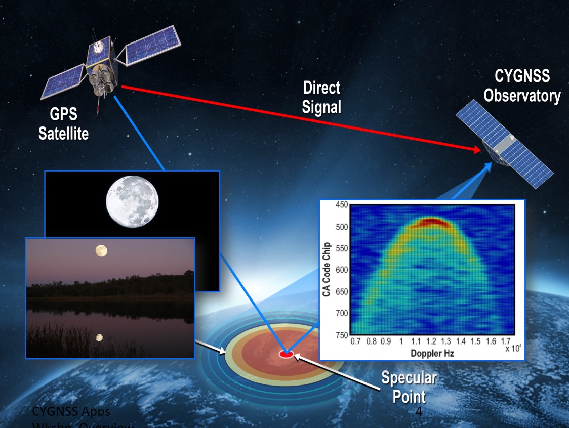
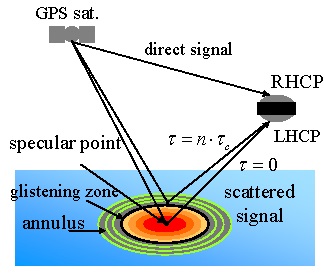
The DDMI instrument is designed to receive direct signals transmitted through space from the GPS satellites and scattered reflections of the same signal bouncing off the Earth’s oceans, altering the signal properties from which ocean roughness and local wind speed can be extracted.
The DDMI instrument for the CYGNSS constellation is provided by the U.S. branch of Surrey Satellite Technology Ltd. (SSTL) based on space-proven hardware with flight heritage dating back over a decade.

The first SSTL spaceborne GPS reflectometry instrument was flown on the UK-DMC-1 satellite launched in September 2006 and demonstrated that the miniature GPS receiver array was capable of recording the weak scattered GPS signals.
SRG-10, as the instrument was known, comprised RHCP (Right-Hand Circular Polarization) receive antennas on the zenith side of the spacecraft and LHCP (Left-Hand Circular Polarization) antenna on the nadir side. The RHCP antennas recorded the direct GPS signals as a coherent reference for the coded GPS transmit signals while the forward-scattered signal was collected by the LHCP antennas.
UK-DMC-1 showed that GPS reflectometry was a suitable technique to resolve the spatial distribution of ocean surface roughness. After this proof-of-concept, scientists began actively working on wind-speed retrieval algorithms from the Delay Doppler Maps generated by the instrument, leading into the development of SRG-ReSI – the Space GNSS Receiver – Remote Sensing Instrument.
SRG-ReSI was developed by SSTL in cooperation with the National Oceanographic Centre, UK, the University of Bath, and Polar Imaging Ltd. The compact instrument has been improved to be able to complete data processing functions in space, converting raw signal measurements directly into Doppler Delay Maps. Also, the instrument can be reconfigured to track different navigation signals coming from new constellations (Compass/Beidou & Galileo) or apply spectral analysis to received signals.
In essence, SRG-ReSI combines functions that had required three separate units on earlier missions: receiving up to four dual-frequency signals, processing data in real time, and storing data products for later downlink to the ground.
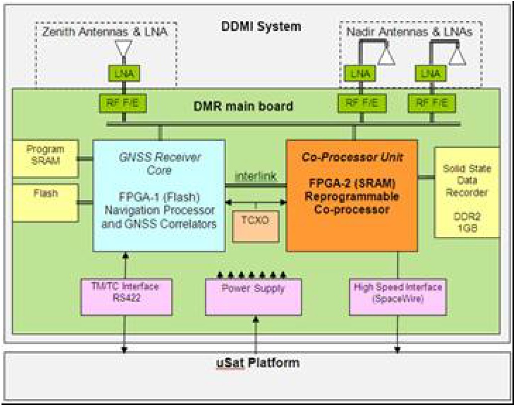
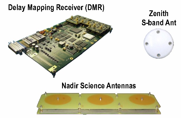
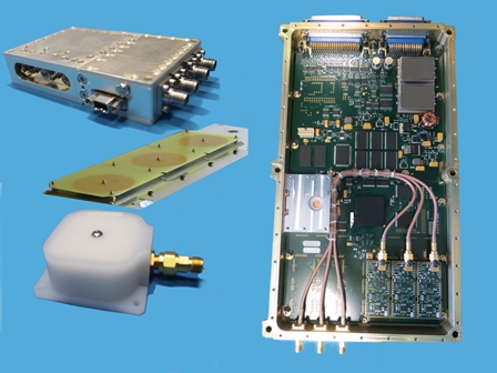
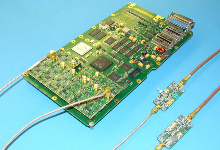
DDMI consists of the SRG-ReSI Delay Mapping Receiver, a pair of Nadir Antenna Assemblies and a Zenith Antenna Assembly. The Delay Mapping Receiver consists of Low-Noise Amplifiers and eight RF front-ends divided in two groups – one optimized for operation in the L1 navigation frequency (Max2769) while the other (Max2112) can be re-programmed to any GNSS band – SGR-ReSI uses GPS&Galileo L1 and L2C or L5 GPS bands. The front ends interface with their associated processor boards with Field Programmable Gate Arrays (one flash-based, the other SRAM-based) with interlink to allow the exchange of data for storage of data from multiple front-ends. Data is stored in a 1Gbyte DDR2 solid state data recorder that interfaces with the reprogrammable co-processor and the SpaceWire data bus of the spacecraft.
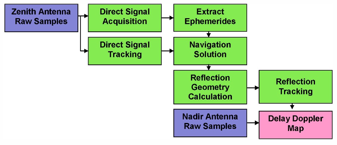
The Flash FPGA, also known as the GNSS Receiver Core, interfaces with the zenith antennas & associated front ends for direct collection of L1 signals. These signals are then processed to extract the GPS ephemerides to gain knowledge of the GPS satellite position as well as the current position of the CYGNSS observatory.
The GPS satellite position and the location of the CYGNSS satellite are then fed into a calculation of the reflection geometry which yields the position of the reflected signal (=specular point), the estimated delay and the estimated Doppler of the reflection as seen from the CYGNSS satellite.
The nadir-pointed patch antennas interface via RF Front ends optimized for the L1/L2 Bands with the SRAM FPGA known as the Reflectometry Processing Unit. Raw samples of the GPS scatter signals are processed with the known reflection geometry to yield Delay Doppler Maps. Data sampled from the nadir antennas is put through a multiplication process and a Fast Fourier Transform Matrix to fill out the Delay Doppler Map on a row-by-row basis followed by accumulation of each point over several hundred milliseconds to differentiate the weak signals from the noise.
Two nadir-patch antenna assemblies are used to track two scatter signals each in order to achieve a broad swath to cover a large area of the ocean. Typically, there are many specular reflections from the surface at any given time due to the large number of GPS satellites, however, onboard resources only permit four Delay Doppler Maps to be generated per second. Selection of the reflection to be measured is based on the location within the highest sensitivity region of the nadir antenna pattern.
Given the measurement technique, wind speeds are derived over a 25 by 25-Kilometer region centered on the specular point. In total, the CYGNSS constellation delivers 32 simultaneous measurements per second from all over the globe. Each satellite assembles a 25-Kilometer swath that continues howeverlong the satellite moves over water.
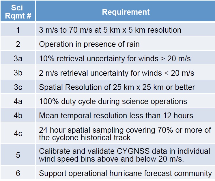
Per the mission’s requirements, the SGR-ReSI instrument shall be able to measure winds with an error of less than 2 meters per second or 10% of the wind speed, whichever is greater. The measurement range extends from 3 to 70m/s and the spatial resolution after ground processing is 5 x 5 Kilometers.

The instrument can operate in two modes – either acquiring short bursts of raw data that is directly stored in the Solid State Data Recorder, or using the co-processor to generate Delay-Doppler Maps as data products that are directly send to the spacecraft memory via Space Wire. In the nominal operations mode, DDMI completes onboard processing into Delay Doppler Maps because they represent a much smaller volume of data compared to the raw data rate.
However, the mission will, at regular intervals, sample in raw mode so that researchers can fully analyze and re-analyze the acquired data using different processing schemes to a) ensure the onboard processing system is functioning properly and b) tweak the retrieval algorithm over the course of the mission to improve data quality.
The zenith-facing antennas can also be used for the standard GPS orbit determination as well as occultation measurements for atmospheric science, combining several instrument packages into one compact system. Overall, the system achieves a navigation accuracy of 5 meters in position, 10cm/s in velocity and 200 nanoseconds in timing.
Data Products
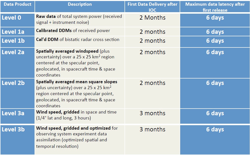
Data delivered from the CYGNSS spacecraft is known as Level 0 products, representing raw data of total system power comprised of the received signals plus instrument noise.
Delay Doppler Maps calibrated for receiver power are known as L1a products and additional calibration for bistatic radar cross section yields L1b data. The actual wind parameters are extracted as part of L2 processing, providing spatially averaged windspeeds and uncertainty values for 25 by 25-Kilometer areas based on geolocation and spacecraft time (2a) as well as products of mean square slopes over the same 25 x 25km area (2b). Finally, Level 3 products are wind speed products gridded in time and space (0.25° lat/lon; 3 hours).
The fully calibrated L2 data will be used for research and will be made available to the external science community. CYGNSS has the goal of measuring ocean surface winds in all weather condition with special focus on dynamics in developing tropical storms at a sufficient spatial and temporal resolution to reveal rapid intensification processes. While operational use by CYGNSS data is not foreseen in the core objectives of the mission, it will be attempted to minimize data turnaround time to deliver wind measurements to the weather forecasting community as soon as possible after acquisition.