
Sentinel-5P Satellite Overview
Sentinel-5P, formally the Sentinel-5 Precursor – Atmospheric Monitoring Satellite, is a pre-operational mission flying within the framework of the European Copernicus Program, also known as the Global Monitoring for Environment and Security (GMES) program, representing a large collaborative effort to obtain a comprehensive set of Earth observation parameters via a series of sensors deployed into different orbits and distributing data free of charge for a wide variety of worldwide applications.
Sentinel-5P has the specific goal of filling a gap between atmospheric monitoring systems on ESA’s Envisat (failed in 2012) / NASA’s Aura mission (launched in 2004) and the upcoming operational Sentinel-5 mission that will launch around 2020 as a hosted payload on the MetOp Second Generation Satellites.

Under Copernicus, the Sentinel-1, 2 and 3 missions are designed as stand-alone satellite missions, collecting various parameters on Earth’s land surface and ocean states via high-resolution, multi-spectral imagers (S2), Synthetic Aperture Radars (S1) and specialized sensors like radiometers, altimeters, hyperspectral imagers (S3) while the Sentinel-4 and 5 missions are designed as hosted payloads destined for Geostationary and Low Earth Orbit to collect atmospheric parameters, thus giving Copernicus a full picture of Earth’s land surface, ocean parameters and atmospheric dynamics. Sentinel-4 and 5 are flying under the GMES Atmosphere Service, serving operational purposes like weather forecasting as well as various areas of research into climate and other phenomena.
>>Sentinel Program & Satellites
The need for an atmospheric gapfiller mission was identified at the ESA ministerial conference in 2008 and the mission’s scope was defined under the GMES Space Component Program.
ESA awarded a contract to Astrium Ltd. (now Airbus Defence and Space) in December 2008 to act as prime contractor for the Sentinel-5P mission – providing the satellite platform, integrating the ESA-provided instrument payload and completing all pre-launch testing and integration tasks for the mission.
Sentinel-5P is a single-instrument satellite hosting TROPOMI – the Tropospheric Monitoring Instrument – as its sole payload, a pushbroom instrument with four hyperspectral channels stretching from the Ultraviolet wavelength range into the short-wave infrared spectrum to detect atmospheric constituents, clouds and aerosols. Data delivered by Sentinel-5P will be fed into the Copernicus Atmosphere Monitoring Service to transform raw data into valuable information like air pollution forecasts that can be used by decision-makers to take action under environmental policies. The mission also serves as science data continuity mission to keep up long-standing atmospheric records needed in the study of climate phenomena that stretch over long time scales.
Satellite Platform

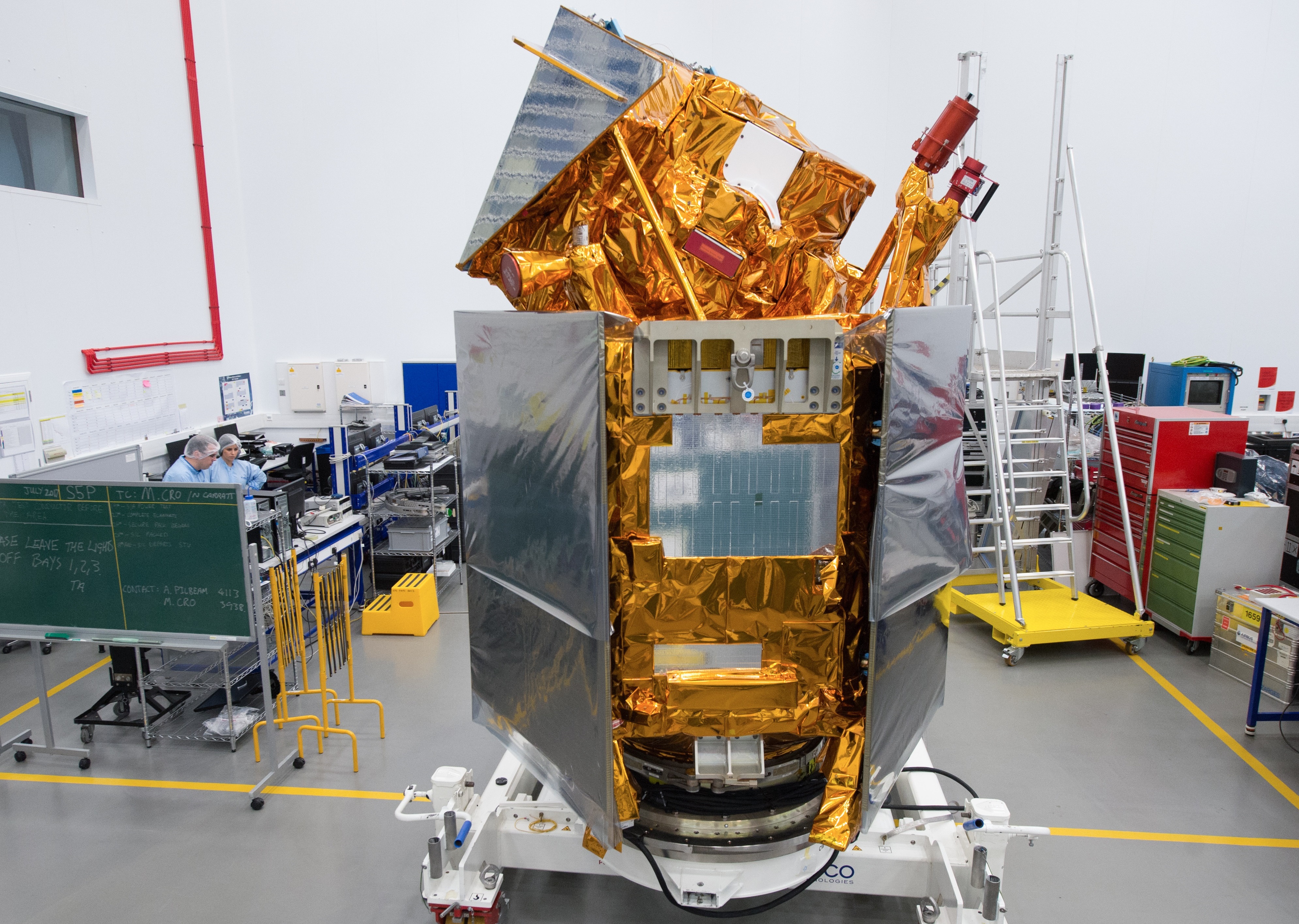
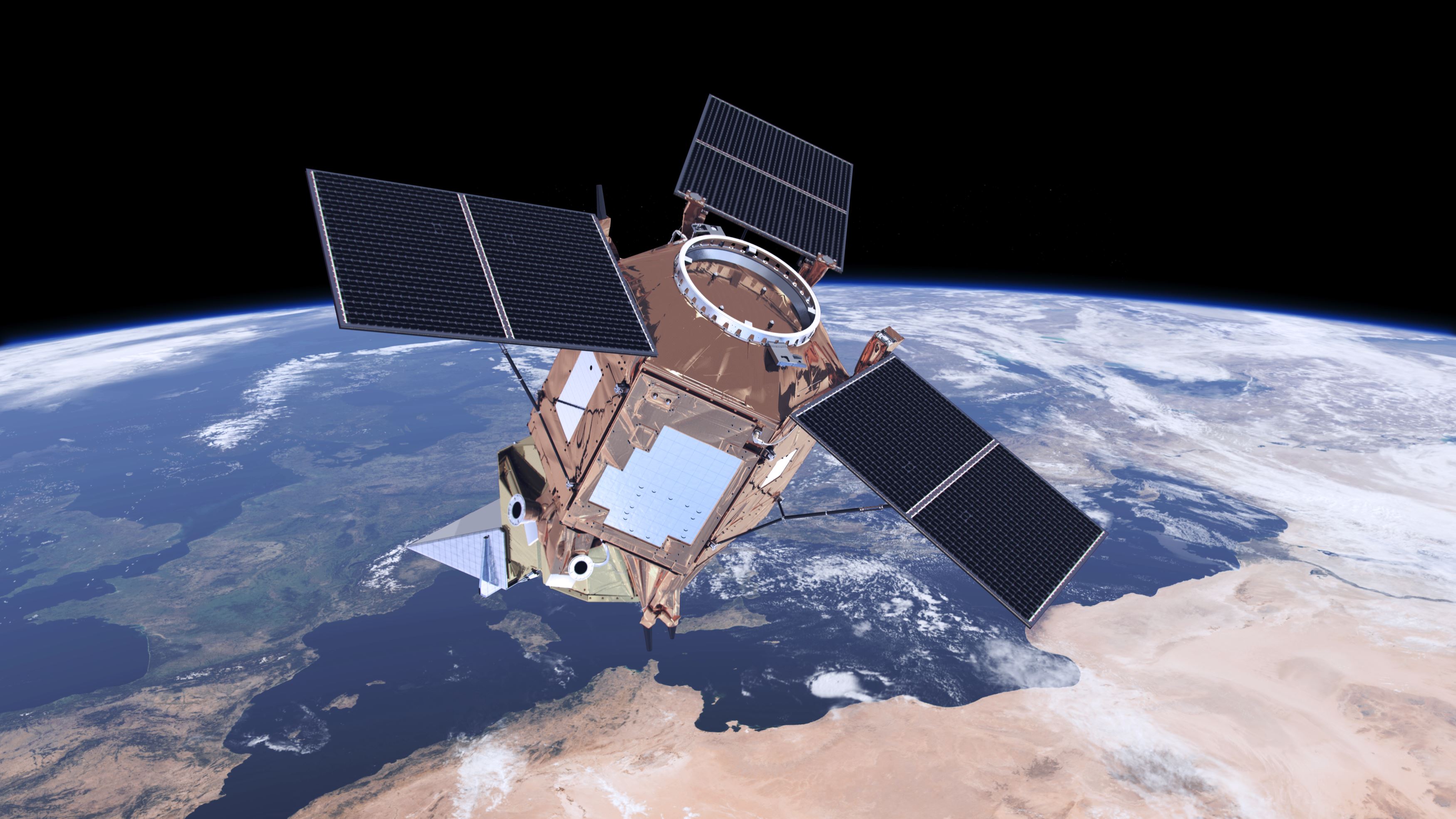
The 820-Kilogram, 5.6-meter tall Sentinel-5P satellite is based on the AstroBus-L 250M satellite platform, a member of a family of Airbus Defence and Space satellite platforms covering a Low Earth Orbit mission range from 125 to 4,000 Kilograms. The AstroBus satellites are built to share a number of common avionics components to streamline the production line and reduce overall cost. As such, Sentinel-5P draws heritage from the Spanish SeoSat/Ingenio project and the Spot-6 and 7 satellites as well as two additional Earth observation projects developed in parallel to the S5P spacecraft.
The AstroBus-250 platform uses a modular approach and provides a one-fault tolerant architecture across all subsystems – deemed sufficient for a gapfiller mission such as Sentinel-5P with a reliability of 0.75 over the satellite’s planned 7-year service life. On-orbit performance of previous AstroBus-250 satellites and smaller members of the family has shown the robustness and efficiency of the bus.

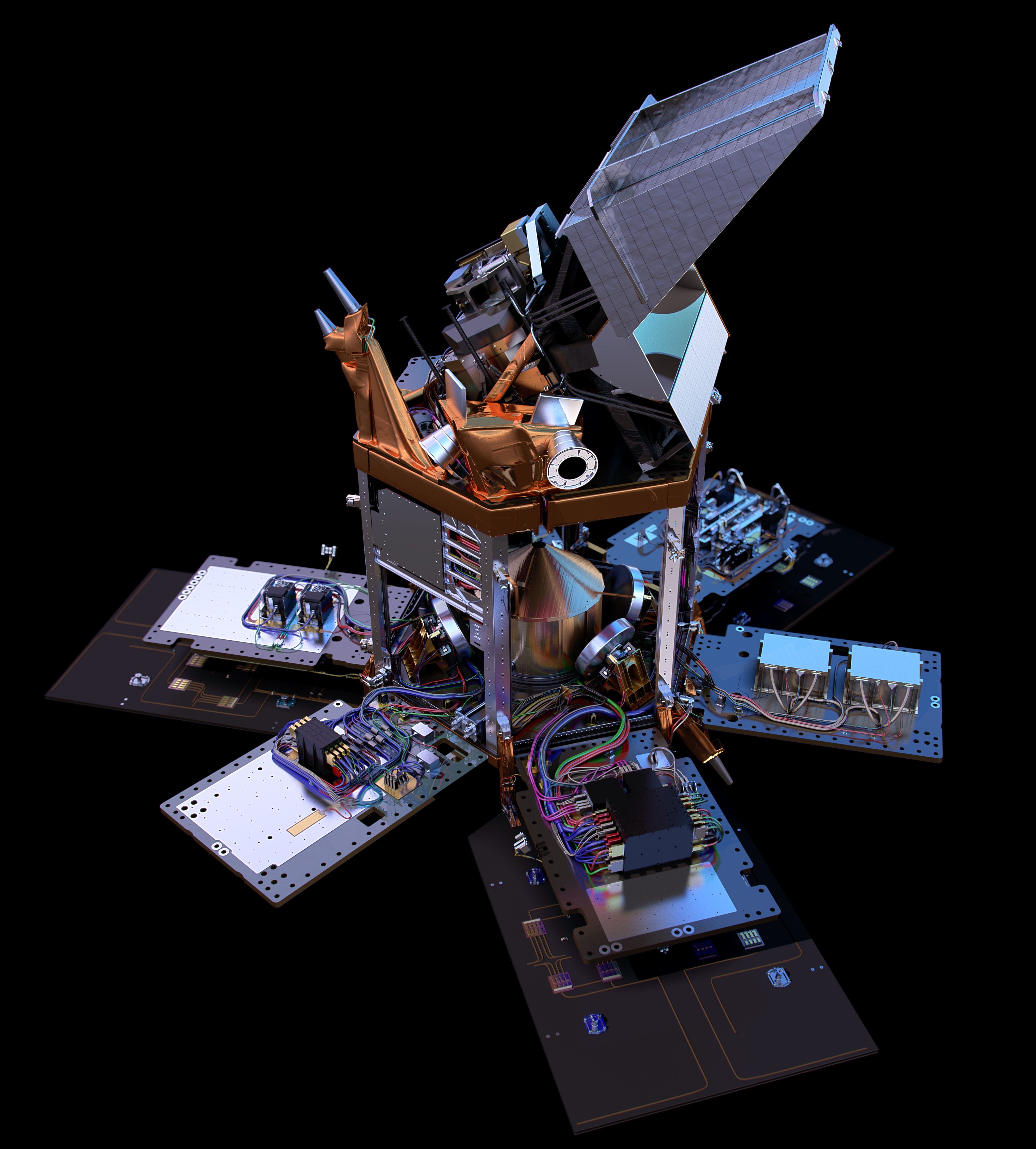
The Sentinel-5P satellite platform utilizes a hexagonal structure with the standard launch vehicle interface ring hosted in the aft section of the bus and the TROPOMI instrument sitting on the forward side of the spacecraft. All six side panels of the satellite structure serve as mounting platforms for the subsystem components and can be opened up to allow for easy access to the satellite’s various electronics boxes and other components. All bus subsystems are facilitated on the interior of the side panels as well as the TROPOMI Instrument Control Unit; the sole exception being the propulsion system which resides on the bottom panel of the satellite.
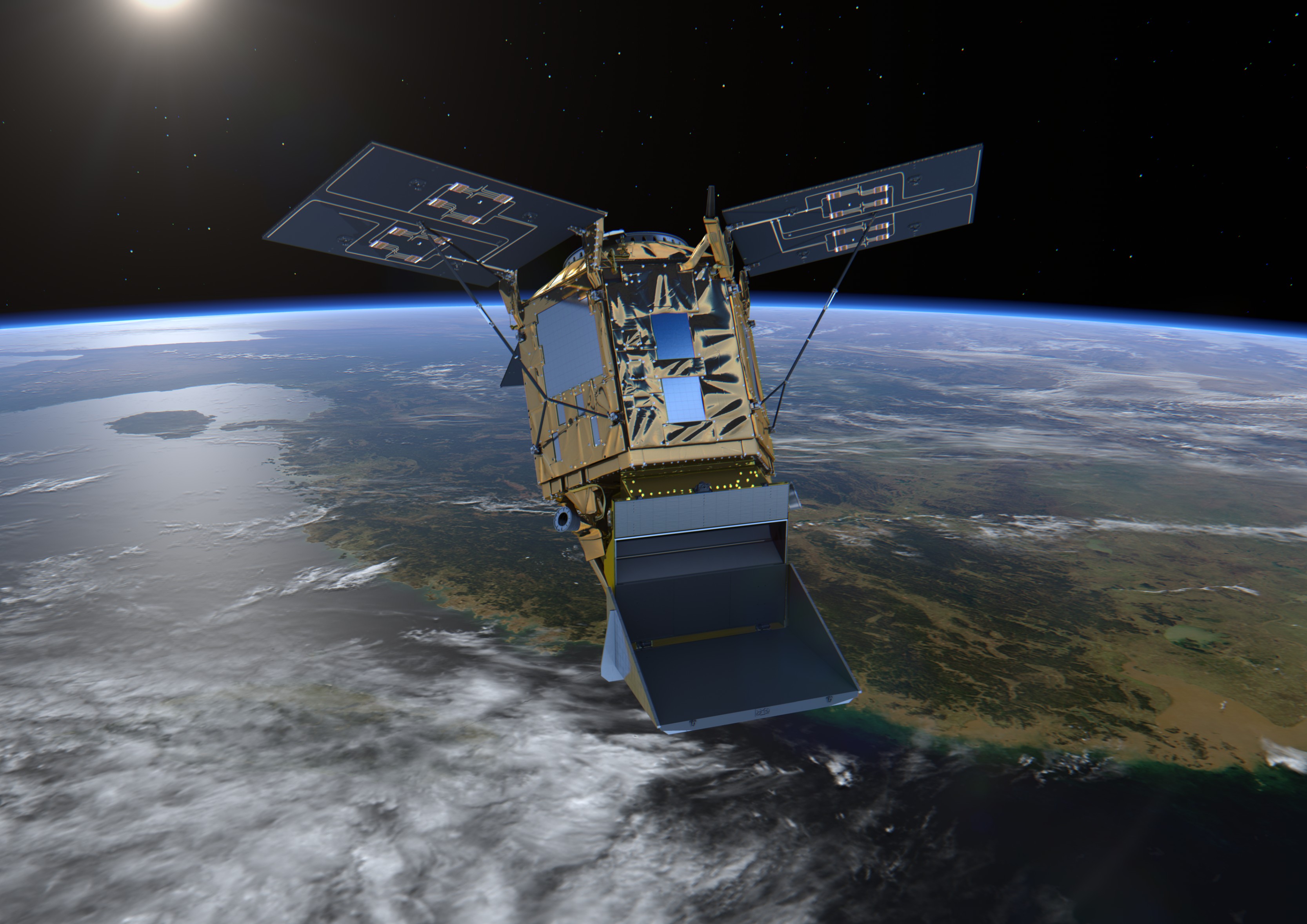
The Electrical Power System of the Sentinel-5P satellite comprises three fixed, 1.75 by 1.24-meter solar arrays with Gallium-Arsenide cells, stowed against three of the side panels for launch and deployed in-plane with the launch adapter on the zenith-facing side when the satellite is in its duty attitude. The arrays are sized according to the satellite’s power needs with a combined area of 6.3 m², generating 1,500 Watts of power at end of life. A central component within the power system is the PCDU (Power Conditioning and Distribution Unit) – tasked with switching and protecting of the power buses using a combination of Latch-up current limiters and Fault Current Limiters that allow critical satellite systems to remain powered in case of an anomaly.
The PCDU is also responsible for regulating the charge of a 156 Amp-hour, 104-string battery assembly and distributing primary and secondary power to all satellite subsystems. For robustness, the PCDU functions are realized without the use of software. The average power consumption across the satellite is expected to be 430 Watts.
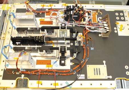
Sentinel-5P hosts a commercial-off-the-shelf PM-22 monopropellant propulsion system employed by a number of Airbus Defence and Space Missions, capable of assisting in satellite attitude control but mainly used for orbital fine-tuning at the start of the mission, orbital maintenance as the mission progresses and avoidance maneuvers in case the satellite comes close to another orbiting object. The propulsion module hosts a central tank holding 82 Kilograms of Hydrazine, fed via pressure regulators, filters and isolation valves to four 1-Newton thrusters configured in two redundant pairs. The thrusters make use of the decomposition of Hydrazine over a metallic catalyst bed, creating gaseous reaction products used to generate a thrust component.
The 1N thrusters can tolerate supply pressures of 5.5 to 23 bars to generate a thrust of 0.36 to 1.45 Newtons. The corresponding specific impulses are 205 seconds at the lowest supply pressure and 221 seconds at the highest pressure. Each thruster assembly weighs about 0.23 Kilograms and can be operated in steady-state mode and pulse mode for attitude control.
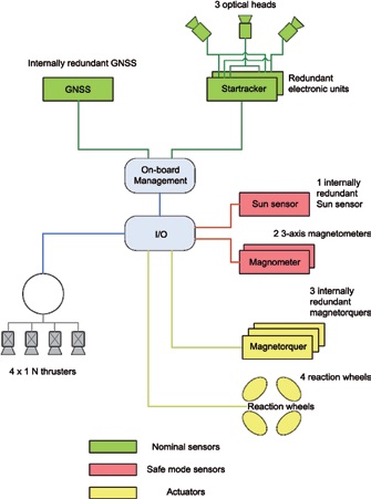
The Sentinel-5P Attitude Determination and Control System is the same as on the Airbus-built KazEoSat-1 which itself is identical to that of the Ingenio satellite with the addition of a third star tracker head. Attitude determination in nominal operations mode is provided by a Sodern Hydra Star Tracker with three optical heads and a redundant electronics assembly; a pair of three-axis magnetometers provide readings for the actuation of the magnetic torquers and two Coarse Sun Sensors are used for safe mode pointing to ensure proper power generation.
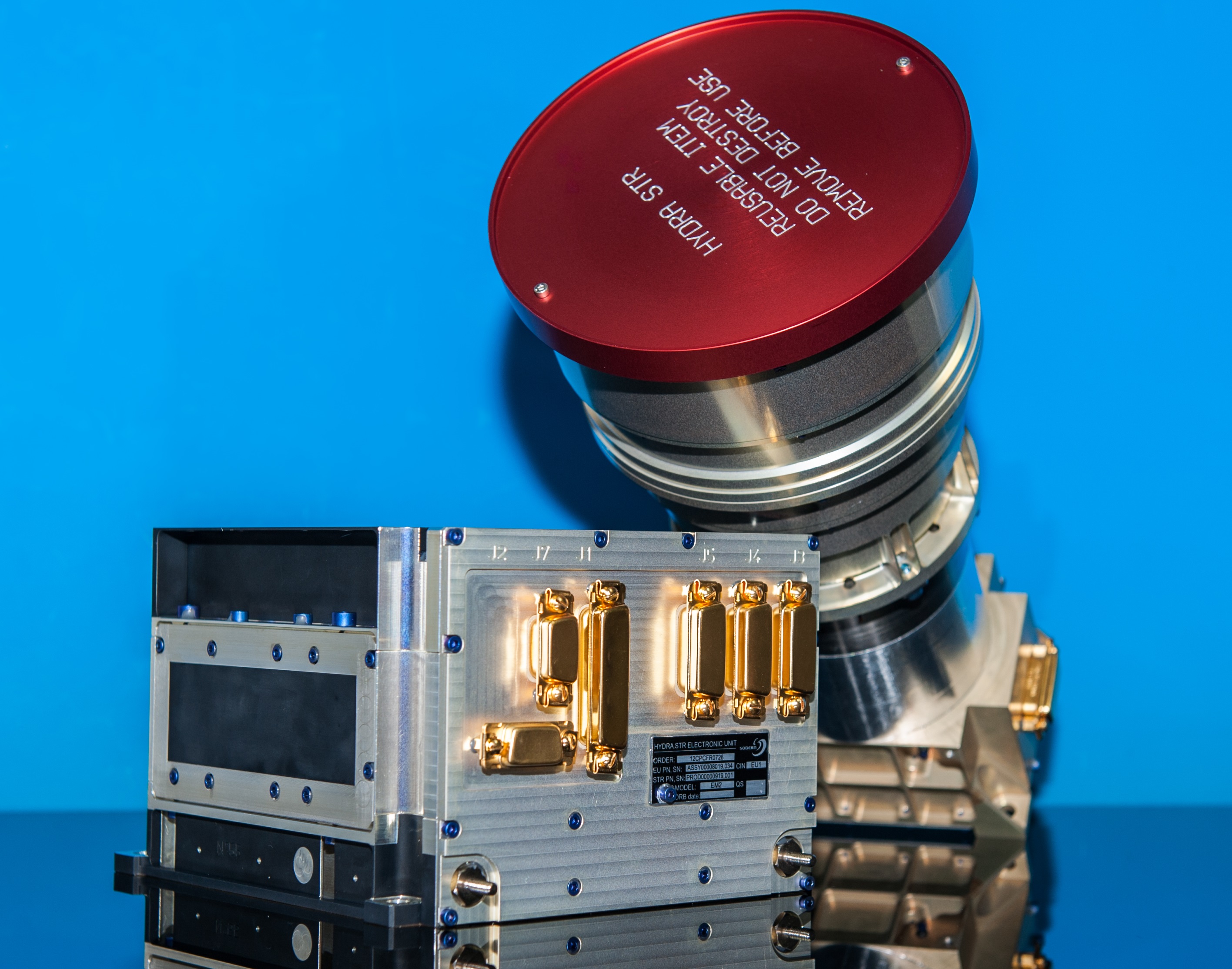
The Hydra Star Trackers can provide attitude tracking in two heads simultaneously, acquiring the satellite’s three-axis orientation within 2.5 seconds from a lost in space scenario at body rates up to 8 deg/s. A dual-frequency GPS terminal with redundant receivers can be used for orbit determination with an accuracy of 3 meters, providing information for time and geo-tagging of instrument data.
Attitude actuation is provided by four reaction wheels and three magnetic torquers are used for coarse control and for momentum dumps from the reaction wheels. The star tracker delivers pointing knowledge of up to 30 µrad while the attitude control system provides a pointing accuracy of 500 µrad. The attitude control system provides optional yaw pointing (off-nadir), though nominal data collection will be completed pointing directly to the nadir given the instrument’s wide field of view.
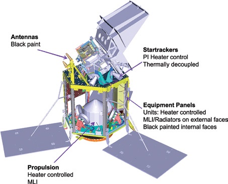
The satellite’s Thermal Control Subsystem relies on a combination of active and passive components in the form of heaters on the active side and coatings, blankets and radiators on the passive side. Radiators for heat rejection are located on the outside of the satellite side panels and the satellite platform and TROPOMI instrument are largely decoupled from a thermal standpoint, though the bus is equipped to take over for survival cases and can supply decontamination heating, periodically needed during the mission. Heater actuation is commanded by the onboard computer based on thermistor readings and actuated via the PCDU.
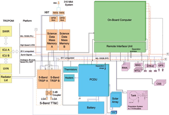
The core of the electrical & functional architecture is the satellite’s On Board Computer (OBC) and the Remote Interface Unit (RIU) that links the various platform sensors & actuators as well as the instrument to the OBC. The OBC is responsible for executing command sequences sent from the ground according to specified command times, it handles telemetry and telecommand functions (generating housekeeping telemetry, storing it and transmitting it to the ground via S-Band), it provides on-board time synchronization via a Pulse-Per-Second Signal from the GPS terminal, and it is in charge of system re-configuration.
The OBC directly manages the S-Band transponder which delivers housekeeping data to the ground, receives command sequences and provides a ranging link for orbit determination.
Sentinel-5P uses a pair of redundant MIL-1553 buses for internal communications. For units with Remote Terminals, the OBC sends commands directly on the bus; for other units, the Central Software delivers commands to the RIU (via 1553) and the RIU then relays them via the appropriate interface; standard High Power On/Off Commands are handled directly by the OBC.
The Sentinel-5P system design specifies a high-degree of autonomy, allowing the satellite to receive and execute command sequences for up to one week of operations and storing housekeeping data for three days. A dedicated 1553 bus connects the OBC to the Payload Data Handling Unit for commanding and payload housekeeping data exchange.
Employed as OBC is the well-proven LEON3-FT processor operating at 32MHz and capable of 22 MIPS (Million Instructions Per Second). A redundant science data mass memory of 512 Gbits offers volume for three orbits of science collection and separate system memory on the OBC side is used to store commands and telemetry.
The S-Band TT/C system hosts a pair of independent transponders connected to two Low-Gain Antennas through a coupler for command uplink at a data rate of 64 kbit/s and telemetry downlink at 571 kbit/s with ranging and coherency simultaneously. Payload data downlink occurs in X-Band – using a pair of QPSK Modulators and Traveling Wave Tube Amplifiers interfacing with a narrow-beam X-Band antenna, transmitting data at 310 Mbit/s.
TROPOMI Instrument
TROPOMI – the Tropospheric Monitoring Instrument – is the single payload of the Sentinel-5P satellite, featuring four spectrometers that operate in a pushbroom imaging mode, collecting spectral data from Ultraviolet to Short-Wave Infrared at very high spatial resolution to provide information on the local composition of the atmosphere with respect to gas constituents, clouds and aerosols.
TROPOMI is the national contribution to the GMES program by the Netherlands, being developed by several Dutch institutions, building on heritage from the SCIAMACHY and OMI instruments on the Envisat and Aura satellites, using the same measurement principle of passive sun backscatter spectrography but combining the best features of the two instruments: OMI is a pushbroom type sensor with a wavelength range of 270-500 nanometers while SCIAMACHY used a scanning concept but covered almost the entire solar spectrum. TROPOMI uses the wide-field pushbroom concept from OMI to obtain a high spatial resolution and retains the two-dimensional detectors from SCIAMACHY to operate across a similar wavelength range.

The combination of high-spectral resolution, high spatial resolution and daily global coverage enables TROPOMI to study troposphere variability, covering a number of relevant atmospheric constituents including ozone, nitrogen dioxide, carbon monoxide, methane and sulfur dioxide as well as aerosols and cloud properties like cloud pressure and cloud fraction.
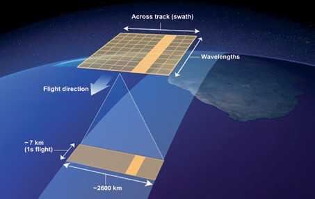
In essence, TROPOMI’s acquisition technique is imaging a strip of Earth with a two-dimensional detector for a period of one second during which the satellite moves by around 7 Kilometers. The strip is 2,600 Kilometers in the across-track direction (through the use of a wide angle telescope) and the along-track direction is 7 Kilometers. After a one-second integration, a new measurement is started, thus creating a progressive scan of Earth as the satellite moves. The two detector dimensions are used to resolve 7-Kilometer wide ground pixels in the across-track direction and for the different wavelengths. The small pixel size (high resolution) enables TROPOMI to measure natural and human-made sources and sinks of atmospheric gases including greenhouse products.
Defence and Space
Spectrometric measurements are based on DOAS (Differential Optical Absorption Spectrometry), measuring the absorption caused in the solar backscatter spectrum by constituents in Earth’s atmosphere down to trace gas levels. TROPOMI’s development, starting in July 2009, was led by Dutch Space as prime contractor and KNMI (Royal Netherlands Meteorological Institute) & SRON (Space Research Organization Netherlands) were in supporting roles for science definition and management.
The TROPOMI instrument has four specific mission objectives: a) constrain the strength, evolution and spatio-temporal variability of trace gas and aerosol sources impacting air quality and climate; b) assess processes controlling the lifetime and distribution of methane, ozone and aerosols to improve the current understanding of climate forcing; c) form long-term trends in the troposphere with respect to air quality and climate from the regional to global level; and d) develop and improve air quality modeling processes and data assimilation for operational services like air quality forecasting.

Defence and Space
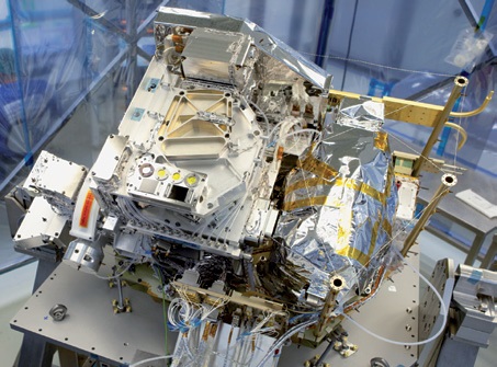
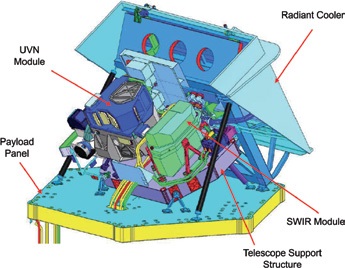
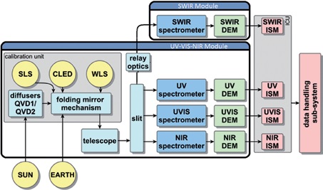
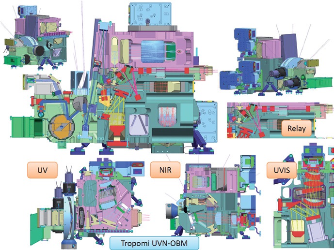
TROPOMI consists of four principal modules: the Telescope/UVN unit (containing the telescope and ultraviolet, visible and near-infrared spectrometers), the Relay/SWIR unit (with relay optics and the short-wave infrared spectrometer), the Instrument Control Unit (inside the satellite platform), and the Radiant Cooler.
All in all, TROPOMI measures 1.4 by 0.65 by 0.75 meters in size and weighs 206.6 Kilograms (+17.4 kg for the Instrument Control Unit), drawing an average power of 170 Watts and generating 140 Gbits of data per orbit. Typically, TROPOMI operates at a 89% duty cycle, capturing data on the vast majority of its orbit, only pausing for data downlinks and instrument maintenance.
The TROPOMI instrument uses a purpose-built telescope design, optimized for a large field of view in the across-track direction (swath), a reduction of polarization sensitivity and imaging in a broad operational range including very dark scenes down to 2% albedo.
Defence and Space
TROPOMI features a two-mirror telescope with concave mirror design – the primary mirror images a parallel beam from infinity (a broad strip in across-track) and the secondary mirror then images the strip onto the two entrance slits of the spectrometers with the spatial information resolved over the long direction of the slit. The instrument has a total of three slits, one for the SWIR unit and two within the UVN unit, one for the dedicated UV1 channel and a common slit for the rest of the UV/VIS/NIR channels.
A polarization scrambler is placed into the aperture stop between the two mirrors in order to reduce the polarization sensitivity of the instrument to less than 0.5%. Polarization scramblers are simple but effective devices to reduce polarization-effects to negligible levels compared to other, more complex methods like measuring polarization at some critical wavelengths and extrapolating for the entire measurement range.
A pair of limiting apertures are installed within the optical system, one acting as an actual field limiter in the swath direction while the other serves as a baffling aperture to eliminate stray light in the flight direction.
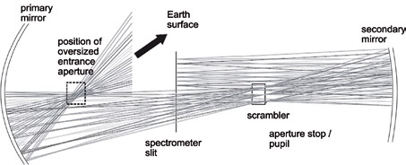
The two telescope mirrors are free-formed, non-symmetrical, aspherical mirrors to achieve the desired spatial resolution. The telescope has different focal lengths in the two perpendicular directions (along and cross-track) which is realized by dimensioning the aperture stop to a rectangular shape; the optics have different f-numbers by making the secondary mirror aspherical to yield the desired focal lengths for the spatial and spectral dimensions. These parameters have been chosen in a compromise between focal length difference and off-axis angles to extract the best overall performance – essentially creating a nearly perfect f-q system
The telescope has an entrance area of 25 mm² and the focal length is 34 mm in the spatial direction and 68 mm in the spectral direction, creating a spatial sampling distance of 0.125 degrees. The spectrometer entrance slits are 64 mm long and 0.56 / 0.28 mm in width for the UV1 and UVIS/NIR/SWIR spectrometers, corresponding to an instantaneous field of view of 0.48/0.24 degrees (spectral direction). TROPOMI’s optics deliver a telecentric image which greatly simplifies the spectrometers, allowing them to remain small in size through the use of folding optics to optimize their optical layout.
The UVN module hosts three spectrometers, the UV, UVIS and NIR which all use the same principle: light from the entrance slit is passed onto a collimator lens and then to a grating which separates the different wavelengths of the light in the spatial direction to allow each wavelength to be detected to a certain position on the detector. A set of camera foreoptics focus the spectrally separated image of the slit onto the 2D detector arrays.
The UVN module hosts two slits with an in-field separation so that the UV and UVIS channels can be optimized for proper performance in the 300 to 310-nanometer range where a number of atmospheric compounds have spectral signatures (e.g. chlorine monoxide, chlorine oxide, bromine oxide, sulfur dioxide and formaldehyde).
All three UVN spectrometers have identical 1024 x 1024-pixel CCD (charged coupled device) detector arrays using back-illuminated frame transfer technology with split readout registers. The focal plane is stabilized at a temperature of 208K in order to suppress effects by varying dark currents.
The split readout is realized by reading out half of the image in the spatial direction which enables different pixel binning to be used in the across-track direction. This feature allows two bands in the UV spectrometer to have a four-times lower spatial resolution below 300 nm as a measure to increase the signal to noise ratio.
For the NIR band – containing the important Oxygen A-Band at 770 nm – an optional increase in spatial resolution can be created in the across-track direction by reducing detector binning (improving the resolution in cloud information captured by the instrument, relevant for correction of other measurements).
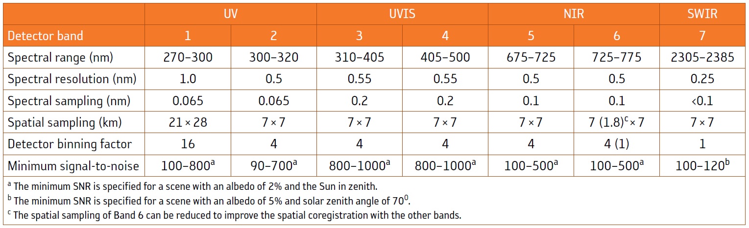
The UVN side of the instrument covers a total of six spectral channels: The lower UV band at 270-300 nanometers with a 1 nm spectral resolution and a 21 by 28 Kilometer spatial resolution (obtained by binning the detector pixels by a factor of 16 to increase signal to noise in favor over spatial resolution). The other UVN channels have a spectral resolution of 0.5 nm and a spatial resolution of 7 x 7 km (binning factor 4) covering wavelengths of 300-320, 310-405, 405-500, 625-725 and 725-775. As mentioned above, the NIR band at 725-770 nm can be operated in a non-binned mode to obtain a spatial resolution of 1.8 by 7 Kilometers in order to improve the spatial co-registration with the other channels.
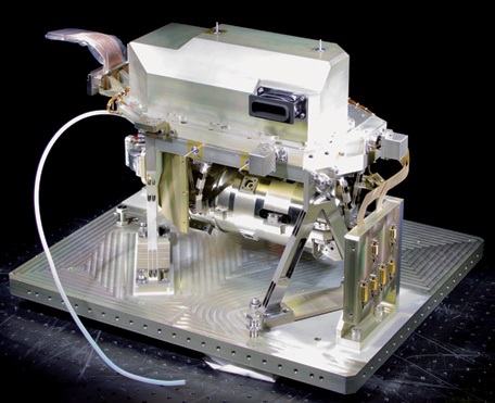
The SWIR module only holds one spectrometer unit, covering the 2305 to 2385 nm wavelength range in which the signatures of carbon monoxide and methane occur. As is typical for infrared-sensing instruments, the major challenge for SWIR was the requirement to cool the optics and focal plane of the instrument to reduce self-emission of the instrument.
Therefore, the SWIR module was isolated from the UVN optical bench and connected to a Radiant Cooler to keep the focal plane at 140 K. SWIR uses the same in-field separation as the UV side and a dichroic element separates the wavelengths with the UV being reflected to its respective spectrometer and the SWIR being transmitted and directed to its spectrometer via relay optics.
Optically, the SWIR side employs an entrance slit, an immersed grating, anamorphic prism, camera foreoptics and a CMOS detector array.
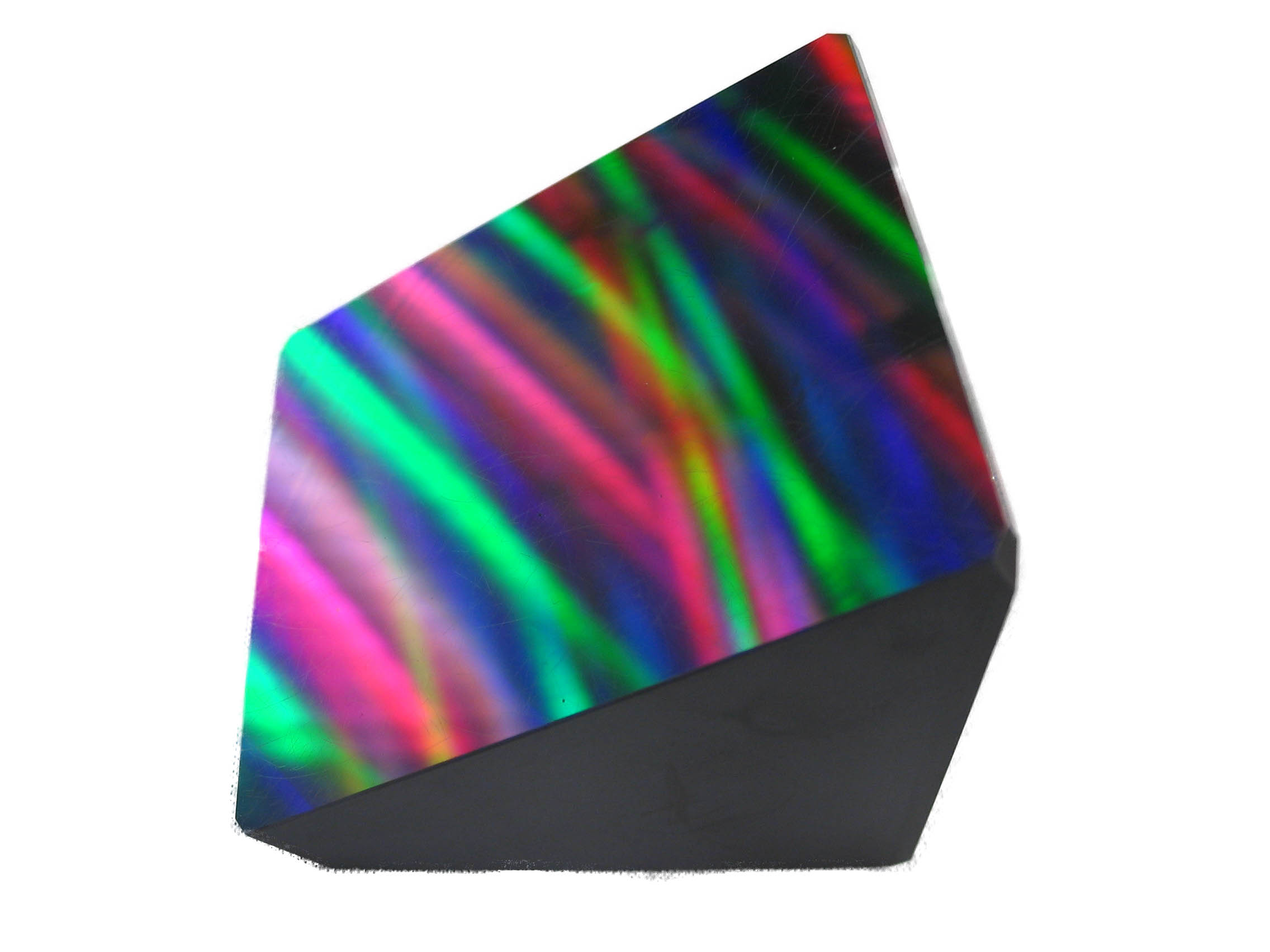
The need for a custom-developed grating arose from analysis using conventionally available gratings that showed the instrument would take unrealistic dimensions. Therefore, the choice was made to opt for an immersed grating – suspending the grating inside a medium with a high refractive index to reduce the wavelength of the light when traveling inside the medium and interacting with the grating.
Silicon, with a refractive index of 3.4, allowed the instrument volume to be reduced by a factor of 40 compared to a non-immersed grating. The 50 x 60-millimeter dispersive grating has a line density of 400 l/mm, a blaze angle near 55° and is used in the 6th order with an optical efficiency of 60%.
The SWIR detector comprises 1000 spectral pixels and 256 spatial pixels on a 30 µm pitch with a photo-sensitive layer of Mercury-Cadmium-Telluride on a Cadmium-Zinc-Telluride substrate hybridized by indium bonds to a silicon Read-Out Integrated Circuit. Conversion between pixel charge to a voltage occurs via Capacitive Trans-impedance Amplifiers and signals are clocked onto four parallel video output lines for transmission to the Front-End Electronics where analog-to-digital conversion occurs.

The SWIR spectrometer reaches a spectral resolution of 0.25 nanometers and does not employ pixel binning, obtaining a spatial resolution of 7 x 7 Kilometers at ground level.
The elaborate thermal design of the SWIR instrument calls for a hermetically closed instrument package with an anti-reflection coated silicon window as optical entrance and a molybdenum mount to the payload structure. An aluminum cold finger provides the connection between the instrument and the Radiant Cooler with the detector kept at 140 K and the rest of the spectrometer at 200 K.
A thin-walled Titanium double cone provides the structural connection between the focal plane and the warmer spectrometer assembly. Water vapor deposition (desublimation) onto the cold entrance window is prevented by the coating and deposition onto the detector is avoided by keeping the small volume around the detector vented to the vacuum of space through a PTFE vent line.
The SWIR Front-End Electronics (FEE) are responsible for commanding and powering the detector as well as reading out the analog output signals provided by four video outputs from the detector.
Digitization is completed by four 14-bit Analog-to-Digital Converters from where science and housekeeping data is then relayed to the Instrument Control Unit. The SWIR detector is read with a pixel speed of 800 kHz and a frame read time of 82 milliseconds, enabling the system to operate at a maximum frame rate of 12 Hz. The FEE are also responsible for fine thermal control of the instrument by reading a pair of temperature sensors and commanding thin-film heaters on and off, achieving a thermal stability of 6 milli-kelvin.
The Radiant Cooler is a three-stage cooling device providing the operational environments for all TROPOMI instrument units – the cold stage delivers a 140K temperature regime for the SWIR focal plane, the intermediate stage provides 205K for the SWIR optical assembly and 208K for the UVN detectors, and the warm stage keeps the UVN optical bench around 290K. All radiator stages are based on a heat pipe solution connecting the instrument components to a large external radiator. The cold stage radiator – a parabolic reflector – is inclined relative to the other two stages to achieve the thermal dissipation needed by the SWIR detectors.

The working fluids within the heat pipes vary between the three stages based on their desired temperatures – the cold stage employs methane, the intermediate stage ethane and the warm stage ammonia. A black radiative coating is used for the cold and intermediate stage while the warn stage uses optical surface reflectors.
A protective cover using an aluminum honeycomb sandwich shields the radiators for the first month of the Sentinel-5P mission to keep them at warm temperatures in order to avoid outgassing products from the satellite depositing onto the radiator surface which could impair its performance. In the open position, the door shields the radiator from Earth-shine.
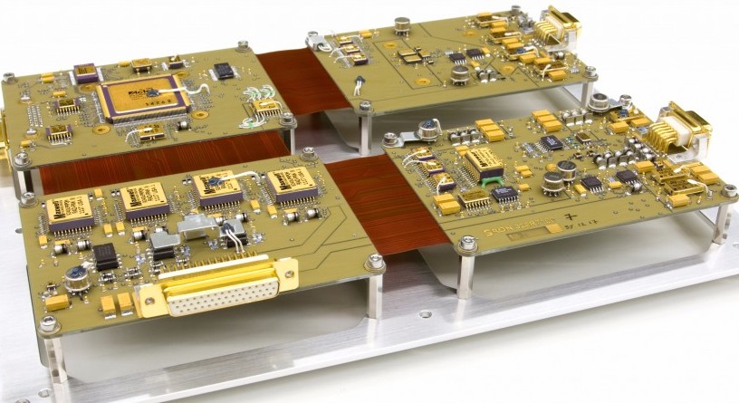
The Instrument Control Unit (ICU) is the single data interface between TROPOMI and the satellite platform, responsible for accepting and processing digitized data from the four spectrometer focal planes, forwarding processed data to the satellite mass memory, executing all functions of the instrument (commanding imaging sessions, defining detector clock patterns, actuating calibration sources, providing thermal control) and collecting engineering telemetry from the various instrument sensors and electronics.
The ICU accepts data from the four detector assemblies via 140 Mbit/s Channel Link Interfaces while the ICU-to-Science-Mass-Memory connection uses an 80 Mbit/s SpaceWire bus. Power required by the TROPOMI instrument will be 170 Watts on average and 382 Watts maximum.
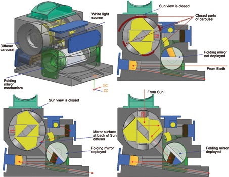
The TROPOMI instrument is outfitted with a calibration unit to ensure it can deliver precise data over the course of its planned seven-year mission using a combination of solar calibration and internal calibration via LEDs and laser sources. Internal calibration sources include well characterized White Light Sources (halogen lamps with bright spectral output), a Spectral Light Source, common LEDs and channel-specific LEDs placed close to their respective detectors. With common sources passing through the spectrograph and local sources close to the detectors, calibration can distinguish between detector-related degradation and degradation of the optics. Temperature-controlled laser diodes are used for calibration of the SWIR spectrograph only.

The solar diffusers – one for regular use and one for occasional exposures to remain in pristine condition – are employed to deliver direct samples of the well characterized solar spectrum to the instrument. Through the diffusers, solar irradiance is converted to even radiance for radiometric calibration while spectral calibration is completed with Earth and solar measurements.
TROPOMI has a highly flexible design that allows a number of parameters to be adjusted to obtain the best observation results. To avoid saturation, there are 25 detector readouts for each spatial frame and TROPOMI allows the user to set the exposure times with a step size of 1ms for UVN and 200µs for SWIR; the number of exposures to be co-added into the spatial sampling distance in the along-track direction can also be chosen freely. Pixel binning, already discussed above, also provides another flexible way of adjusting the image quality and lower binning factors can be implemented for the outer reaches of the detector arrays to improve data collected at extreme swath angles. Within the front ends, the CCD output amplifier gain and the Analog-to-Digital Converter gain can be set separately for each pixel row.
These flexible settings can be used to optimize the signal to noise ratio for different latitudes and solar angles as well as special cases such as ozone hole conditions.
Orbit & Ground Segment
The Sentinel-5 Precursor mission is designed to operate from a Sun Synchronous Orbit 824 Kilometers in altitude, inclined 97.74 degrees with a period of 101 minutes and a local time of ascending node of 13:35. This places the satellite five minutes (~2,300 Kilometers) behind the Suomi NPP satellite so that NPP’s VIIRS (Visible/Infrared Imager and Radiometer Suite) and Sentinel’s TROPOMI can collect quasi-simultaneous measurements of the same swath, generating a comprehensive data set between the two complementary instruments.
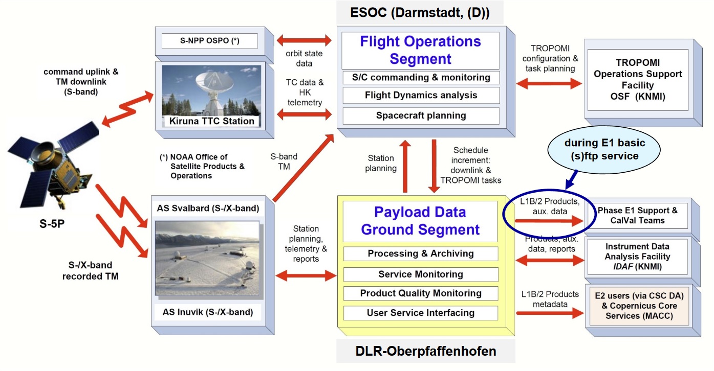
The Sentinel-5P ground segment consists of two major elements – the Flight Operations Segment (FOS) located at the European Space Operations Center in Darmstadt, Germany and the Payload Data-Processing Ground Segment (PDGS) at DLR Oberpfaffenhofen, also Germany. FOS is in charge of commanding, tracking and monitoring the spacecraft (essentially flying the mission) while PDGS is responsible for science planning, data acquisition, processing, archiving and distribution.
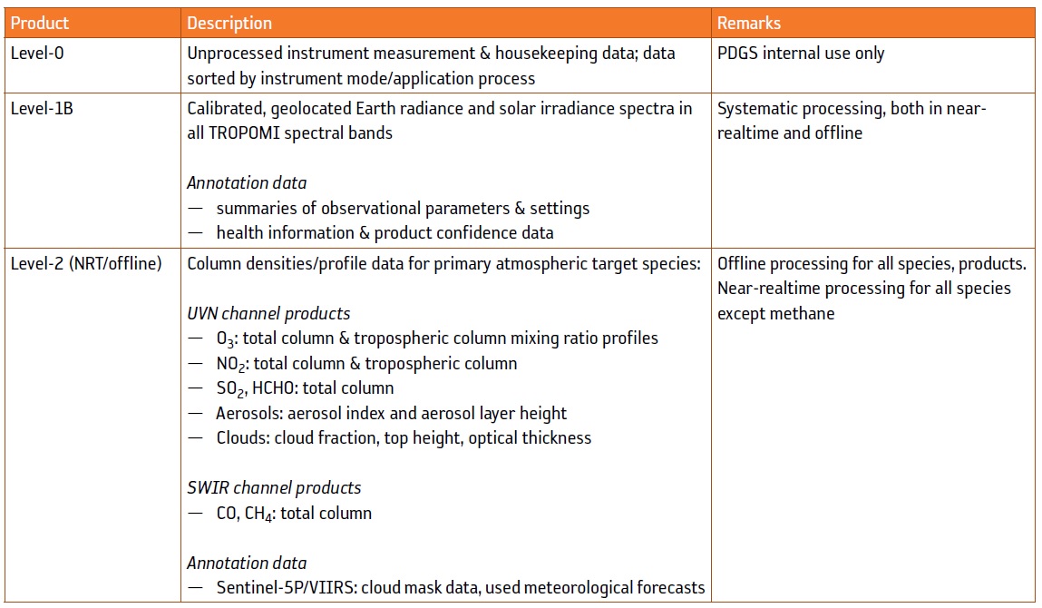
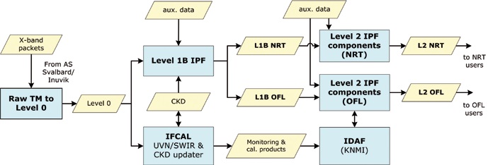
As a semi-operational mission, Sentinel-5P employs a fast data pipeline with data downlinks from the satellite to the Svalbard Station in Norway or Inuvik in Canada typically once per orbit and automatic processing into Level 1b and 2 data for fast distribution in a near-real-time scheme. Level 2 data products are maps of atmospheric constituent concentration, covering a total of 19 items for trace gases, albedo, aerosols, water and clouds.

