
Sentinel-3 Instruments
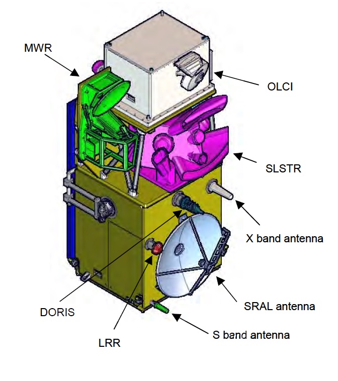
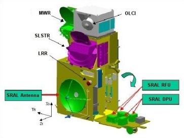
The Sentinel-3 component of the GMES Program is responsible for the collection of sea and land color data through the Ocean and Land Color Instrument (OLCI), sea and land surface temperature through the Sea and Land Surface Temperature Radiometer (SLSTR), and sea and land surface topography data using a Synthetic Aperture Radar Altimeter (SRAL) and Microwave Radiometer (MWR).
Additionally, data delivered by the instruments will come to use in land and sea ice assessments, ocean-current forecasting, sea-water quality and pollution assessments, as well as a number of land, atmospheric and cryospheric applications in an operational sense (e.g. fire detection, forest cover mapping, land use monitoring) as well as scientific studies requiring a continuation of heritage data in ocean and land monitoring.
The optical payload of the Sentinel-3 satellites is comprised of the OLCI and SLSTR instruments tasked with providing a simultaneous view of Earth for surface topography and temperature measurement and the generation of synergistic data products, exploiting the spectral channels of both instruments.
Ocean and Land Color Instrument – OLCI

The OLCI instrument of the Sentinel-3 satellites builds on the ocean and land color instrument flown on Envisat (MERIS) in 2002. Many improvements were made over the heritage design to optimize observation techniques and deliver more useful data products at greater quality. Some of the improvements include the increase of spectral bands from 15 to 21, a reduction of sun glint effects, a permanent use of the instrument’s high-resolution mode, improved coverage and a complete overlap of the instrument field of view with SLSTR.
OLCI is a pushbroom imaging spectrometer, meaning it sweeps out its images as the spacecraft moves across a given ground area, also extracting spectral information.
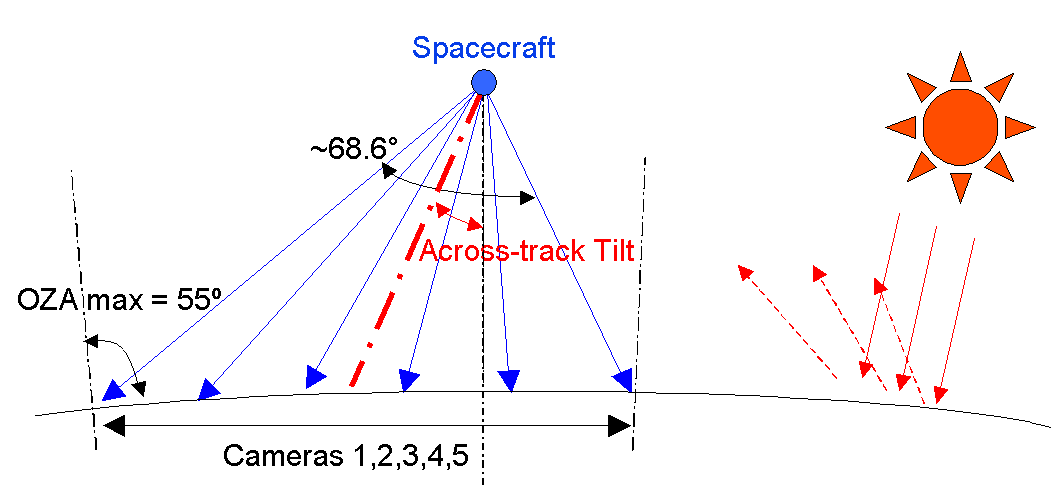
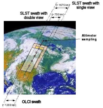
The instrument consists of five separate cameras arranged in a fan-shape sharing the complete field of view. In an improvement over heritage systems, the OLCI swath is not centered at spacecraft nadir, but tilted 12.6° to the west to mitigate sun glint effects at subtropical latitudes, a problem experienced by the MERIS instrument. Each camera provides a field of view of 14.2° with 0.6° of overlap between the cameras, generating an effective field of view of 68.6°.
OLCI covers a ground swath of 1,270 Kilometers to deliver a four-day revisit cycle when only one satellite is in use. The instrument covers an instantaneous field of view of 300 meters. Typically, sampling distance will be set at 1.2 Kilometers when passing over ocean and 0.3km for coastal and land observations. The mass of the OLCI instrument is 150 Kilograms and it measures 1.24 by 0.83 by 1.32 meters in size with a power demand of 124 Watts.
The main components of the OLCI instrument are the Calibration Assembly and Sun Baffle through which light enters the instrument and is passed to the Optical Bench from where it is focused on the camera detectors. A dedicated Video Acquisition Module for each camera extracts the detector read-out and completes initial analog to digital conversion tasks before relaying the data to the Optical Electronics Unit for onboard processing and transfer to the mass memory. The Optical Bench hosts five Focal Plane Assemblies feeding the cameras.
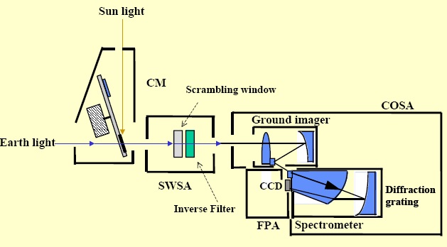

In each camera unit, Earth light enters a Calibration Assembly which includes filters as well as spectral calibration sources which are PTFE sun diffusers to track spectral calibration, gain calibration and instrument aging effects. Next, light passes through the Scrambling Window Assembly featuring a scrambling window and an inverse filter.
The Camera Optics Subassembly houses all optics needed for the separation of spectral bands and focusing the light onto the detector. After passing through the Ground Imager Optics, the light is dispersed by a diffraction grating and passed onto the Charged Coupled Device detector system building the centerpiece of the Focal Plane Assembly.
The spectrometer generates a dispersed image of the entrance slit onto a two-dimensional detector where one dimension is the spatial extension of the slit and the other is the spectral dispersion of the slit image created by the grating.
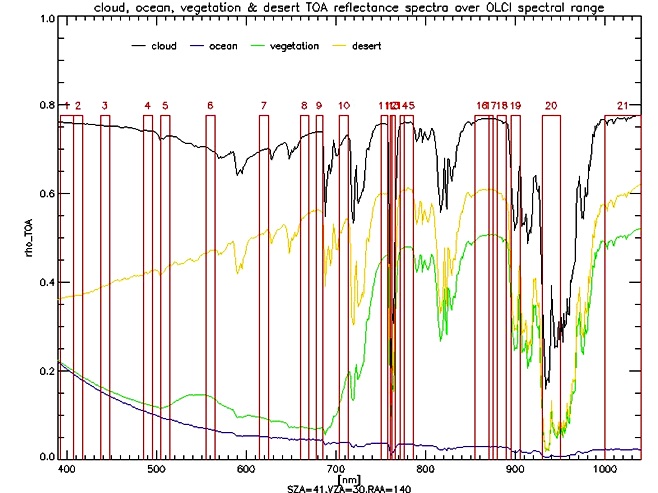
OLCI covers 21 spectral bands in the visible and near infrared wavelengths from 400 to 1020 nanometers, combining very narrow spectral channels of only 2.5 nanometers with wider channels up to a bandpass of 40 nanometers. The instrument supports signal to noise ratios suitable for the generation of ocean, land and atmospheric data exceeding the quality of the MERIS instrument.
OLCI has six added spectral channels over MERIS for improved atmospheric water constituent retrieval (400 and 673.75nm), aerosol measurement and atmospheric correction over coastal waters (1020nm) and improved retrieval of atmospheric parameters such as pressure and cloud top height in the O2A band at 760-775nm. The 673.75nm channel is also employed for chlorophyll fluorescence, supporting vegetation monitoring applications.
The OLCI instrument supports a re-definition of its spectral bands through a programmable acquisition design to support a high-degree of flexibility during the mission.
.
Sea and Land Surface Temperature Radiometer (SLSTR)
The SLSTR instrument is a next-generation Along-Track Scanning Radiometer covering a broad spectral range from the visible and near infrared into the mid-wave and thermal infrared to deliver comprehensive data on sea and land temperature, land color and fire detection.
The goal of the SLSTR instrument is to deliver sea surface temperature (SST) with an uncertainty of only +/-0.3 Kelvin for a 5 x 5° latitude x longitude area with high temporal stability of 0.1K per decade. Unlike the OLCI pushbroom instrument, SLSTR actively sweeps out its field of view as a cone segment to generate a wide observation swath.
SLSTR simultaneously employs two operational modes, each with its own specific viewing direction. In its dual-view mode, the instrument sweeps out a 55° cone segment in order to complete two scans of each location per pass. This operational mode uses a viewing direction to the rear of the satellite relative to its direction of motion, arising due to the need of sun observations by OLCI and SLSTR for calibration purposes, thus directing the mounting of the instruments on their shared instrument platform.

The second operational mode of the SLSTR instrument employs an asymmetric field of view around spacecraft nadir and only makes one pass per location in order to double the swath width. Dual-view scanning obviously comes with a higher precision of surface temperature, a requirement for data continuity with heritage instruments while the nadir view allows Sentinel-3 to fulfill its operational role of delivering rapid revisit times for global surface temperature measurements.
In its single-view mode, SLSTR covers a 1,400-Kilometer swath but only reaches a one-Kilometer spatial resolution while the dual-view scanning technique achieves an 0.5-Kilometer resolution, though only covering a swath of 744 Kilometers.
Single-view data is useful for climate and meteorology because it achieves a high revisit time of one day for one satellite and under half a day for the two-satellite constellation. The higher resolution data requires two days for a complete revisit (one satellite, 0.9 days for two spacecraft) but the quality of its data enables cloud screening and delivers advanced surface and atmospheric products.
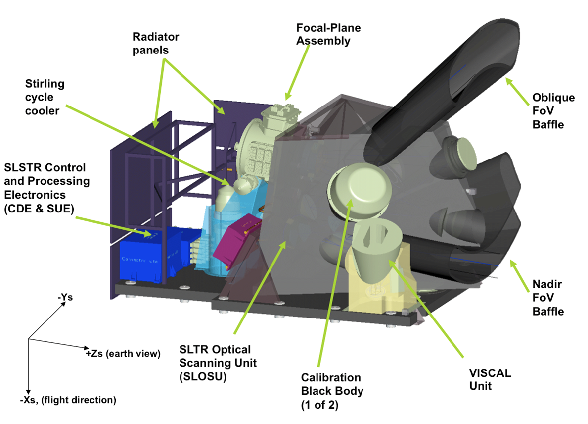
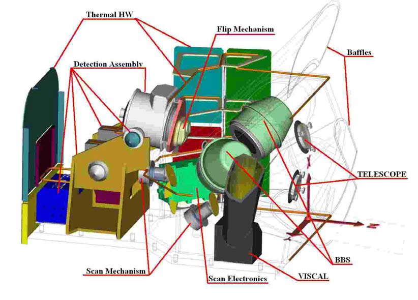
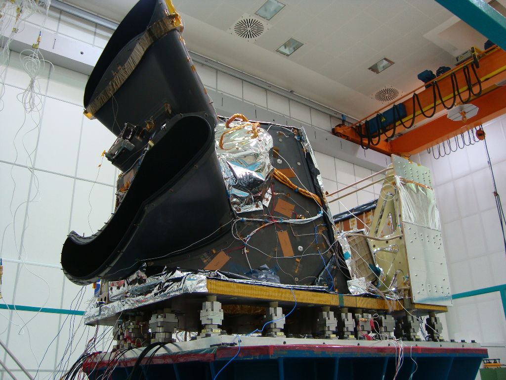
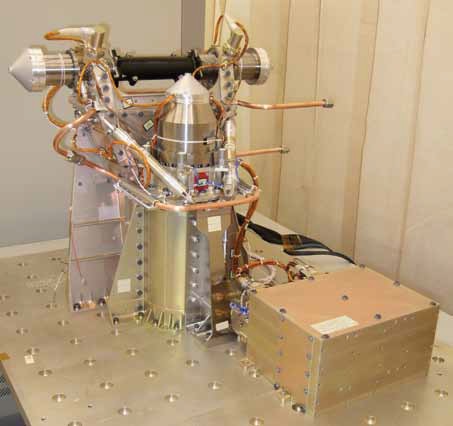
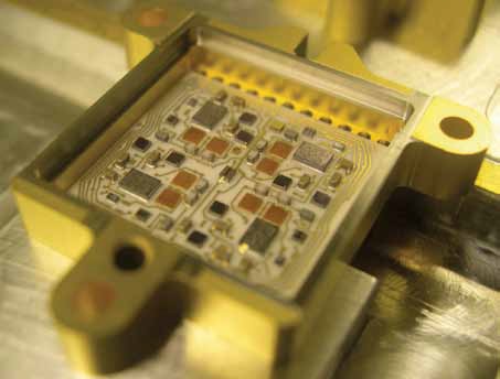
The principal components of the SLSTR instrument are the Optical Scanning Unit comprised of the Optomechanical Enclosure and the Detector Assembly, and a separate Control and Processor Electronics Unit.
The two Earth-viewing swaths are generated by two separate telescope and scan mirror assemblies and optically combined by a fast-moving switching mirror that delivers incoming radiation to the common focal plane assembly which hosts the detectors, covering three visible, three short-wave infrared, 2 mid-wave infrared and three thermal infrared channels. Within the Focal Plane Assembly, the infrared detectors are cooled down to 80 Kelvin by an active cryocooler to limit dark currents while the visible detector elements are operated at a constant, stabilized temperature.
Compared to predecessor instruments, SLSTR implements two additional channels in the short-wave infrared band for better cloud and aerosol detection needed for correction of surface temperature data and also to be used as stand-alone data products. Also, two additional channels for monitoring of fire and high-temperature events are part of the new system.
The three VIS channels supported by the instrument are at 555, 659 and 865 nanometers, each with a 20nm bandpass. The three shortwave IR channels cover the 1.375, 1.610 and 2.250 micrometer wavelengths with channel widths of 0.015, 0.06 and 0.05 microns, respectively. Mid-wave and thermal infrared science channels cover wavelengths of 3.75, 10.85 and 12 micrometers with spectral widths of 0.38, 0.9 and 1.0 micrometers. The two fire channels are at 3.74 and 10.85 micrometers, optimized for a broader temperature range up to 500 Kelvin.
The two scan chains are fully independent, each has its own scan mirror inclined 23.5° to the rotation axis, rotating at 200 rpm and sweeping out a full cone, feeding an off-axis parabolic mirror and folding mirror to focus the radiation onto the detectors. A fast-moving flip mirror selects which scan chain connects to the focal plane in a way that allows each chain to be optically coupled to the detector when sweeping across the relevant field of view and the calibration targets – requiring a great deal of synchronization between the optical chains.
The off-nadir scanner’s rotation axis is inclined backwards at 41 degrees, allowing the same ground swath of 740km to be observed twice with observation zenith angles under 55° – a requirement for the instrument to limit the radiance variations with sea emissivity changes caused by salinity, temperature and surface winds. The optical path length ratio between the nadir and off-nadir view is 1.54.

For every revolution, each of the scanners sweeps across two calibration targets which are two blackbodies, one at a 300K and the other at 265K to deliver precise performance data needed in data processing to achieve the target accuracy of sea and land measurements. Both blackbodies are outfitted with multiple thermal sensors to very precisely track their temperatures. Though the scanner sweeps across the blackbodies on every rotation, the measurement is only relayed to the focal plane every second revolution.
Another calibration source is a Visible Calibration Unit, illuminated by the sun for approximately one minute per orbit.
One of the most critical components of the instrument is the Flip Mirror Device FMD, responsible for the selection of the field of view that reaches the focal plane at any given time. With synchronized operation of the two scanner chains, the FMD has to ensure the nadir-rear looking chain is coupled to the detector twice per measurement cycle while the nadir scanner is connected once – all in a 600-millisecond period.
The FMD is a flat mirror with a 13-millimeter free aperture, held in place by flexural pivots. In its powerless setting, the FMD resides in its 0° position and when power is applied to the LAT motor actuator, the mirror transitions to its 15° position. Four switching operations are required for every measurement cycle and the FMD is designed for over two billion actuations, giving it a life expectancy over two decades.
The Scan Mirror Assemblies consist of the rotating scan mirror made from beryllium, attached to a scan drive encoder that controls the rotation speed. Both scanners are connected to Scan Unit Electronics in charge of the synchronization, performed to ensure a repeatability of 2 arcsec and a maximum position error of 6 arcsec to properly position the pixels within the field of view and maintain the two scanners in perfect synchronization. As an additional output, the electronics accurately measure the position of the mirrors at every synchronization signal in a 100Hz closed loop circuit for very precise geolocation referencing for each acquired pixel.
This type of measurement system maintains accurate geo tagging even in case of bearing torque degradation over the satellite’s operational life as well as angle errors due to electronic noise and other influences.
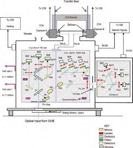
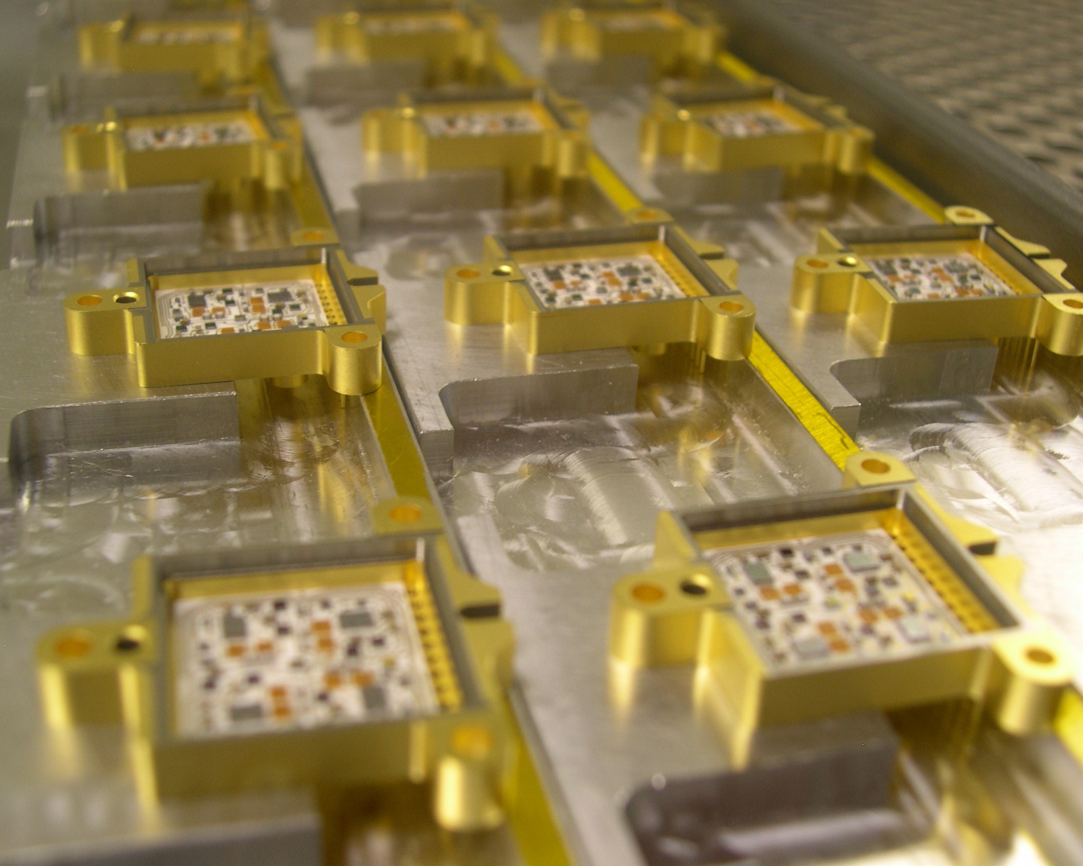
The SLSTR Focal Plane Assembly resides on a base plate and is housed in a cylinder and dome made of aluminum. Incoming beams are separated by wavelength using a series of dichroic elements that direct the appropriate beams to the nine detector assemblies.
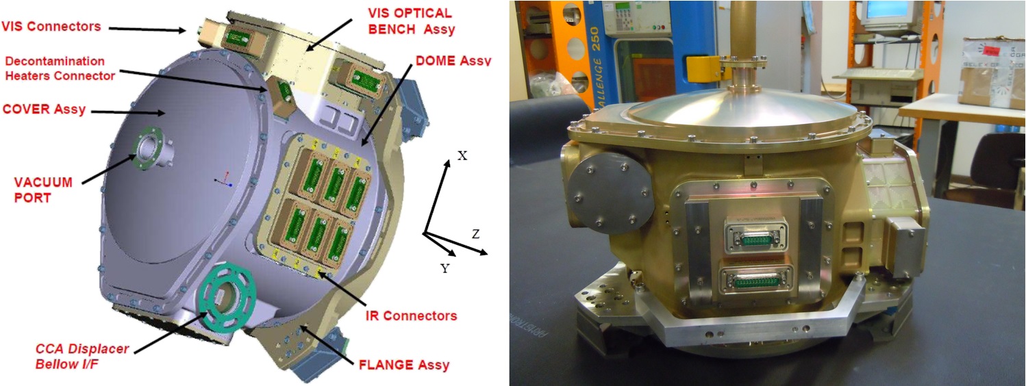
A cryo-optical bench facilitates all infrared detectors cooled to 80K to reduce dark currents while the VIS detector elements are located in a separate enclosure in the upper part of the Focal Plane Assembly and kept at a stabilized temperature of 260K. The cryocooler employs a space-proven design and has been optimized to comply with the low-vibration environment on the Sentinel-3 satellite.
The visible and near-infrared bands from 400 to 1,000 nanometers use photovoltaic silicon detectors mated to Trans-Impedance Amplifiers for high feedback impedance. Two different epitaxial layers and three anti-reflection coatings are implemented on the VIS detectors optimized for the target wavelengths to reach a uniform quantum efficiency of 80%. Each detector is comprised of four 185 by 205 µm elements.
Detection in short and mid-wave IR is accomplished with Mercury-Cadmium-Telluride photovoltaic detector arrays. The detectors are wire-bonded to readout integrated circuits for integration and multiplexing of signals with specific integrating capacitance set for each band to enable the detectors to operate at very low photo-generated currents even at their 40-microsecond dwell time. The detectors for wavelengths under 3µm consist of two columns of 100 x 100 µm detector elements while the 3.74µm channel only has one column of 200 x 200 µm elements.
The 3.74µm fire channel is realized using four pixels with an active area of 25 x 100 µm in order to even further reduce dark currents. The detector elements are installed perpendicular to the along-track direction. Given their purpose, the detectors leverage Buffered Direct Injection technology in their input stage to comply with a maximum temperature of 500K. The detector integrates the signal over its dwell time and a large capacitance enables the system to store the strong signals from hot targets at high temporal variations.
The infrared detectors are also set up to achieve an 80% quantum efficiency.
The thermal infrared channels over 10 micrometers employ HgCdTe photoconductive detectors for high responsivity to be able to minimize voltage noise. The detectors contain two pixels, each made with two pairs of elements, one active and one blind. All detectors are connected to their front-end electronics via a 1.5-meter cable harness.
The Front End Electronics subsystem is divided into a common and cold-redundant part. The common part regulates power supply voltages, receivers for the analog signals and systems for instrument thermal control while the second part comprises all functions associated with video processing of the incoming signals including amplification, filtering, correction, sampling and analog-to-digital conversion. It also generates instrument timing signals, housekeeping data and hosts data interfaces for command reception & execution and data transmission to the spacecraft. 20 analog signal chains are being managed by the instrument and put through three different analog processing methods depending on the wavelength channel.
Topography Payload
The second major component of the Sentinel-3 mission is the measurement of ocean and land topography, concurrently with surface color and temperature, in order to generate a comprehensive set of Earth observation parameters. The topography payload aims to deliver measurements over the open ocean, coastal areas, ice sheets, rivers and lakes.
Delivering data over the open oceans, Sentinel-3 will support the continuation of a record of permanent sea surface and significant wave height in cooperation with other altimetry missions operating under the Global Ocean Observing System.
The objectives of the Topography Payload are to continue and extend the altimetry measurement over open ocean started in the 1990s, to deliver along-track radar processing to improve data collected over coastal zones and inland water bodies, and to provide open-loop elevation data using an onboard Digital Elevation Model to improve acquisitions over inhomogenous terrain.
The two primary topography instrument are a SAR Radar Altimeter and a Microwave Radiometer – combining an active and a passive instrument. The active radar pulses radio signals to the ground and records the radar echo which can yield information on Ocean typography while a passive microwave radiometer only records the ambient microwave emissions at the given wavelength range to deliver correction data accounting for atmospheric effects.
To support elevation measurements, Sentinel-3 is equipped with GPS receivers for precise orbit tracking, also available in real time for onboard processing in order to support the rapid availability of base level data products. For more refined orbit determination, GPS data is put through ground processing and Sentinel-3 relies on orbit determination by the DORIS system and laser ranging. (See spacecraft overview “Orbital Determination Systems” for additional details). These supporting systems will improve the orbit knowledge from within three meters to within three centimeters to generate more precise Standard Time Critical and Non-Time Critical data products.
.
SAR Radar Altimeter (SRAL)
SRAL is a dual-frequency nadir-looking altimeter building the core instrument of the topography payload of Sentinel-3.
Operating at C- and Ku-Band, the radar transmits pulses to the ground and records the reflected echo in order to calculate the distance between the satellite and ground features, enabling it to measure ocean and land topography with an accuracy of a few centimeters – provided the orbit of the spacecraft is known with great precision, explaining the need for an elaborate orbit determination system utilizing multiple sources of data.
SRAL finds its heritage in a number of previous instruments flown on European missions including the Poseidon altimeters flown on the Jason altimetry satellites that will operate alongside Sentinel-3 to extend the record of ocean topography monitoring and incorporate this type of measurement into operational applications such as weather and marine forecasting.
The SRAL Ku-Band system operates at a frequency of 13.575 GHz with a 350MHz bandwidth as the primary radar frequency for surface height measurements while the 5.41 GHz C-Band system (bandwidth: 320 MHz) delivers data for ionospheric correction. Each radar pulse has a duration of 50 milliseconds.
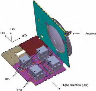
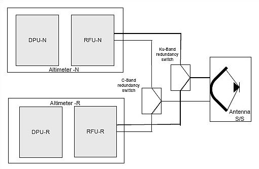
Both, the Ku- and C-Band radar, share a single nadir looking antenna dish on the +Z panel of the spacecraft, measuring 1.2 meters in diameter. A dual C/Ku feed horn is positioned in a centered configuration at a focal length of 43 centimeters with three support struts folding the feed in place. Two of the struts are doubled to improve sidelobe ratio performance while the third strut supports the Ku-Band waveguide. Overall, the antenna assembly has a mass of under seven Kilograms.
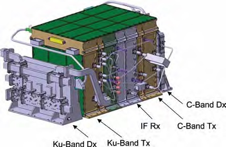
The electronics chain of the instrument is comprised of a pair of Digital Processing Units and two Radio Frequency Units, one for each frequency.
The SAR Radio Frequency Unit is in charge of initial signal processing, comprised of five slices that handle a range of different tasks along with the C- and Ku-Band duplexers that separate the two frequency domains. The Radio Frequency Unit up-converts the chirp signals from 50MHz to the desired C- and Ku-Band wavelengths at the nominal output power. The received radar echoes are sampled to 100 MHz and relayed to the Data Processing Unit.
The Data Processing Unit contains six boards to complete a specific set of tasks. The DPU delivers the 50 MHz chirp signals at the target Pulse Repetition Frequency. It also processes the echo signals transferred from the radio system, putting the signals through initial processing steps for digitization and transfer to the spacecraft via SpaceWire. Also, the system completes range and tracking processing of echoes in closed loop operation. For open loop operation, the system also manages the Digital Elevation Model required for the acquisition of this type of data. Finally, the DPU handles the 1553 connection to the satellite, executing onboard commands and sending out instrument status data.
SRAL can support two operational modes – a Low Resolution Mode and a SAR Mode for higher along-track resolution.
In the Low Resolution Mode, SRAL operates according to a fixed emission-reception sequence based on a static timeline characterized by a pre-set Pulse Repetition Frequency of 1920 Hz. This is the standard mode of operation of all radars, limiting the resolution to the distance traveled by the spacecraft between each pulse. SRAL’s pulse sequence calls for six Ku pulses per one C-Band pulse in a 3Ku/1C/3Ku scheme. This increases the resolution of the height measurement while still delivering sufficient ionospheric correction data.
The received echo is de-ramped and sampled on 128 points corresponding to a 60-meter range window. Fast Fourier Transformation is employed after the deramp to extract the required timing information. Ku and C band echoes are accumulated over a 50-millisecond period, corresponding to 84 Ku and 14 C-band pulses.
The SAR mode is implemented to achieve a higher along-track resolution through the use of Ku-Band bursts, either controlled in a closed-loop mode in which the range windows are positioned autonomously or open-loop mode putting to use global elevation models for a-priori knowledge of the terrain height. Each burst is composed of 64 Ku-Band pulses along with a C-Band pulse at the start and end with a pulse repetition frequency of 18kHz, placing the duration of one burst at 12.5 milliseconds. This will significantly improve the along-track resolution over the conventional operational mode. SAR Mode will be active in open-loop when passing over coastal ocean areas, ice sheet margins and rivers/lakes while closed loop will only come to use for sea ice measurements. The conventional Low Resolution Mode will be in use for measurements over the open ocean and the interior of large ice sheets.
In this operational mode, the instrument generates a data stream of 12Mbit/s, compared to the much lower 100kbit/s data rate of the standard mode of operation.
Microwave Radiometer MWR

The Microwave Radiometer instrument is a nadir-looking sounder that, unlike the active SRAL instrument, only records the natural microwave emissions from Earth and its atmosphere (=brightness temperature), not sending out a signal pulse to generate an echo. MWR is a dual-frequency radiometer operating at 23.8 and 36.5 K/Ka-Band with each channel covering a 200 MHz bandwidth.
The main task of MWR is to deliver atmospheric water vapor and cloud water contents within the field of view of the SRAL altimeter in order to deliver information for altimeter data correction. Atmospheric water causes a delay in the propagation of radio waves and thus affects the sensitivity of the radar measurements. Compensation through the use of a radiometer is only possible over the ocean where background noise is stable or areas where the background can be quantified, either through a third radiometer channel or analysis of the backscattered radar power. Over land and ice surfaces, meteorological data will be used to quantify the atmospheric water content.
The signal received by MWR is proportional to the abundance of the atmospheric component, in this case water, observed at the sensitive frequency. Through data processing, MWR delivers the time delay added to the altimeter pulses to account for atmospheric water content.
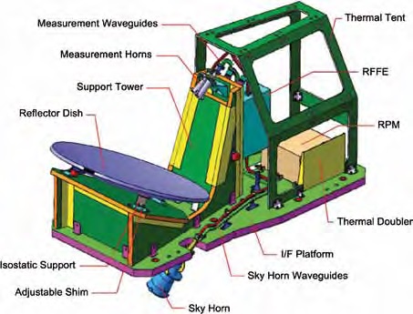
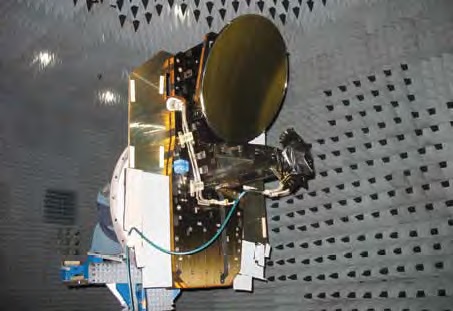
MWR has been built by Airbus Defence & Space CASA, Spain and consists of an antenna assembly, a Radiometer Electronics Unit, structural support systems and thermal control equipment. The instrument’s radio systems are fully redundant.
The MWR instrument assembly weighs 24 Kilograms and requires 26 Watts of power when in operation.
The Microwave Radiometer employs a single antenna reflector 60 centimeters in diameter and two separate feeds for the two channels plus another sky horn for calibration. Both antennas are sensitive for linear polarization and signals from each are transmitted to the front end electronics using separate waveguides. The Sky Horn is pointed towards the cold sky to deliver a calibration measurement with a diplexer system to separate the different frequencies.
Given the antenna geometry, the two channels have slightly offset footprints – the 23.8 GHz channel’s footprint is 23.5 km in diameter and pointed 1.98° into the along-track direction while the 36.5 GHz channel has an 18.5km footprint offset 1.93° in along-track
The Radiometer Electronics Unit REU is comprised of the Radio Frequency Front End directly interfacing with the feeds and the Radiometer Processing Module in charge of signal amplification, processing and conversion.
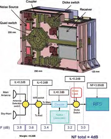
The Front End Electronics are in close proximity to the feeds to optimize the waveguide length for the desired radiometric performance. Facilitated within the front end are the amplifiers, calibration switches, and performance monitors. The Radiometer Processing Module hosts thermal control systems, front end controllers, noise injection loops and power supplies as well as communication interfaces with the spacecraft. Also part of the REU is in option to automatically blank the radiometer receiver inputs when the altimeter emits pulses to avoid disturbances. The Radio Frequency Front End is 20 x 29 x 12 centimeters in size and weighs 5kg, employing a Microwave Switching Assembly, redundant receivers and noise source for each channel.
The Microwave Quad Switches within the front end are used to select the nominal or redundant observation paths and switch between the nominal and redundant calibration paths through the noise injector which is comprised of a single noise diode isolated by cascaded PIN switches.
MWR is operated as a Noise Injection Radiometer – measuring the brightness temperature of the observed scene and comparing the noise captured in both channels to a very stable Dicke load generating a noise power equivalent to its temperature which can be precisely measured. This principle provides a reduction in the negative effects of receiver gain and offset instabilities.
Each three-part measurement cycle starts with a measurement of the scene with the addition of a known noise contribution, followed by a measurement of noise power of the current scene and then a noise measurement of the Dicke load.
The MWR instrument achieves a radiometric accuracy of 3K over a dynamic range of 150 to 313 K.
