
Schiaparelli Mars Lander (EDM)
Schiaparelli, or more formally known as the Entry, Descent and Landing Demonstrator Module (EDM), will demonstrate the technology needed for entry into the Martian Atmosphere, descending towards the surface and making a propulsive soft landing on the planet. This demonstration will pave the way for the 2018/2020 ExoMars Lander and Rover mission using technology demonstrated by the 2016 flight.
Schiaparelli rides to Mars aboard the ExoMars Trace Gas Orbiter launching in March 2016, supporting EDM with power and data connectivity through a seven-month cruise phase. Separating three days before arriving on Mars, Schiaparelli will be on its own and prepare for a landing at Meridiani Planum in October 2016. The primary objectives of the EDM mission are to demonstrate a landing in a controlled orientation and slow touchdown velocity, key technologies for the second ExoMars mission.

The lander has been named after 19th century astronomer Giovanni Schiaparelli who conducted an extensive study of the features of Mars.
EDM carries a small science payload comprised of an environmental and meteorological sensing system, and a descent camera. Only powered by non-rechargeable batteries, the lander will operate for about four sols on the Martian surface.
Originally, the Schiaparelli lander was to carry a more advanced sensor complement, referred to as the Humboldt payload with eleven instruments. However, in 2009, the lander design was de-scoped, canceling the Humboldt sensor suite. In its initial design, EDM was to be outfitted with a radioisotope thermoelectric generator to allow the lander to operate for a full year.
Carrying a number of sensors, EDM will take measurements of the atmosphere, the re-entry environment and the response of the vehicle to the various environments it will go through.
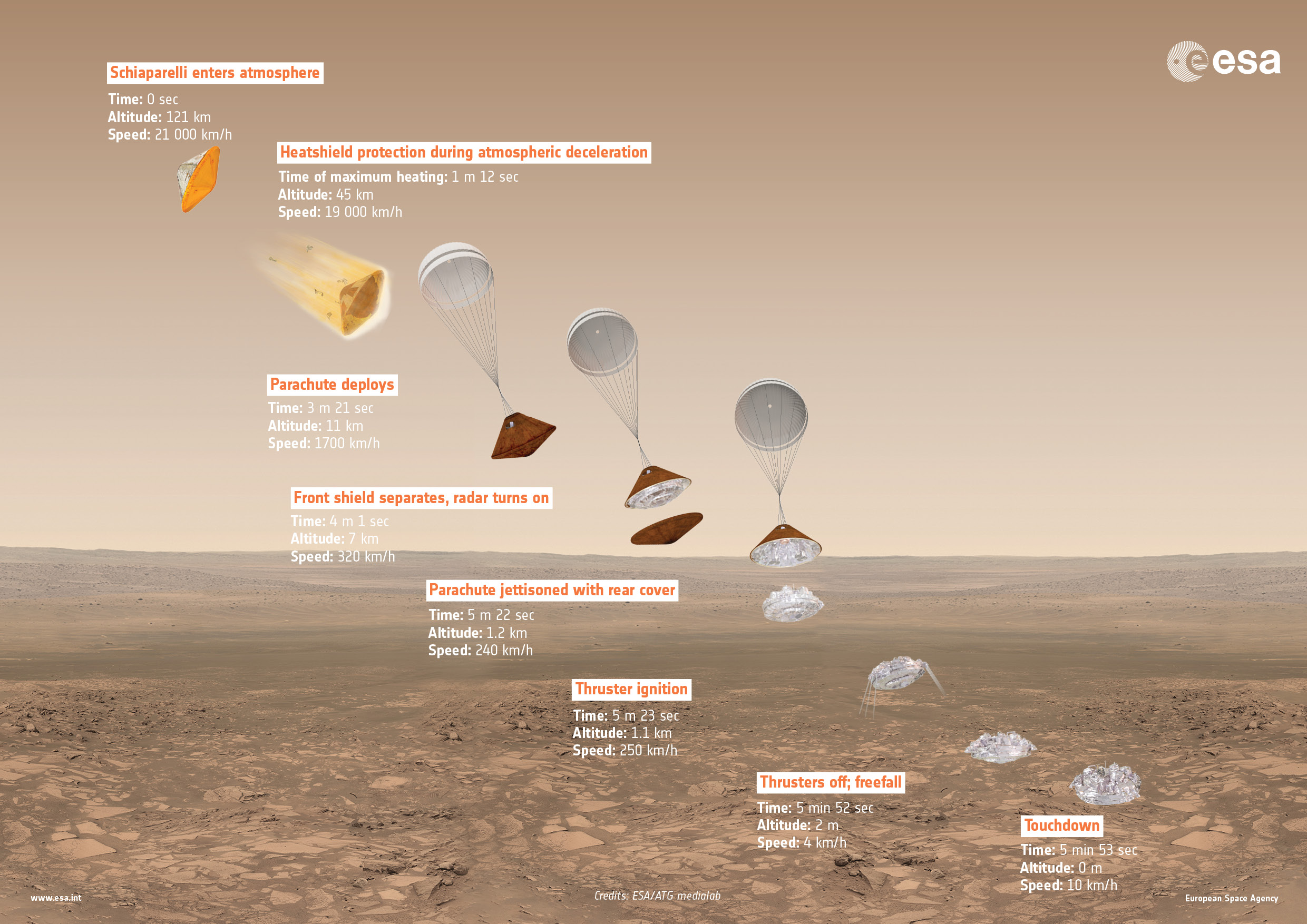
Up first during the landing sequence will be a heat shield to protect the lander from the extreme forces and heating occurring during entry – sensors will record pressures and temperatures experienced by the heat shield.
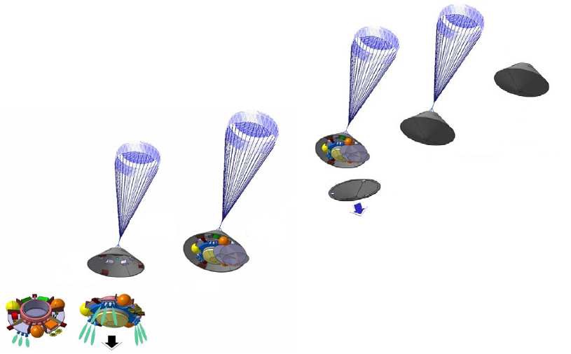
A 12-meter parachute will slow the craft down ahead of a propulsive landing sequence, completed in a Closed-Loop Control Scheme using a Radar Altimeter and Inertial Measurement Unit to deliver navigation data.
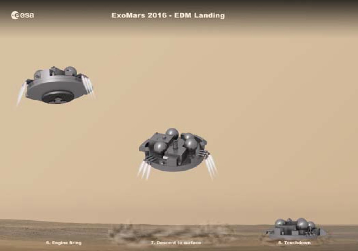
The final stage of the descent will use a propulsive landing system firing liquid-fueled engines to deliver the lander to a point one meter above the ground. At that point, the engines will shut down and EDM will drop to the surface, its impact cushioned by a crushable structure, designed to deform and absorb the landing shock.
Lander Design

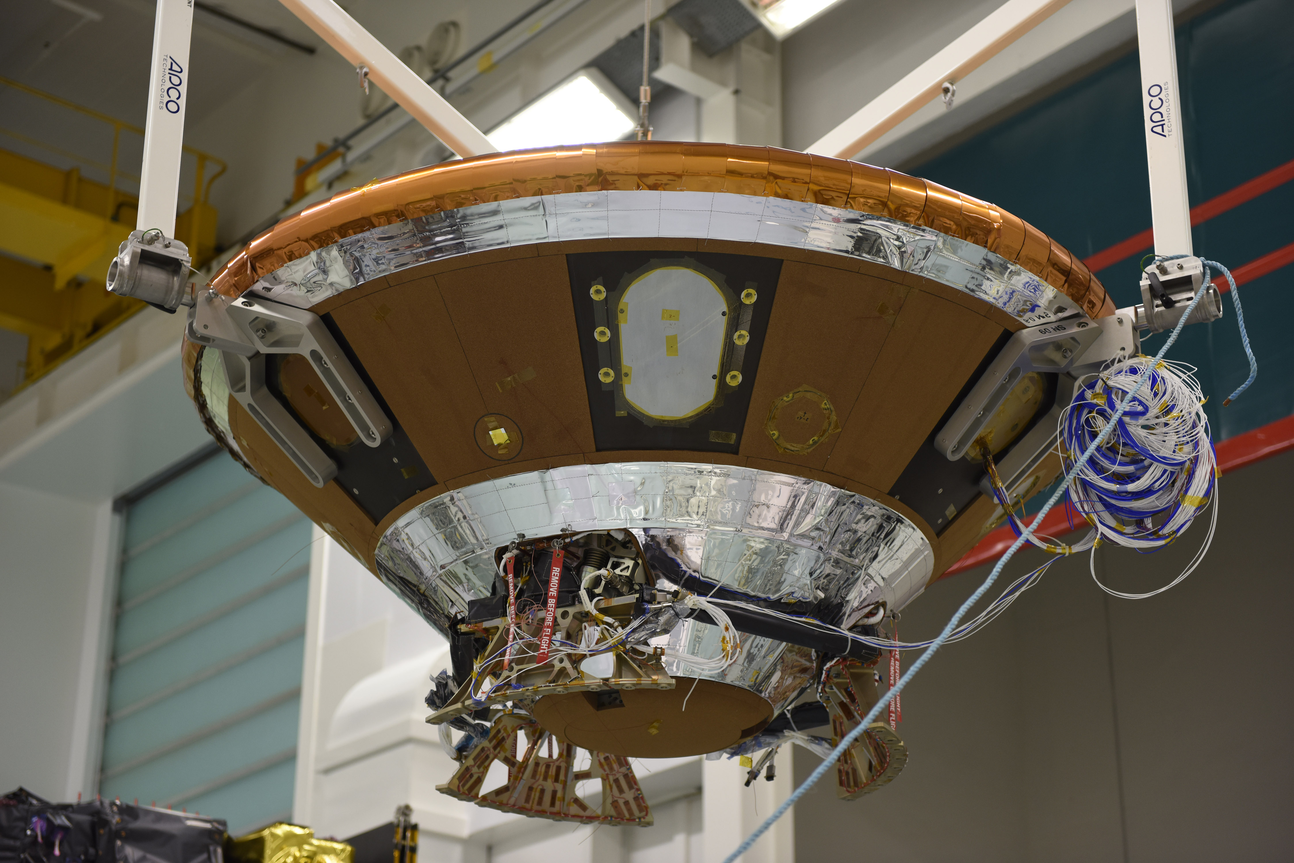
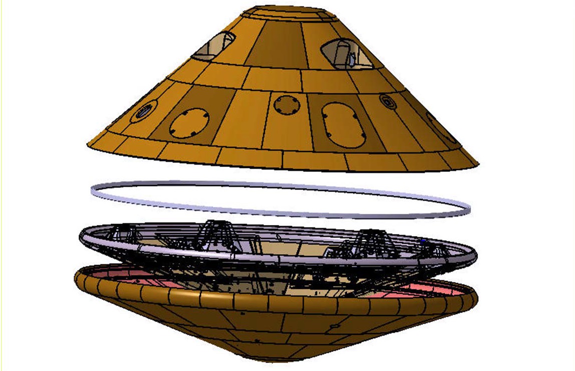
The Schiaparelli lander is based on heritage designs that have been evaluated as part of earlier ExoMars studies. The principal components of EDM are the Surface Platform, the Back Shield and the Front Shield.
Schiaparelli is 2.4 meters in diameter with its heat shield, 1.65 meters without, and it stands 1.8 meters tall. The total mass of the lander is 600 Kilograms. The Entry Vehicle has a 70-degree sphere-cone front shield and a 47-deg conical back shield.
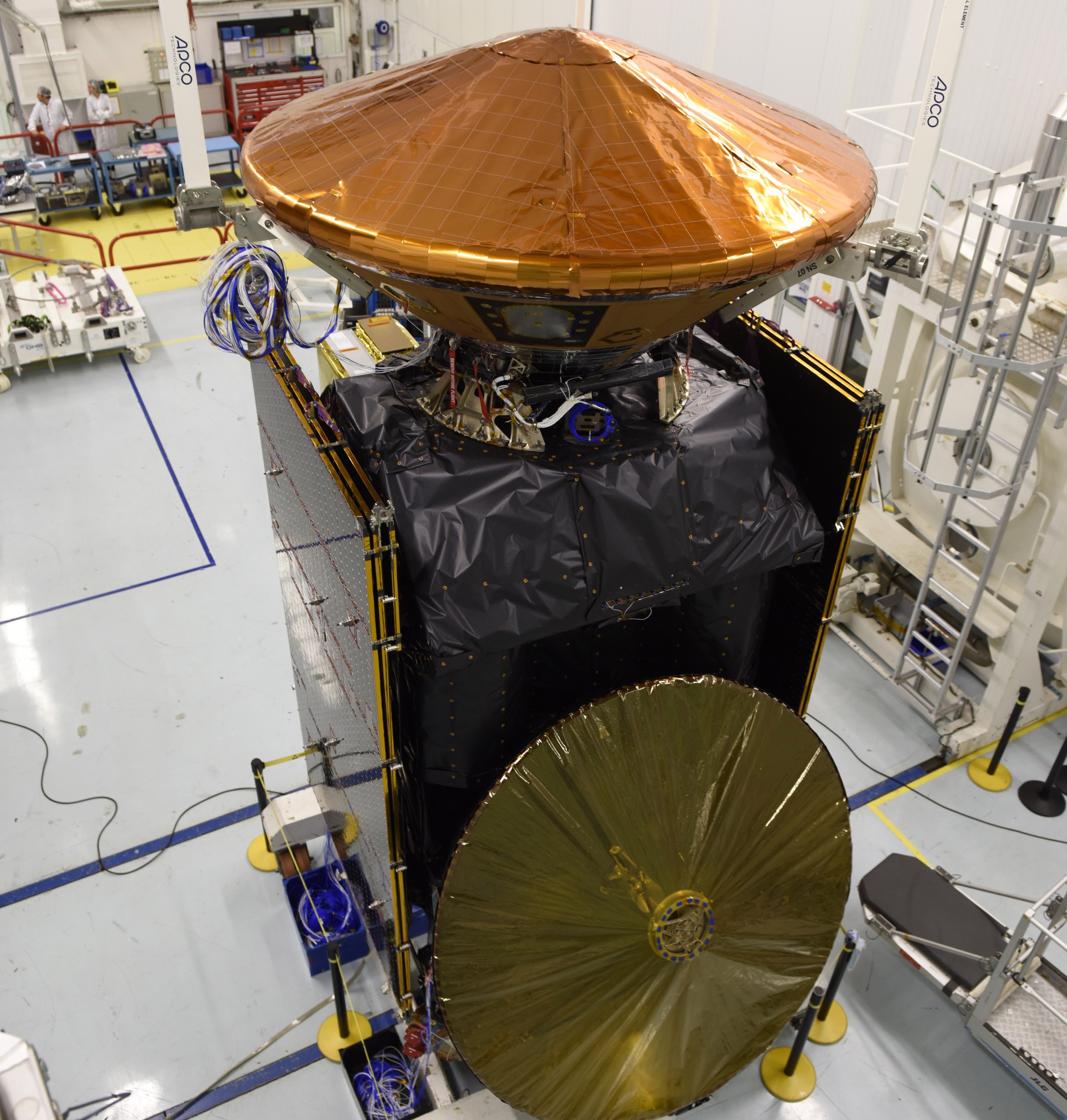
For the launch and cruise to Mars, Schiaparelli will be attached to the Trace Gas Orbiter – installed on a separation system on the Central Tube of the orbiter. Power will be transferred from TGO to EDM to keep the lander’s batteries at full charge until separation and hard-line data interfaces allow for data downlink from the lander through the orbiter to the ground and vice versa for telecommands.
The separation mechanism of the EDM lander includes a 3-point spin-up mechanism designed to deliver a 2.5 RPM spin-rate to the lander to stabilize it for its three-day flight to Mars. EDM and TGO are expected to separate at a relative velocity of 0.3 meters per second.
While in transit, the lander is operated in a hibernation mode to limit power drawn from the batteries. The hibernation starts shortly after separation and ends around one hour prior to re-entry to allow the lander to re-build its inertial reference frame from a dedicated sun sensor.
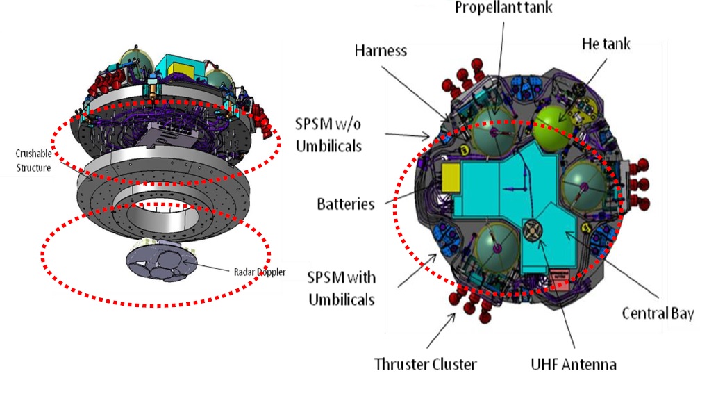
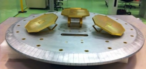
EDM’s structural components are made of Aluminum sandwich structure with Carbon Fiber Reinforced Polymer skins. The surface platform has a mass of 300 Kilograms and consists of a crushable structure on its bottom side, requiring all surface equipment to be mounted atop the platform. EDM employs a Warm Compartment hosting all systems that need to survive on the surface to maintain a safe survival temperature while components needed only during the landing phase are exposed since they are no longer needed after touchdown.
The Surface Platform hosts the EDM propulsion system, the Central Terminal Power Unit, primary batteries, and the 3-Kilogram surface payload.
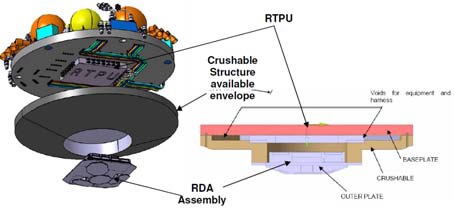

Installed on the bottom side of the Surface Platform is a Crushable Structure to act as a shock absorber during landing. The structure is attached to the Surface Platform via 6-centimeter stand offs and consists of aluminum sandwich panels that limit the deceleration at landing to 40Gs in order to guarantee the survival of all components atop the Surface Platform. The expected impact velocity is 4 meters per second.
The final impact attenuation system was chosen for its design simplicity as a passive system as opposed to controlled vented airbags or a high-fidelity sky crane system. Also, it allows a platform to land horizontally without necessitating protective covers which would be needed for a system relying on airbags for protection. This type of cushion permits direct surface access to a rover, not requiring a complex delivery system with ramps or moving parts.
Heat Shield
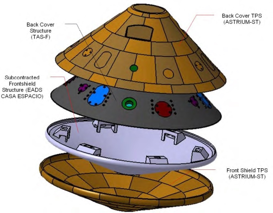
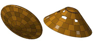
The EDM heat shield is divided into two components – a composite Frontshield Structure and the Front Shield Thermal Protection System applied to the structure. The Thermal Protection System employs Norcoat-Lige as heat shield material and has heritage from ARD, Beagle2 and Netlander. The entire Front Shield weighs 80 Kilograms.
The Frontshield Structure consists of an Aluminum honeycomb components with Carbon Reinforced Polymer Skins, making a robust but lightweight structure capable of holding the thermal protection material.
The Thermal Protection System is comprised of 90 tiles with seven different tile shapes and thicknesses, each consisting of outgassed Norcoat Lige bonded with silicone glue. Norcoat is an elastomer material combining a cork powder and phenolic resin ablator, applied at thicknesses of 8 to 18 millimeters depending on the areas on the heat shield. Heated on the outside to up to 1750°C, the Norcoat keeps the internal temperature underneath the material below 170°C and more insulation reduces internal temperatures to 50°C.
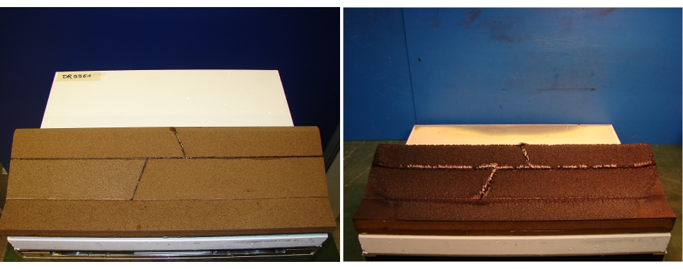
The principle behind ablative heat shield technology is to create a boundary layer between the shield’s outer wall and the extremely hot shock layer gas by allowing the heat shield material to slowly burn away and, in the process, generate gaseous reaction products that flow out of the heat shield and keep the shock layer at a separation distance, reducing the overall heat flux experienced by the outer shell of the spacecraft.
The processes occurring at the heat shield material include a charring, melting and sublimation on the one hand and pyrolysis on the other. Pyrolysis creates the product gases that are blowing outward and create the desired blockage of convective and catalytic heat flux. Radiative heat flux is reduced by introducing carbon compounds into the boundary layer gas which make it optically opaque.
EDM’s heat shield includes sensors to gather data on the re-entry environment, atmospheric properties and the response of the Thermal Protection System. These sensors include five surface recession sensors, seven thermoplugs, four pressure sensors and seven thermistors.
Back Shield
Schiaparelli’s Back Shield is made of two main components, a structure constructed from Aluminum Honeycomb and Carbon Reinforced Polymer, and a Thermal Protection System that, like the Front Shield, makes use of Norcoat Lige as TPS material.
The entire assembly weighs around 20 Kilograms and the Back Shield Thermal Protection System consists of 93 tiles with 12 different types of tiles, bonded with silicone glue. Sensors installed on the Back Shield are three thermoplugs and three thermistors. The maximum temperature expected on the Back Shield is around 710°C.
The Back Shield facilitates a UHF antenna for telemetry transmission during the Entry and Descent phase as well as a Sun Sensor required to determine the position of the sun prior to Entry to allow the onboard Guidance System to re-build its inertial reference frame for proper guidance and control during the landing sequence.
Parachute
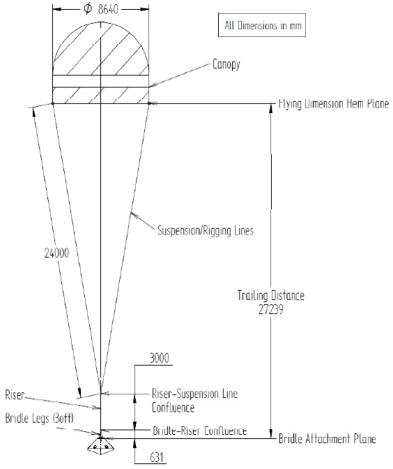
Schiaparelli employs a single-stage Disk Gap Band parachute with heritage from the Cassini Huygens lander. The Parachute System encompasses three main parts – the parachute, the parachute deployment device and the cover.
The 12-meter diameter parachute is deployed by a pyrotechnic mortar, ejecting the parachute bag with a speed of 30 meters per second and the folding technique of the chute & chords ensures a successful deployment.
Atop the mortar tube is an aluminum cover with thermal protection to tolerate the entry loads. Upon activation of the mortar, rivets within the Break-Out-Patch are broken and the patch is ejected together with the parachute bag. The Break-Out Patch carries its own 1.6-meter drogue chute to eliminate any possibility of re-contact of the descending lander with the cover.
The parachute can tolerate a speed up to Mach 2.1 and the chute trailing distance behind the spacecraft has been selected at 27.2 meters to avoid wake effects. The Parachute Riser is three meters long and the Suspension/Rigging Lines to the chute measure 24 meters in length.
Guidance, Navigation & Control
The EDM lander combines several GNC sensors to deliver the data necessary to complete the Entry, Descent and Landing phase. The primary guidance sensors are an Inertial Measurement Unit, accelerometers and a Radar Altimeter used in the final stages of the descent. Two sun sensors are needed to deliver information for the control system to re-build its inertial reference frame prior to entry.
EDM hosts a pair of Inertial Measurement Units for redundancy, operating at 200 readings per second. After the onset of entry and prior to the separation of the heat shield, Schiaparelli purely relies on the IMUs as navigation sensors.** The GNC function to trigger the deployment of the parachute uses an algorithm looking for the detection of an acceleration threshold to guarantee the chute is deployed in the correct envelope of Mach-Dynamic Pressure conditions.

The Radar Altimeter is a pulsed Continuous-Wave radar operating in the Ka-Band frequency range. It transmits un-modulated pulses to the ground and records the corresponding echo scattered from the terrain. The time delay can be used to determine the altitude above ground while a combination of delay and echo shape can be exploited to retrieve the slant range distance. Analysis of echoes from successive pulses yields the Doppler component.
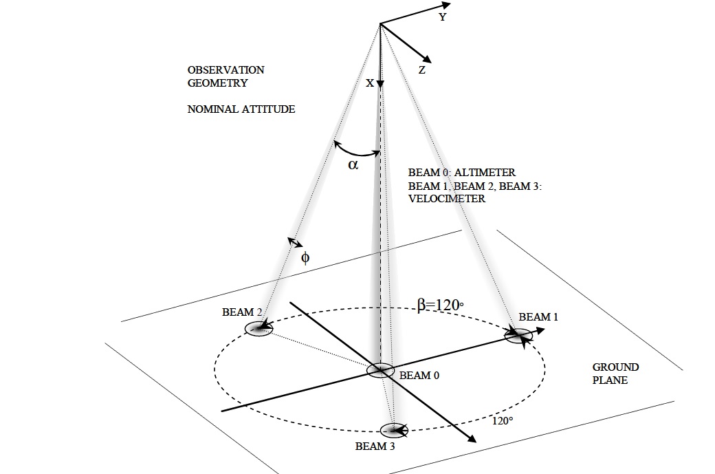
The Radar Altimeter facilitates four antennas interconnected by a switch matrix supporting a unique transmitting chain and a unique reception chain. One antenna is dedicated to range measurements while the other three are in use for velocity measurements.
The altimeter beam is directed straight down to deliver the current altitude above ground while the other three beams point to three separate locations in the along and cross-track direction to retrieve the different velocity components. The altimeter and velocimeter employ different observation parameters – pulse repetition frequency, pulse width, persistence time.
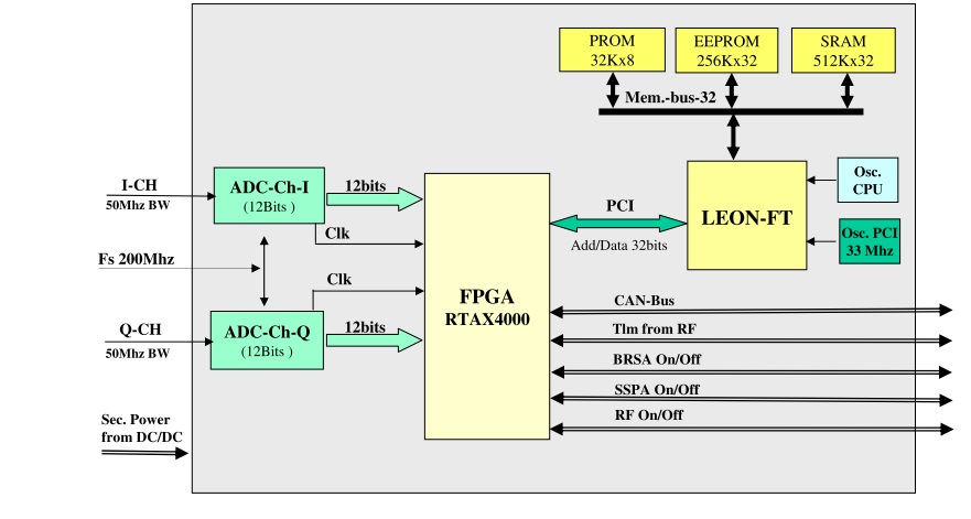
The signals from the antennas are put through analog-to-digital conversion before being processed by a Field Programmable Gate Array and a LEON-FT processing module that extracts the GNC information for relay to the spacecraft.
The radar assembly has a mass of 12 Kilograms and requires 35 Watts of power during its brief operation. It is installed on the underside of the crushable shock absorbing material and is not intended to survive the landing as its job is finished when the EDM has reached its engine cutoff point.
Overall, EDM’s GNC system achieves an altitude error of under 0.7 meters a vertical velocity error better than 0.5m/s, a horizontal velocity error under 1.05m/s and an attitude determination error under 5 degrees. As part of atmospheric entry, EDM purely relies on its inertial sensors because the radar can not become active until the Heat Shield separates.
Propulsion System

The Schiaparelli lander employs a propulsive landing system that comes into action after the Surface Platform separates from the Back Shell containing the parachute. The landing burn is performed by nine hydrazine-fueled engines operated in pulse-mode for a firing of around 30 seconds, starting at an altitude of 1200 meters.
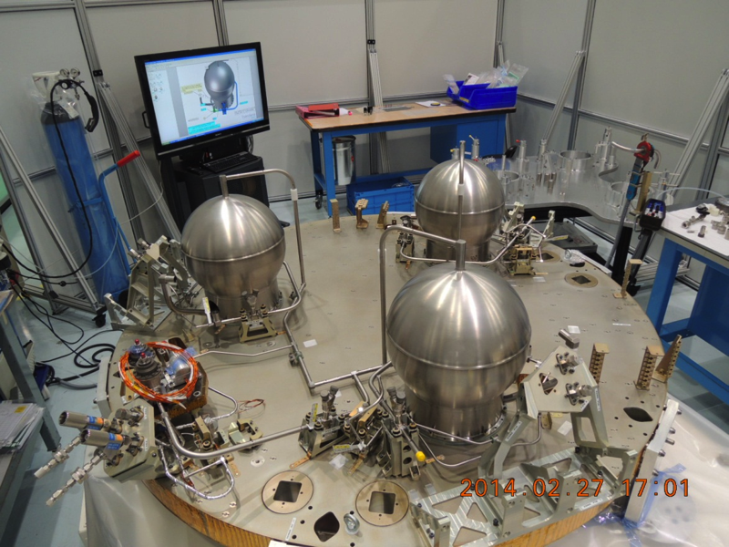
The propulsion system is comprised of a common pressurization system and three separate propulsion branches each with its own propellant tank and thruster bank. Downstream from the Helium tank is a pressure sensor and fill and drain valve allowing the tank to be filled with high-pressure Helium.
The pressurant line accommodates a pyrotechnic isolation valve, a two-stage pressure regulator and another pyro valve, opened shortly before the entry event to pressurize the system. The pressurant line then branches out into the three segments delivering pressurant gas to the three spherical Hydrazine tanks. Each of the tanks can hold up to 15.4 Kilograms of Hydrazine.
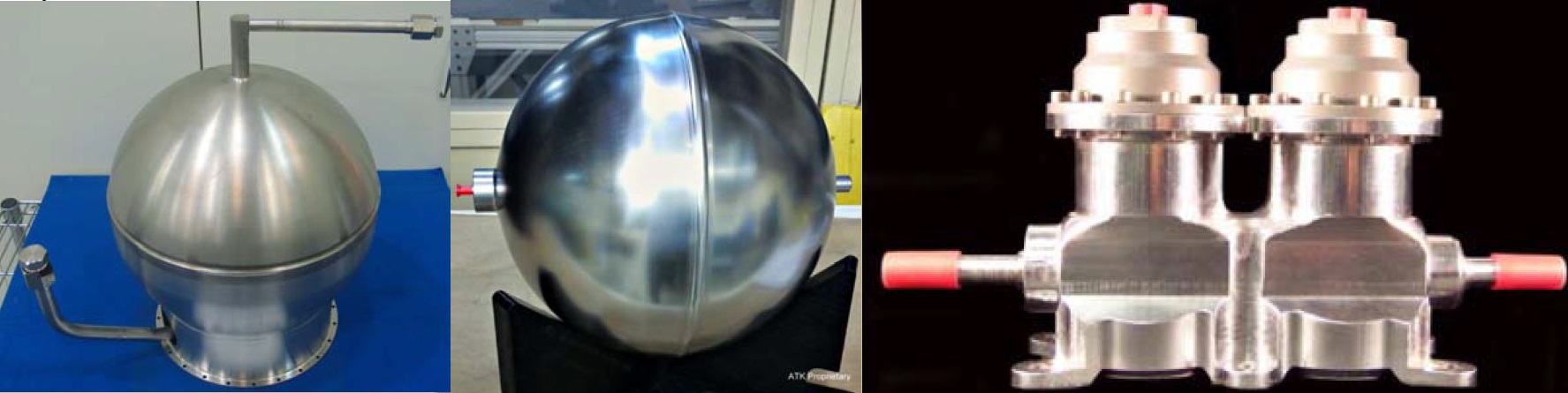
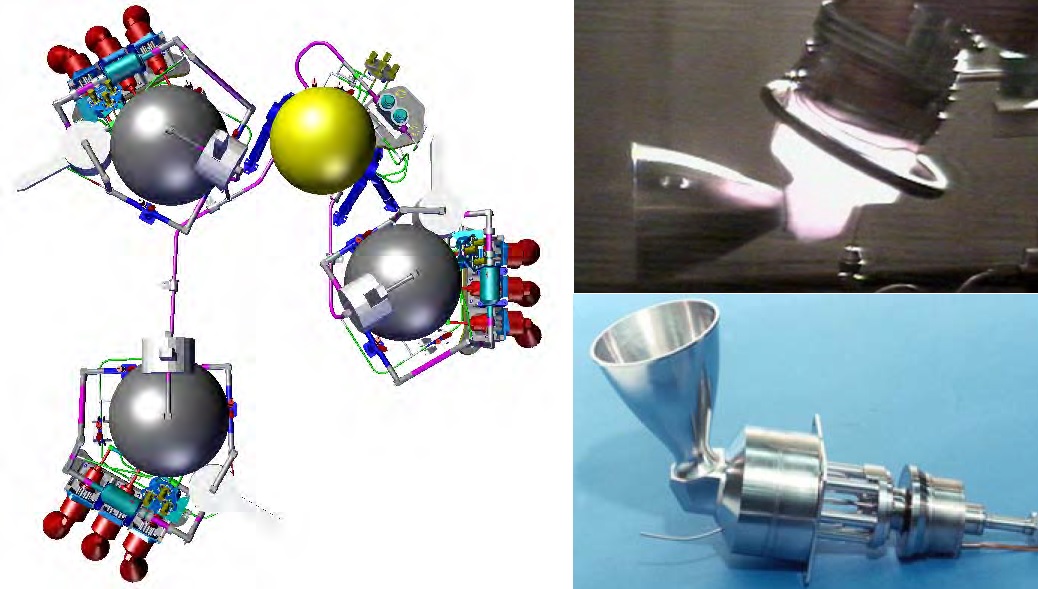
Each tank feeds a bank of three monopropellant thrusters with two pyrovalves and a filter located between the tank and the three thrusters, each hosting its own isolation valve. The central thruster on each bank points straight down while the two outer thrusters are canted to the side to reduce plume-to-terrain interactions. All three thrusters are canted to the outside from the Surface Platform to limit thrust losses due to plume interactions. The tilt angle also enables attitude control capability.
ExoMars uses CHT400 engines built by Airbus Defence and Space delivering a maximum thrust of 440 Newtons through the catalytic decomposition of Hydrazine over a heated metallic catalyst bed, yielding gaseous combustion products. The engines can be operated independently in pulse mode at 5 pulses per second, ensuring efficient attitude controllability.
The open and closing time of each engine will be commanded by the onboard computer based on radar Doppler and accelerometer data. Each thruster branch consumes approximately 700 grams of propellant per second.
The EDM Propulsion System delivers a total thrust of 3,600 Newtons to decelerate the 300-Kilogram Surface Platform from 250 to 7 Kilometers per hour.
The operational sequence of the Propulsion System starts with the priming, e.g. the firing of pyrovalves in the propellant lines to allow Hydrazine to fill the propellant lines to the fuel inlet of the engines. This takes place ahead of entry. Next is the pressurization of the propellant tanks, also by firing pyrovalves.
Electrical Power System

The Schiaparelli lander purely relies on batteries for its mission starting with the separation from the Trace Gas Orbiter.
Four different types of batteries are in use aboard EDM – a primary, non-rechargeable EDL (Entry, Descent & Landing) battery, a rechargeable EDL battery, a Surface Operations Primary Battery and a Surface Payload Battery. The first two batteries are installed on the exterior of the Surface Platform while the Surface Primary Battery and Payload Battery reside within the Warm Compartment.
The Rechargeable EDL Battery is comprised of three strings of cells and operates at 61 Volts while the Primary EDL Battery also uses a three-string layout, but operates at 33 Volts. The unregulated 60V bus is used to fire the various pyrotechnics (chute deploy, Front Shield Separation, Back Shield Separation, Propulsion System pyro valves) and it drives the thruster valves. The primary 33V battery powers the Entry Controllers, memory, entry sensors, thermal control system, etc. It is connected to the power bus shortly before EDM separation by closing a Depassivation circuit.
The efficiency of the Surface batteries is strongly dependent on their temperature. To ensure the batteries remain in a favorable thermal environment, they are equipped with temperature sensors and heaters.
To conserve power, EDM is transitioned to a hibernation mode shortly after separation from TGO and powers-up around one hour prior to entry to press into its final preparatory steps. In hibernation, EDM consumes around 7 W of power to keep its main computer operating as well as powering survival heaters. The wake-up of the lander is triggered by a triple-redundant timer system.
On the surface, the power budget is carefully managed through strategic operation of the instruments to maximize the science return of the mission. EDMs surface mission is expected to last around four sols before its batteries run out and the lander will go silent for all eternity.
EDM Functional Block Diagram
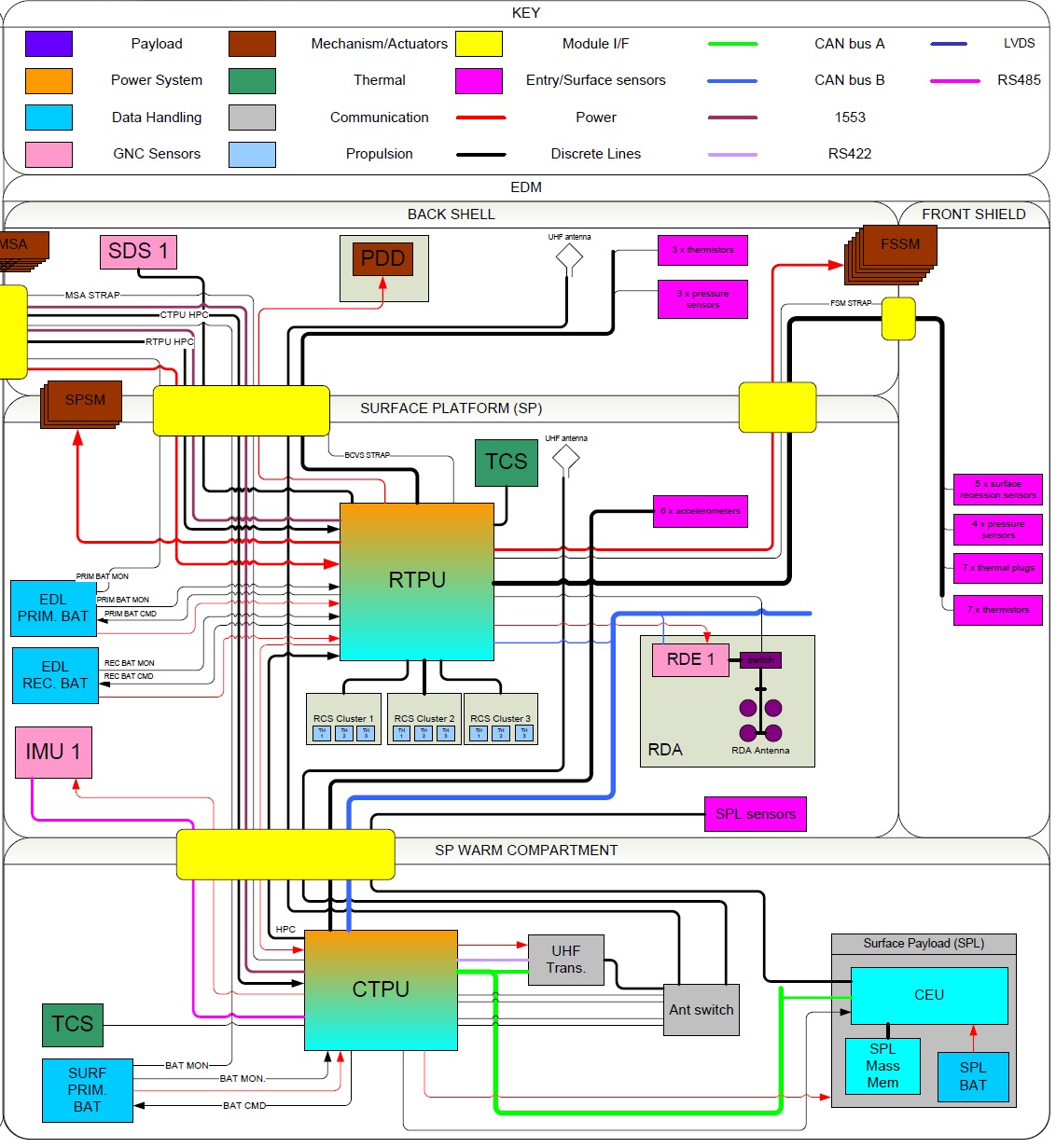
Data Handling and Communications

Within its Warm Compartment, Schiaparelli accommodates a centralized computer, the Central Terminal & Power Unit that is tasked with commanding all lander subsystems during surface operations, also directing power from the batteries to all powered components. It handles all onboard sequences, accepts science and housekeeping data, stores data and conditions data uplinks via UHF.
A second control unit, the Remote Terminal & Power Unit is installed on the underside of the Surface Platform and is in charge of the Entry, Descent and Landing Sequence – processing data from the GNC sensors, commanding the various separation events and parachute deployment, controlling the engines and distributing power from the two EDL batteries. It also builds the interface between the Trace Gas Orbiter and EDM during the joint phase of the mission – accepting power for use aboard the lander and exchanging data with the orbiter/ground.
The RTPU resides on the underside of the surface platform and is not designed to survive the impact at landing as its job end at the shutdown of the landing engines.

The CTPU is built around a LEON Central Processor that represents the heart of a Processor Module which also hosts RAM and PROM memory, the onboard timer, a watchdog timer system, power converters and data input/output interfaces.
An external Mass Memory is used to hold payload and housekeeping data until it can be downlinked, an external timer module includes three timers in a majority voting system and an Input/Output module builds the interface between the central processor and the lander payload.
The CTPU also includes an Electrical Power System accepting power from the battery and distributing power to the different systems. One CAN bus is dedicated to all systems of the Central Platform while the other is used by systems of the Propulsion Bay, the CTPU selects the current active bus.
Internally, the lander systems exchange data through two cold redundant CAN buses as well as serial buses primarily used between the Processor Module and the communications system.

Communications are handled exclusively in UHF using patch antennas installed atop the Warm Compartment of the lander and the Back Shell. The Back Shell antenna is used for the transmission of real-time data during re-entry in case the landing fails. This data is recorded by the Trace Gas Orbiter to have at least some data in case EDM does not phone home after landing.
The UHF system consists of an electronics unit, a UHF receiver and transmitter and a UHF patch antenna. Real time data is sent to TGO during Entry Descent and Landing and two subsequent 13-minute passes expected during the lander’s brief lifetime on the surface. These two passes will have to suffice for the uplink of 100Mbit of EDL Engineering and housekeeping data and 50Mbit of science data collected on the surface. NASA orbiters passing overhead during the surface mission can also be used for data relay.
**An earlier version of this article incorrectly identified the IMU used on the Schiaparelli lander and has since been corrected to reflect accurate information.