
RemoveDebris Satellite Overview
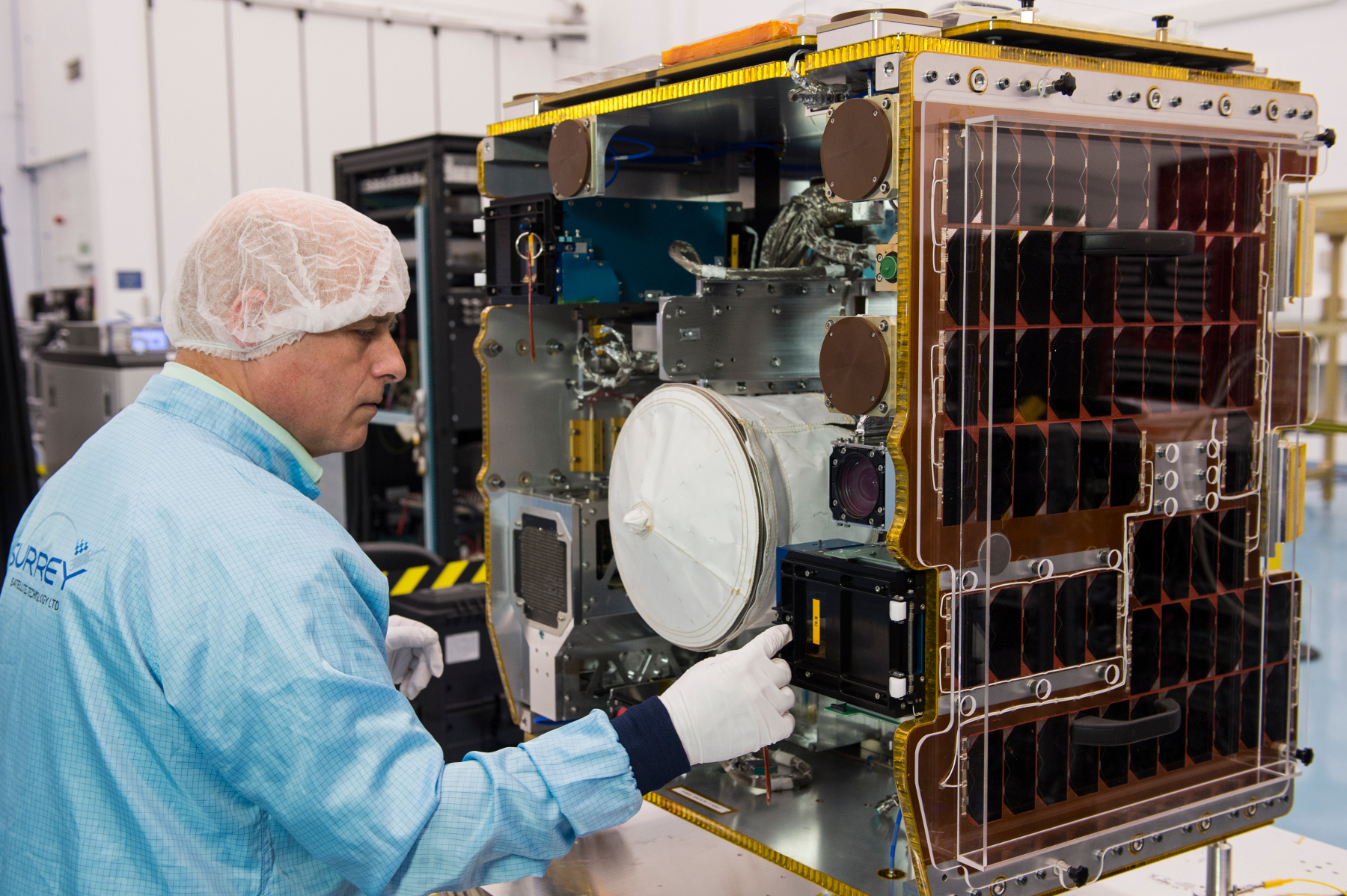
RemoveDebris is a small satellite mission by Surrey NanoSatellite Technology Ltd. under a European Union Framework 7 research project to develop and fly a low-cost demonstrator for the key aspects of Active Debris Removal missions on a quest to address the growing space debris problem. The 100-Kilogram, cube-shaped satellite – the largest deployed from the International Space Station to date (2018) – will demonstrate active debris removal techniques by releasing, tracking and capturing two small CubeSats called DebrisSATs, in the process demonstrating different rendezvous, capture and deorbiting techniques to evaluate their feasibility for operational debris removal missions of the future.
The RemoveDebris mission comprises three principal components: RemoveSAT, the parent spacecraft based on the SSTL-50 platform, and two DebrisSATs, both complying with the 2U CubeSat form factor. DebrisSAT-1 is to be captured by means of a deployable net while a harpoon-based capture system will be tested on a boom-deployed target. DebrisSAT-2 will serve as a target for an optical navigation/tracking system and RemoveSAT will be tasked with an expedited deorbit with a deployable drag sail once its mission ends.
ESA has taken a leading role in the field of space debris mitigation through a number of initiatives to develop clean space roadmaps and fund initial demonstration missions to acquire the tools needed for establishing an operational space debris management capability. These efforts are focused on two areas: a) debris mitigation through the removal of active satellites after their mission ends and b) debris mediation through the removal of passive debris objects. One particular area of focus is the removal of Envisat, an eight-metric-ton satellite in a near-800-Kilometer orbit that has been identified as a potential initiator of the Kessler Syndrome – a cascading formation of a large debris population making entire orbit regimes unusable.
The active removal of Envisat or any other sizeable space debris object is by no means a trivial matter and best completed as part of a step-wise evolution that allows for initial low-cost testing of technology and techniques in a realistic mission environment to reduce risk for the large-scale active removal mission. A number of elements are involved in active debris removal, including the need for optical rendezvous with a non-cooperative object, the secure capture of the object and the deorbiting technique for the combined spacecraft.
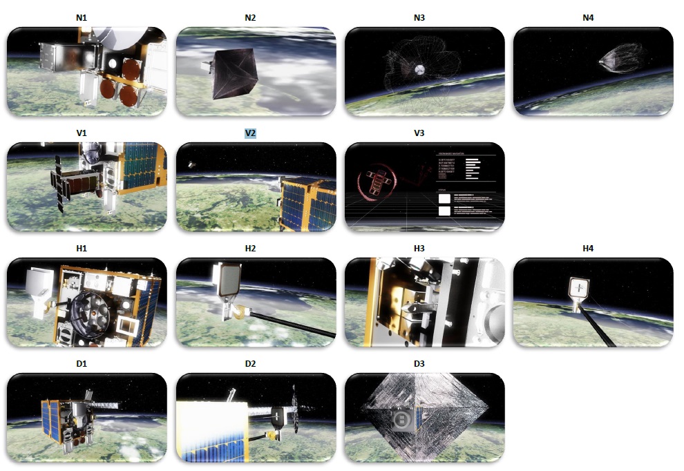
The primary objective behind the RemoveDebris mission is raising the Technology Readiness Level (TRL) for four elements: 1) a capture system based on a net, 2) a capture system based on a harpoon, 3) a Visual Based Navigation System (VBN) using optical, infrared and LIDAR imaging, and 4) a deployable drag augmentation device for rapid removal from orbit (drag sail).
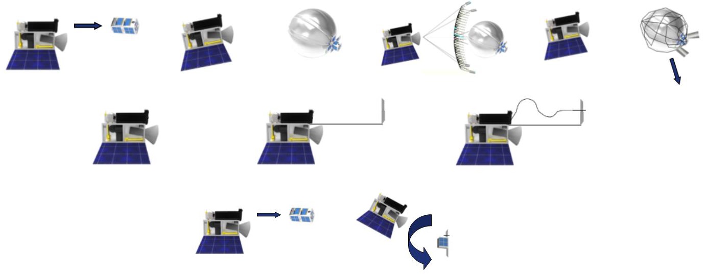
The net experiment to be performed by RemoveDebris will employ DebrisSAT-1, released from RemoveSAT at a relative speed of 0.05 m/s. The CubeSat will be tasked with inflating a balloon which increases its area to act as a deorbit device but also provides the “attack point” for the net. RemoveSAT will eject a net designed to wrap around the balloon by means of end masses and motor-driven winches to reel in the neck of the net and avoid re-opening. The CubeSat will then be left to decay on its own by means of increased drag.
The harpoon experiment was originally planned to fire at a CubeSat but the hardware was later changed to extend a 10 x 10-centimeter target assembly around 1.5 meters from the RemoveSAT satellite body and fire the harpoon at that while cameras document the activity. DebrisSAT-2, originally planned to be harpooned in, will instead be allowed to float freely to serve as a target for the VBN navigation exercise.
At the end of these experiments, the satellite will deploy a 10 m² drag sail to remove itself from orbit in an accelerated fashion and demonstrate the sail design for future operational missions.
The RemoveDebris platform employs Surrey’s SSTL-X50 satellite platform that builds on three decades of experience at SSTL to realize a low-cost satellite bus for a wide range of missions, satisfying the lifetime requirements for Earth Observation and LEO Communications operators.
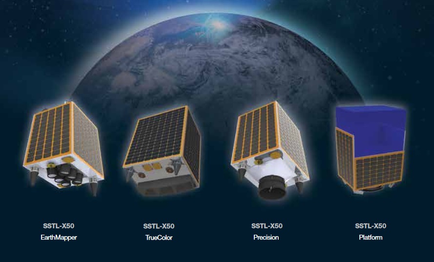
Initially, RemoveDebris was planned to employ the X50L configuration creating an envelope of 62 by 62 by 78 centimeters with a total mass of 150 Kilograms, but when it became clear the satellite would be launched from ISS, a reduction in size and mass was necessary to comply with the planned deployment using the Kibo Module’s airlock and the NanoRacks Kaber deployment mechanism – switching to the smaller X50 platform and eliminating mass by removing a cold-gas propulsion system and switching to a less massive separation panel in the aft of the satellite.
RemoveSAT measures 55 by 55 by 76 centimeters in size and weighs around 100 Kilograms, making it the heaviest satellite to be deployed from the International Space Station.
The X50 platform is based on four aluminum-honeycomb-sandwich side panels, a payload panel dividing the internal volume in two tiers, and a separation panel made from machined aluminum to build the primary load-carrying element between the satellite and launch vehicle. The side and separation panels provide the mounting structure for the various satellite platform systems while payload equipment is installed on the payload panel, the upper section of the side panels and atop the avionics bay.
Three of the four side panels are covered with solar cells to generate electrical power delivered to three Battery Charge Modules that control the central Li-Ion battery of the spacecraft from where power is distributed via three Power Distribution Modules. The typical payload power of RemoveDebris is 8 Watts with peaks during operation of the payload.
SSTL-X50 employs a highly modular power and data handling architecture, relying on a pair of card frames – one for the electrical power system and one for the bulk of onboard avionics, holding the central Onboard Computer, data storage, attitude control and communication cards with backplane interconnections. This design approach provides a high degree of modularity while also simplifying manufacturability, integration and testing as well as redundancy – possible through the simple duplication of the relevant cards. The use of central card frames also reduces the mass of the cable harness used by conventional systems and reduces complexity and failure points.
While the use of CardFrames is a new element introduced by SSTL-X50, the rest of the satellite’s systems rely on flight-proven components that have been used on previous SSTL platforms including attitude determination and control, communications and power systems.

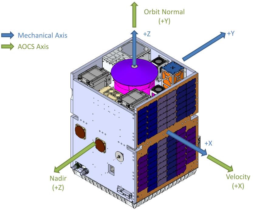
The vast majority of RemoveDebris platform systems reside within the lower tier inside the satellite body, leaving the upper half of the spacecraft completely free for use by the various payload components including deployers for the CubeSats, the net, the harpoon and the drag sail which all point to the satellite +Z axis (the Orbit Normal Vector +Y).
The Attitude Determination and Control System of the RemoveDebris satellite uses reaction wheels and magnetic torquers as actuators and a suite of magnetometers, sun sensors and gyros for attitude determination to keep the satellite flying in its duty attitude with reasonable accuracy (allowing a stellar-free navigation scheme to be employed).
Four 100-SP-O reaction wheels are the primary attitude actuator, arranged to be able to tolerate the loss of one wheel without impact on satellite attitude control. The reaction wheels are 13.1 centimeters in diameter and 12 cm tall with a mass of 2.6 Kilograms.

They are rated for 7.5 years of LEO operation and support a broad thermal environment. The RWA uses oil-lubrication and can deliver a maximum torque of 110 mNm which corresponds to a peak power demand of 113 Watts at max. torque. In standby mode, the wheels require 1.2W of power and the on-orbit average is around 10W. The wheels spin at up to 5,000RPM, limited by micro-vibration requirements.
The magnetic torquers chosen for Remove Debris are SSTL’s MTR-5, each measuring 66 x 252 x 39 millimeters in size, weighing 500 grams and delivering a magnetic moment of +/-6.2 Am² at a power consumption of only 1 Watt. Magnetic Torque Rods create angular momentum by running a current through coils in the presence of Earth’s magnetic field. The torquers are regulated by computers that control the current that is passing through the coils in order to control the force generated on each axis. The magnetic torquers are used during momentum dumps and for attitude control in spacecraft safe mode.
Two AOCS Interface Modules are tasked with collecting and pre-processing data from the various actuators and delivering it to the central Data Handling System where commands for the actuators are conditioned.
RemoveDebris relies on an SGR-20 Space-Based GPS Receiver and four patch antennas for position determination, precise orbit determination and time synchronization across the satellite.
The Onboard Data Handling Subsystem, facilitated within the OBDH CardFrame, consists of two redundant OBC750 onboard computers tasked with command and control of all satellite functions and a pair of redundant Payload Interface Units (PIUs) responsible for commanding of the various payloads and processing their data for storage and downlink. Additionally, a General Purpose Input/Output Board provides the interfaces with the various satellite subsystems through a CAN and LIN network and a Payload Power Supply Module conditions the payload-specific voltages.
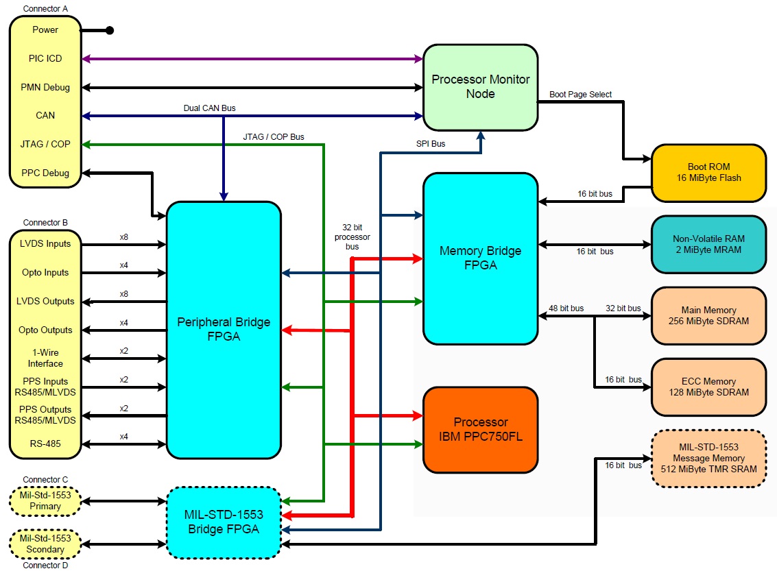
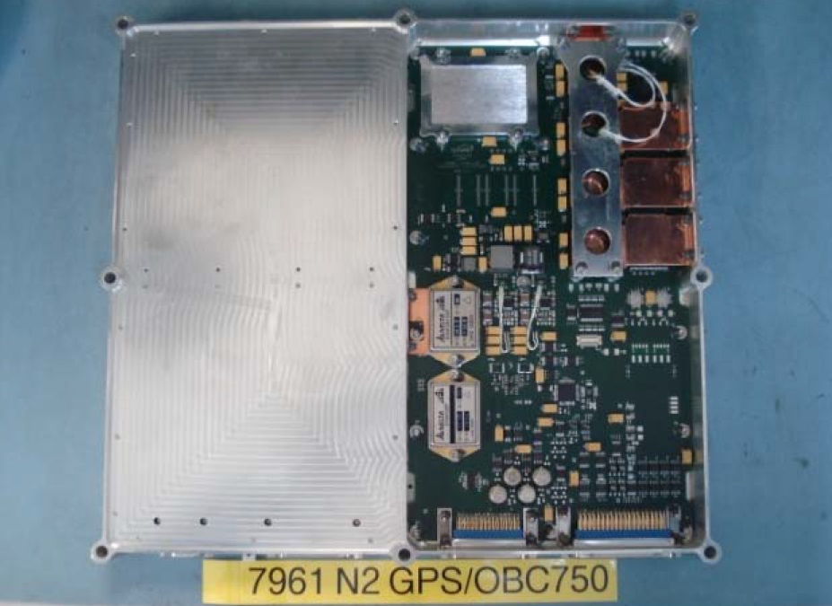
The OBC750 is built around a BM PPC750FL processor and tasked with receiving and processing commands from Earth and controlling all satellite subsystems.
The computer has a memory of 6MB EEPROM (boot software), 256MB EADS, 16MB MRAM and 16MB Flash. It supports the 1553B high-speed data bus as well as two dual CAN buses, eight LVDS inputs and outputs, four opto isolated inputs and four opto isolated outputs. The OBC measures 32 by 32 by 6 centimeters and weighs under 2.5 Kilograms requiring 20 Watts of power during operation and 3W in standby.
Internally, X50 employs a Controller Area Network (CAN) to transmit and receive data from CAN-equipped components while a dual-redundant Local Interconnect Network (LIN) communicates with the power system modules and distributed switches with a dedicated STRx card tasked with bridging telemetry and telecommands between CAN and LIN.
Two S-Band transceivers are employed for command uplink and data downlink with switchable downlink rates of 38.4 kbit/s in housekeeping mode and up to 4 Mbit/s when playing back science data and imagery.
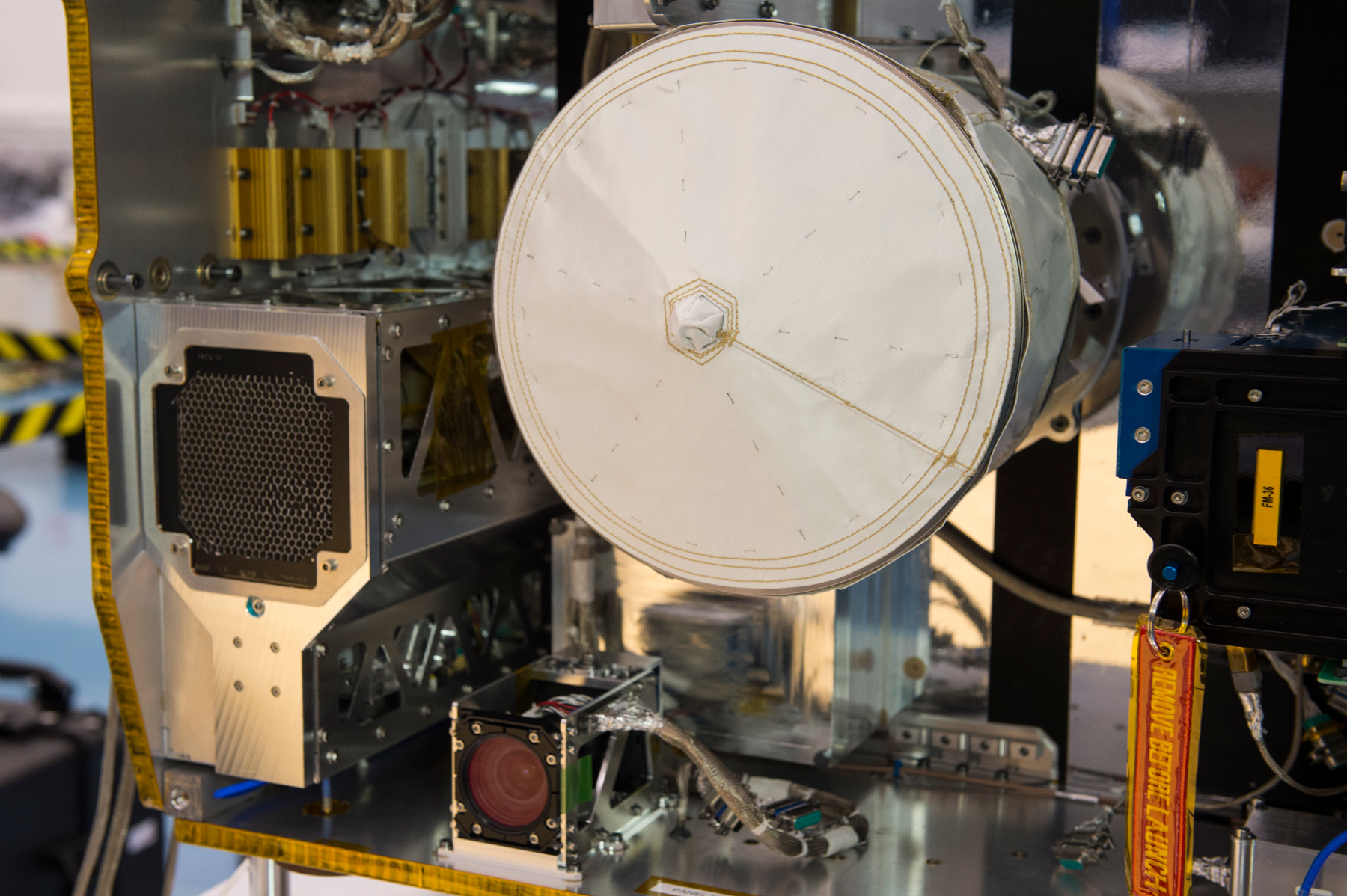
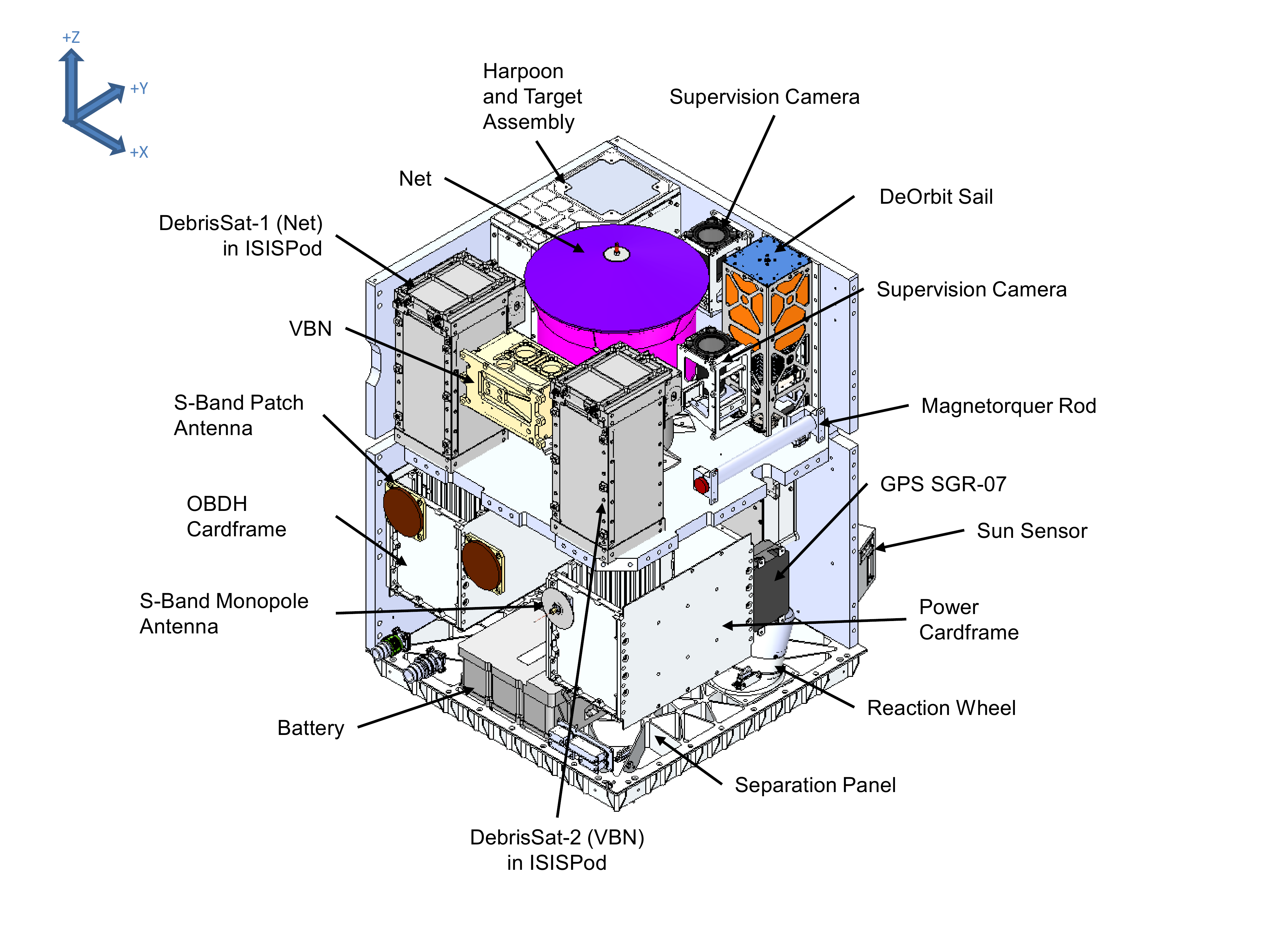
The RemoveDebris payload panel holds the following components: two ISIPod deployers holding DebrisSAT-1 and 2, a Net Deployment Mechanism, a Harpoon and Target Assembly, the VBN optical navigation sensors and electronics, the DeOrbit Sail Deployer, two Supervision Cameras and the S-Band and inter-satellite communications antennas.
Most of the payload elements are affixed to the side panels above the payload panel; the net is attached to the payload panel through a cylindrical tube to place it as close to the satellite’s center of gravity to avoid rotation torques as it is ejected. The Supervision cameras are mounted to provide the best possible views of what is occurring in front of the satellite (+Y).
DebrisSAT-1 (DS-1)
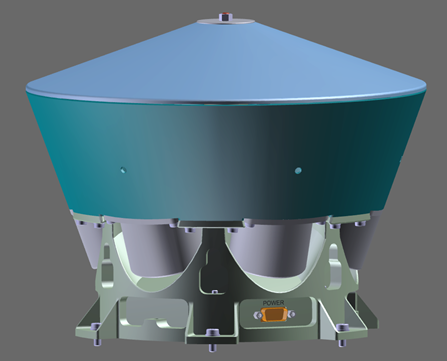
The DebrisSAT-1 CubeSat is 10 x 10 x 22.7 millimeters in size, compliant with the 2U CubeSat platform to enable a standard-size ISIPod deployment mechanism to be utilized. It comprises a 1U avionics section while the rest of its internal volume is used up by the inflatable structure. To simplify its design, DS-1 only relies on batteries and does not employ solar cells since its lifetime can be limited to only a few minutes, covering the release and initial flyaway, the deployment of the balloon and the transmission of data to the parent spacecraft.
The avionics stack comprises the battery module, a camera to film the main spacecraft as the CubeSat drifts away, and a burn wire assembly that holds the deployable structure in place. Deployment of the DS-1 structure is accomplished in a two-stage process beginning with cutting the burn wire to release torsion springs which deploy six booms intersecting with a central structural component which facilitates the Cold Gas Generator that inflates the booms and membrane. The balloon is stabilized with wires to enter the shape of an octahedron.
Separation from RemoveSAT is accomplished through loaded springs within the ISIPod deployer creating a relative separation rate of only 0.05 meters per second which gives DS-1 a two-minute window for the deployment of its balloon.
RemoveSAT will eject the Airbus-built net once DS-1 is at a distance of seven meters. Once the net makes contact, it will wrap around the balloon with end masses and motorized winches reel the neck of the net to secure the satellite within it. The Supervision Cameras will document the net deployment and the dynamics occurring when it makes contact with the target.
The intersatellite link between DS-1 and RemoveSAT is employed for the deployment trigger sent by the parent spacecraft and the transmission of imagery from the DS-1 camera to RemoveSAT.
DebrisSAT-2 (DS-2)

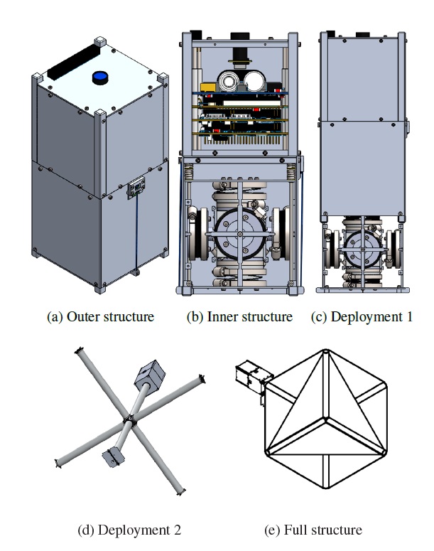
DebrisSAT-2, involved in the VBN navigation exercise, is more complex than its 2U CubeSat Companion, featuring a power-generation system and an active attitude control system. DS-2 shares the same 2-Unit structure of DS-1 but incorporates a larger avionics stack borrowed from the QB50 project developed by Surrey in cooperation with Electronic Systems Laboratory at Stellenbosch University.
The satellite will deploy four 1U panels from its sides to remove the CubeSat Symmetry and so enable the VBN payload to identify its attitude. Internally, the QB50 stack comprises three boards: the CubeComputer, CubeControl and the CubeSense Boards.
The cubeComputer is in charge of data processing via a 32-bit ARM Cortex-M3 processor, a Field Programmable Gate Array builds the primary interface with the various satellite systems and a MicroSD Card is available for data storage. CubeControl facilitates a magnetometer and magnetic torquer unit and interfaces with the sun and nadir sensors installed on the CubeSense board to calculate the craft’s orientation in space and command the torquers for attitude actuation. An additional board holds three reaction wheels to act as the primary attitude control device during the experiment; a dedicated GPS board provides position information relevant for putting the information collected by VBN into context.
The inter-satellite link with DS-2 will be used to relay telemetry and sensor data and to allow RemoveSAT to command the CubeSat into different orientations to collect data in different relative pointing modes. (Neither DS-1 nor DS-2 are equipped for space-to-ground communications.)
Deployers
Both DebrisSats are released by dispensers provided by ISIS – Innovative Solutions In Space based on the company’s standard deployment devices that have extensive flight heritage. However, the specific mission requirements of RemoveDebris resulted in a number of modifications needed on the deployment mechanisms.
In a typical launch vehicle mission, CubeSats are released within a handful hours of launch while Remove Debris will spend days if not weeks waiting for deployment from ISS followed by several days in free flight until the first CubeSat deployment event. One particularly important change was the integration of a power interface that allows the parent satellite to fully charge the CubeSat batteries prior to deployment and offering a data interface to the CubeSat computer to allow for a functional check before release.
The most significant alteration to the ISIPod deployers arises from the need of separating the two DebrisSATs at glacial speeds of 2 to 5 centimeters per second relative to the RemoveSAT parent to provide sufficient time for proximity operations. Typically, when launching on an upper stage, CubeSats are released at relative speeds of 1 to 2 meters per second.
Net Demonstration
Developed by Airbus Defence and Space, the Net Demonstration is a small-scale demo of a method for capturing uncooperative space debris that may not have the suitable external features for being captured with a robotic arm or a harpoon.
Within the framework of this demonstration mission, the starting conditions of the net capture are precisely controlled by placing a mock debris object (DebrisSAT-1) in a predictable position in front of the net release mechanism. Also, the demonstration will not actually capture the satellite by reeling in the net.
The basic working principle of the net relies on the fundamentals of physics: featuring end masses, the net will be released such that it expands to full size while traveling to its target and then wraps around it by means of the end masses which will wind the net closed while a motorized winch will tighten the neck area to prevent the net from unwinding again.
The Net Demonstration will be initiated upon ground command after DS-1’s batteries are fully charged. Separation of the satellite will occur at a speed of around 5 centimeters per second and the parent spacecraft will send a command via inter-satellite-link to initiate the deployment of the octahedral structure from the CubeSat to provide the target for the net. When DS-1 is at a distance of seven meters, around 140 seconds after deployment, RemoveSAT will deploy the net from the Net Capture Mechanism directed along the same axis as the CubeSat separation vector.
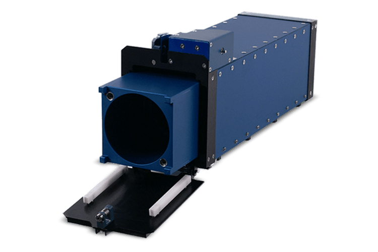
The Net Capture Mechanism is 27.5 centimeters in diameter and 22 centimeters tall, weighing 6.5 Kilograms. For a normal capture, the net would remain tethered to the parent spacecraft to reel in the captured debris, but RemoveDebris will release the net altogether to avoid two-body dynamic impacts.
The net chosen for this mission is a hemispherical spider-web type net with a fully expanded diameter of five meters using Kevlar for the net line material. It weighs around 600 grams and has a mesh size of 80 millimeters with a total of 196 meridian lines around the open edge of the net; less at the lid of the net. The winching mechanism connects the deployment masses with the lid and should provide a secure capture of the CubeSat and the inflated balloon, to be documented by the two Supervision Cameras along the +Y vector of the satellite.
Harpoon Test Assembly
The Harpoon payload comprises two components: the Harpoon Capture System that delivers the harpoon and the Harpoon Target Assembly that extends from the satellite body to provide the impact target for the harpoon. The deployable target was developed by Surrey Satellite Center after the original mission design with three CubeSats was changed. The Harpoon Capture System is a design of Airbus DS Stevenage, UK.
The Harpoon Capture System is designed to establish a hard point attachment and provide a link to the debris collection satellite via a flexible coupling, chosen to reduce risk to the active spacecraft by capturing the debris from a safe stand-off distance and keeping the debris at safe distance for towing.
The advantages of the harpoon-based system are seen in its low mass that could allow a debris satellite to fly with multiple harpoon systems, a low development and operational risk through a simple design, a fast delivery of the harpoon to capture objects spinning at fast rates, and an ability to perform characterization of the capture in ground-based tests.
The Harpoon Target Assembly consists of a coiled Carbon-Reinforced Polymer mono-stable boom contained in a closed compartment. When released, the boom will deploy by means of a motor to place the 10 by 10-centimeter target panel at a distance of 1.5 meters to the Harpoon Capture System, in view of the dual supervision cameras. When the experiment is complete, the target panel (with the harpoon in it) will be retracted to avoid interference with the Drag Sail later in the mission.
The Harpoon Capture System itself comprises three main elements: deployer, projectile and tether. The deployer imparts sufficient velocity to the projectile for penetration of the target structure, delivering it at a speed of over 20 meters per second which has been determined to be needed to reliably penetrate the typical aluminum honeycomb material used on modern-day satellites. The energy needed to send off the projectile is delivered by a one-use gas generator that directs high-pressure gas into a chamber to apply force against a piston which is held by a tear-pin until a force threshold is crossed. It then propels the projectile out of the deployer.
The projectile is designed to penetrate the 10 x 10 cm panel and deploy four barbs on the other side of the target, establishing the required locking interface that would enable pulling of a high-mass object. A shroud protects the barbs during penetration and allows the harpoon to successfully enter a structure at misalignments up to 45 degrees.
Vision Based Navigation
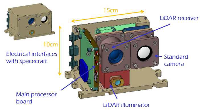
The Vision Based Navigation System VBN sets out to demonstrate a suite of sensors and onboard algorithms capable of providing rendezvous guidance with targets that have no provisions to assist with the rendezvous (non-cooperative targets). A number of previous missions carried such sensors in a shadow-mode while conducting orbital rendezvous maneuvers to collect real-world data feeding into the development of image processing and navigation algorithm techniques for non-cooperative rendezvous.
The VBN demonstration on the RemoveDebris Mission marks the next step to test out the equipment and algorithms in a scenario representative of an Active Debris Removal mission. Three objectives have been outlined for VBN: a) demonstrating state of the art image processing and navigation algorithms based on actual flight data, acquired through a standard camera and a flash imaging LIDAR, b) advancing the LIDAR to Technology Readiness Level 7 and c) demonstrating on-board processing of data to support real-time, autonomous navigation.

The VBN hardware installed on the payload deck of the RemoveSAT spacecraft combines a conventional 2D camera (passive imager) with a flash-imaging LIDAR (Light Detection and Ranging) developed by CSEM (Swiss Centre for Electronics and Microsystems). This combination will allow for ranging capability by measuring the phase difference of the two signals.
VBN will be active for the release of DebrisSAT-1 for the collection of 3D and 2D validation images. The main target for the VBN demo is DS-2 that will be monitored over a long duration to capture data over a range of distances, relative attitudes, lighting conditions and background properties, attempting to track the small satellite for as long as possible. Ground-truth data to compare the VBN measurements to will come through GPS measurements from RemoveSAT and DS-2 that transmits its GPS readings via the inter-satellite link.
All data collected during the VBN experiment will be processed on the ground through 2D/3D and 3D/3D matching as well as tuned navigation algorithms running through Extended Kalman Filters to fuse data from different sensors including the two visual cameras and attitude sensing information.
Supervision Cameras
RemoveSAT hosts two Supervision Cameras on its payload deck, one with a wide field of view of 65 by 54 degrees to capture the satellite separation events and the net demonstration and a narrow FOV camera to capture the harpoon demonstration across a 17 x 14° FOV. The two cameras employ a heritage design from the TechDemoSat-1 mission launched in 2014 and largely rely on Commercial Off The Shelf (COTS) technology that includes the CMOS sensor coupled to a standard machine vision lens.
Both cameras have been modified to withstand the launch and space environment and additional optimization with regard to their depth of field characteristics was made to meet the required performance for the demonstrations. The cameras collect 1280 x 1024-pixel imagery at a frame rate of ten frames per second.
Drag Sail
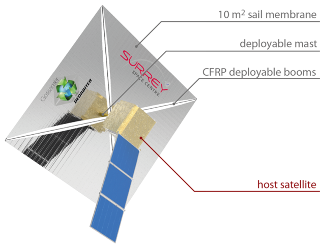
The Drag Sail hosted by RemoveDebris is a Surrey Satellite Center design using the typical arrangement of four triangular sail areas held in place by four booms deploying axially from the satellite body. It comprises two components: an inflatable mast deployer which moves the sail away from the platform and an extension mechanism that drives the four booms holding the sail membrane to their fully extended position to create a 10m² sail area.
A burnwire sets in motion the mast deployment by means of two gas generators which deliver the force needed to inflate the mast and position the sail around one meter from the satellite body. After this, the deployment motors are powered up to unfurl the carbon-fiber booms and drag sail. This process is again covered by the supervision cameras to provide information on the performance of the deployment system and potentially unforeseen dynamics within the sail.
Because of the sail size, communications and power generation may become limited. Particular focus during the deployment will be on the performance of the sail itself as well as possible attitude disturbances introduced during deployment. The efficiency of the drag sail will be assessed through GPS orbit determination data from the satellite as well as orbit tracking data coming from different sources.
