
Spacecraft Information
Soil Moisture Active/Passive
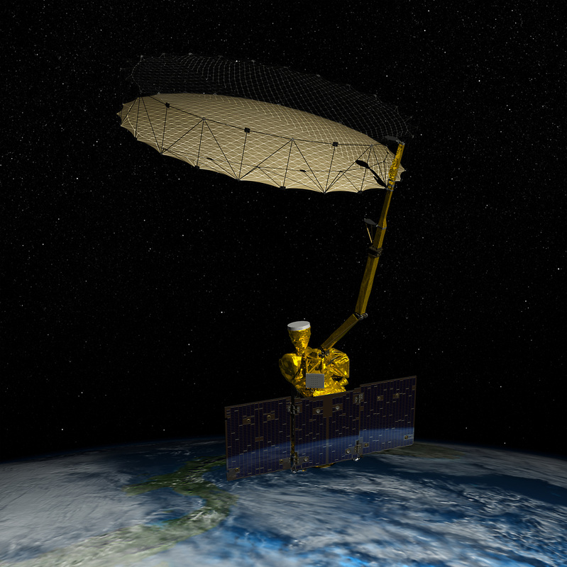
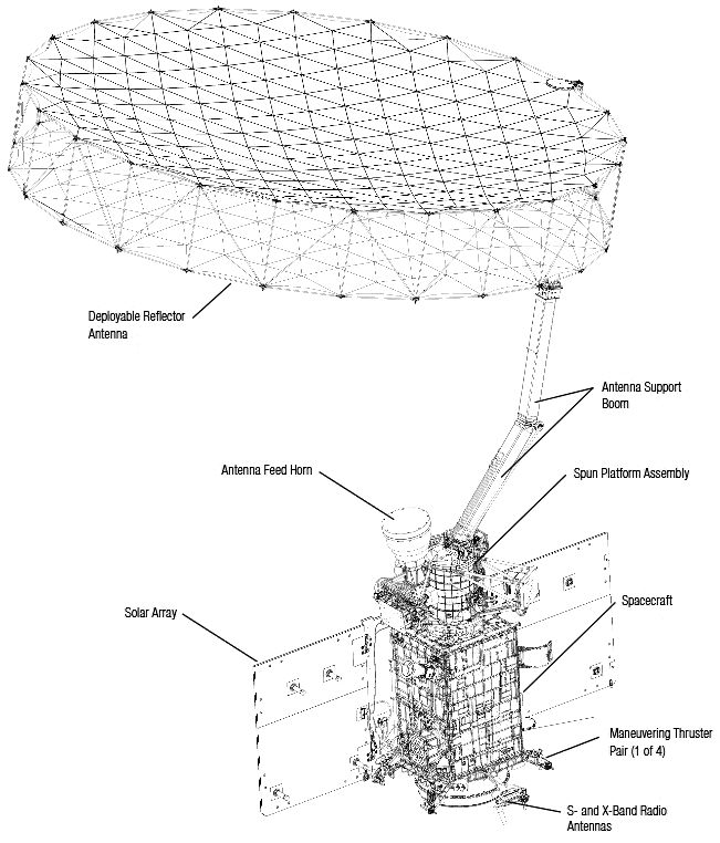
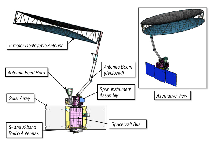
SMAP, standing for Soil Moisture Active/Passive, is a NASA Environmental Research Satellite that combines a radar and radiometric instrument to measure land surface and soil moisture on a global scale at a very quick revisit rate to deliver data valuable in the understanding of Earth’s water, energy and carbon cycles, as well as valuable information for the improvement of weather and climate forecasting, flood prediction and drought monitoring. Set for a three-year primary mission, the 944-Kilogram spacecraft will use a giant rotating reflector antenna to make its radar and radiometric measurements from a 685-Kilometer orbit.
The SMAP mission and spacecraft are being developed and operated at the Jet Propulsion Laboratory with assistance from NASA’s Goddard Spaceflight Center. Development of SMAP was initiated in 2007 as part of the Earth System Science Pathfinder Program after the National Research Council identified the mission as a high priority. NASA was able to put forward a heritage concept from the Hydros mission that was canceled for budgetary reasons in 2005. SMAP completed its concept review in 2008, allowing the in-depth development of spacecraft and instrument systems to begin.
By 2011, the instrument completed the Preliminary Design Review with the Critical Design Review of the entire spacecraft taking place in 2012, allowing hardware integration to begin ahead of a launch in 2015.
The SMAP spacecraft was specifically developed as a one-off design with a platform based on the requirements of its payload to reduce the overall complexity of the spacecraft and ensure proper accommodation of the instrument from a structural point of view but also looking at the resources that are required such as electrical power, thermal control and data storage and downlink capability which was one of the more important drivers in the design of the platform. Also, the spacecraft was designed to maintain compatibility with a number of launch vehicles and payload envelope sizes, allowing the selection of the launch vehicle to take place late in the mission design process.
SMAP is planned to operate from a sun-synchronous orbit at an altitude of 685 Kilometers at an inclination of 98 degrees – launched by a Delta II rocket. The local time of ascending node is 18:00. This orbit has an exact repeat cycle of 117 orbits (8 days), but due to the 1,000-Kilometer field of view of the instrument, SMAP achieves a repeat cycle of two days for high latitude locations (>45°) and three days for the equatorial regions.
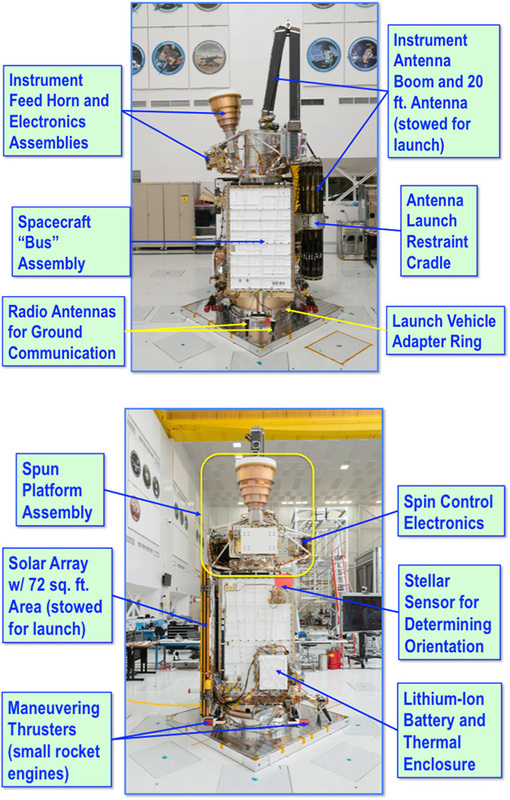
SMAP consists of a primary structure made of aluminum with a zenith deck that facilitates the Spun Instrument Assembly (SIA) and an anti-sun panel that builds the mounting surface for the radar system. The spacecraft bus itself is not spinning and consists of a pentagonal box structure that hosts external panels and an internal frame structure to provide mounting platforms for the various satellite systems.
External surfaces are used as radiators to dissipate excess heat into space. All structural components consist of aluminum and aluminum honeycomb materials. The subsystems are organized on the different external and internal panels so that they could be developed separately and integrated very easily.
The SMAP spacecraft has a total mass of 944 Kilograms and in its deployed configuration it measures 9.7 by 7.1 by 6.8 meters while in its stowed configuration it is 4.8 by 1.7 by 1.9 meters in size. The bus itself measures 1.5 by 0.9 by 0.9 meters.
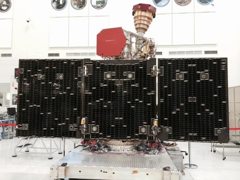
SMAP is equipped with a single solar array that is fixed in position and does not track the sun, requiring the spacecraft to point the array toward the sun for optimized power generation. The array is installed on one of the five larger side panels of the vehicle, consisting of one fixed and two fold-out panels connected to the central panel. The deployed solar array has a surface area of 7.8 square meters allowing the gallium-arsenide solar cells to generate a total power between 1,400 and 1,500 Watts. Dedicated regulators and control units are in charge of controlling the state of charge of the spacecraft batteries and distributing power to the various subsystems of the satellite using a 31-volt main power bus. SMAP is equipped with Lithium-ion batteries – a main battery with a 50 Amp-hour capacity and three auxiliary batteries with a total capacity of 28Amp-hours that reside within the launch vehicle adapter to deliver power during the ascent phase.
Thermal control on the SMAP satellite uses a combination of passive and active systems. Multilayer insulation is used on the various satellite systems and survival heaters are installed on various components to ensure critical systems can maintain an operational temperature at all times. Heat from the electronics is rejected through external radiator panels. The battery pack is equipped with its own radiator, MLI and heater system since the efficiency of power storage strongly depends on the temperature the battery is kept at.
SMAP employs an Attitude Determination and Control System that is based on previous heritage from a variety of missions, using a series of different sensors and actuators. Attitude determination is accomplished by a star tracker unit, sun sensors and inertial measurement units. The main sources of attitude information are the two star trackers of the spacecraft that are installed on a side panel of the vehicle, pointing to the zenith direction to be able to acquire images of the star-filled sky in a 10 by 10-degree field of view. Optical imagery acquired by the star tracker is analyzed by an algorithm that searches a catalog of thousands of bright star constellations to be able to precisely calculate the three-axis orientation in space.
The Inertial Measurement System comes into play during re-acquisition of the spacecraft when attitude rates have to be reduced below the acquisition rate of the star trackers that can only track stars at low body rates. The system is also used to propagate attitude knowledge determined by the star trackers through gaps in stellar attitude updates. SMAP uses a redundant set of two Miniature Inertial Measurement Units manufactured by Honeywell. The Inertial Measurement Unit has extensive flight heritage and features a robust design using the GG1320 Ring Laser Gyro that provides precise rotation measurements.
The system uses the basic principle that counter-propagating laser beams have different frequencies with the difference dependent on rotation rate which can be measured to calculate the rotation rate about the RLG’s sensitive axis. The MIMU weighs 4.5 Kilograms being 23 by 17 centimeters in size. It has an operational measurement range of +/-375°/sec at a low bias of under 0.005°/hour. The system can tolerate the radiation conditions in Low Earth Orbit and handles accelerations of up to 25G.
SMAP features 12 Sun Sensors installed on the various external panels of the spacecraft including the solar array. Data from all sensors is collected to calculate the direction of the solar vector with sufficient accuracy to keep the array pointed to the sun to ensure sufficient power generation in the event of a spacecraft safe mode. The Sun Sensors are also used for re-acquisition of the star trackers.
Attitude actuation is provided by a Reaction Wheel Assembly and Magnetic Torque Rods. SMAP is equipped with three reaction wheels to provide three-axis pointing plus a fourth wheel that is used for momentum compensation to maintain a momentum balance between the spacecraft and Spun Instrument Assembly, counteracting any disturbance torques. The reaction wheel assembly is a rotating inertial mass that is driven by a brushless DC motor that spins the wheel. When accelerating the wheel, the satellite body to which the wheels are directly attached will rotate to the opposite direction as a result of the introduced counter torque.
Three Magnetic Torque Rods with redundant coils are used to create angular momentum by running a current through coils in the presence of Earth’s magnetic field. The torquers are regulated by computers that control the current that is passing through the coils in order to control the force generated on each axis. The magnetic torquers are used during momentum dumps and for attitude control in spacecraft safe mode. Actuation of the torquers is commanded based on readings from a three-axis magnetometer.
Orbit determination and position data is gained through two-way Doppler measurements performed several times a day. Position data is calculated onboard the spacecraft through propagation of Doppler measurements. GPS receivers were no option for the SMAP mission due to the blockage of a field of view to any GPS satellites caused by the large antenna atop the zenith panel of the satellite.
SMAP uses a monopropellant propulsion system developed at JPL employing components with extensive heritage. A spherical titanium, diaphragm propellant tank manufactured by ATK holds 81 Kilograms of Hydrazine at launch, pressurized pre-launch and operated in blowdown mode throughout the mission. The propulsion system consists of eight 4.5-Newton thrusters that were also in use aboard the Cruise Stages of the MER and MSL Mars Rovers. The thrusters use redundant latch valves and pressure sensors to provide built-in redundancy.
To generate thrust, the system makes use of the catalytic decomposition of Hydrazine over a metallic catalyst bed. SMAP can use its propulsion system for orbit maintenance and corrections, attitude control and reaction wheel desaturations. The mission has a total delta-v budget of 112 m/s which is sufficient to maintain an operational orbit well beyond the design life of the spacecraft.
The SMAP spacecraft uses an onboard Command and Data Handling Subsystem that builds on a number of previous JPL spacecraft to take advantage of lessons learned and minimize risk since SMAP uses a one-string architecture given the budget, mass requirements and planned duration of the mission.
The brain of the SMAP spacecraft is a RAD750 flight computer that has flown to space on several missions including Mars rovers and Earth observation satellites. RAD-750 is a single-card computer manufactured by BAE Systems in Manassas, Va. The processor can endure radiation doses that are a million times more extreme than what is considered fatal to humans. The RAD750 CPU itself can tolerate 200,000 to 1,000,000 rads. Also, RAD750 will not suffer more than one event requiring interventions from Earth over a 15-year period.
“The RAD750 card is designed to accommodate all those single event effects and survive them. The ultimate goal is one upset is allowed in 15 years. An upset means an intervention from Earth — one ‘blue screen of death’ in 15 years. We typically have contracts that (specify) that,” said Vic Scuderi BAE Business Manager.
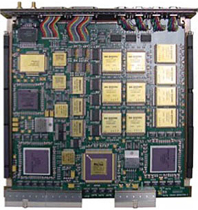
RAD-750 was released in 2001 and made its first launch in 2005 aboard the Deep Impact Spacecraft. The CPU has 10.4 million transistors. The RAD750 processors operate at up to 200 megahertz, processing at 400 MIPS. The CPU has an L1 cache memory of 2 x 32KB (instruction + data) – to improve performance, multiple 1MB L2 cache modules can be implemented depending on mission requirements.
RAD750 operates at temperatures of -55°C to 125°C with a power consumption of 10 Watts. The standard RAD750 system can tolerate 100,000rads. SMAP uses the VxWorks operating system also found in many other missions including the Mars Exploration Rovers and the Mars Science Laboratory. Some elements of the operating software were developed specifically for SMAP, but teams were able to use a number of elements used in previous missions.
The internal data system of SMAP uses PCI connections for the Command and Data Handling System while the backbone of the data system of platform and core is a 1553 data bus supporting the exchange of commands and housekeeping telemetry between the onboard computer and all subsystems including the attitude control system, power system and pyrotechnics control unit. An analog RS-422 bus is used for commanding of the radar and radiometer electronic control units. High-data rate communications between the instrument and the data systems are accomplished using a LVDS connection. Payload data is stored in a 128GB non-volatile memory.
SMAP employs a redundant S-Band communications terminal for command uplink and telemetry downlink via NASA’s Earth Network and Space Network. The Tracking and Data Relay Satellite system can also be used for data exchange with the SMAP spacecraft if needed. Two redundant X-Band transmitters are used to deliver payload data to ground stations. The transmitters are facilitated on a fixed outrigger on the nadir (Earth-facing) panel of the spacecraft. S-Band communications reach data speeds of up to 512kbit/s while the high-speed X-Band link operates at 130Mbit/s.
The S-band system includes a set of redundant 5-Watt transponders, a single S-band low-gain antenna and a coaxial switch to select the active transponder. The X-band telecomm system is comprised of redundant 8-Watt transmitters, a single low-gain antenna and a bandpass filter as well as switching electronics.
The SMAP spacecraft has been designed using a single-string approach with redundancy in select systems such as the attitude determination and control, propulsion, and communication systems. Fault protection modes have been divided into two groups for SMAP – the majority of faults will result in a spacecraft standby mode in which the SIA is not de-spun. Only the most severe faults will lead to a Primary Safe Mode or Emergency Safe Mode requiring the SIA to be de-spun to place the spacecraft in a safe state. Whenever SIA is de-spun, the attitude control system has to cope with resulting torques and the re-initiation of science operations at the end of a safe mode is a time-consuming process that would lead to a gap in science data.