
GSAT-6A Satellite Overview

GSAT-6A is an advanced S-Band communications satellite built by the Indian Space Research Organization for operation under INSAT’s communications satellite fleet, primarily for use by the government and military while also serving as a technology testbed for mobile communications and improved network management techniques. Built on ISRO’s I-2K platform, GSAT-6A is a close copy of the GSAT-6 satellite launched in 2015 and delivers a combination of wide-beam C-Band and high-capacity S-Band spot beam coverage.
GSAT-6 was launched by the GSLV Mk.II D5 mission in 2015 as India’s second satellite for strategic communications, following up on the Navy’s GSAT-7 communications satellite orbited in 2013. The GSAT-6 mission introduced a number of new elements including a large deployable S-Band antenna reflector and the interconnection of S- and C-Band up/downlinks to deliver mobile coverage as well as high-capacity backhaul for larger terminals and gateway beams.
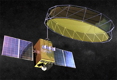
GSAT-6A is a near carbon copy of the GSAT-6 satellite to increase S-Band capacity and ensure continuation of services into the second half of the 2020s. Weighing in at 2,140 Kilograms, GSAT-6A utilizes ISRO’s I-2K platform, a six-meter Unfurlable Antenna Reflector for S-Band up and downlink and an 0.8-meter deployable C-Band reflector to carry the wide-beam up/downlink. S-Band is employed to connect mobile terminals to the GSAT-6A satellite while the C-Band system carries the up/downlink between the satellite and its hub stations in India.
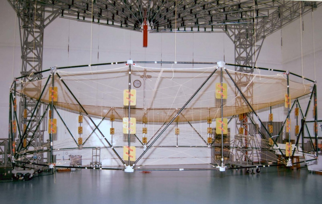
The six-meter S-Band antenna is the largest in-space deployable launched by ISRO to date, employing a lightweight structure of a perimeter truss segment which can fold-out like a camping chair and offers stability through a series of cross-beams between the two perimeter tiers that hold in place the metal mesh serving as reflective area and supported in a parabolic shape. The S-Band system generates five spot beams over the Indian main land employing the frequency reuse scheme to increase the efficiency of the spectrum utilization.
The communications payload of the satellite consists of five 9 MHz C x S-Band transponders generating five S-Band spot beams for downlink while the uplink is carried via C-Band from a hub station in India. Five S x C-Band transponders, each with a bandwidth of 2.7 MHz, receive their uplink in S-Band from mobile user terminals and downlink their communications to ground stations in C-Band. The satellite’s Telemetry & Telecommand system uses a C-Band solution from heritage ISRO programs.
The exact purpose of the GSAT-6A satellite has not been made clear by ISRO, though media reports the satellite will be dedicated to government and strategic communications. ISRO said about the mission: “The satellite will also provide a platform for developing technologies such as demonstration of 6 m S-Band Unfurlable Antenna, handheld ground terminals and network management techniques that could be useful in satellite based mobile communication applications.”
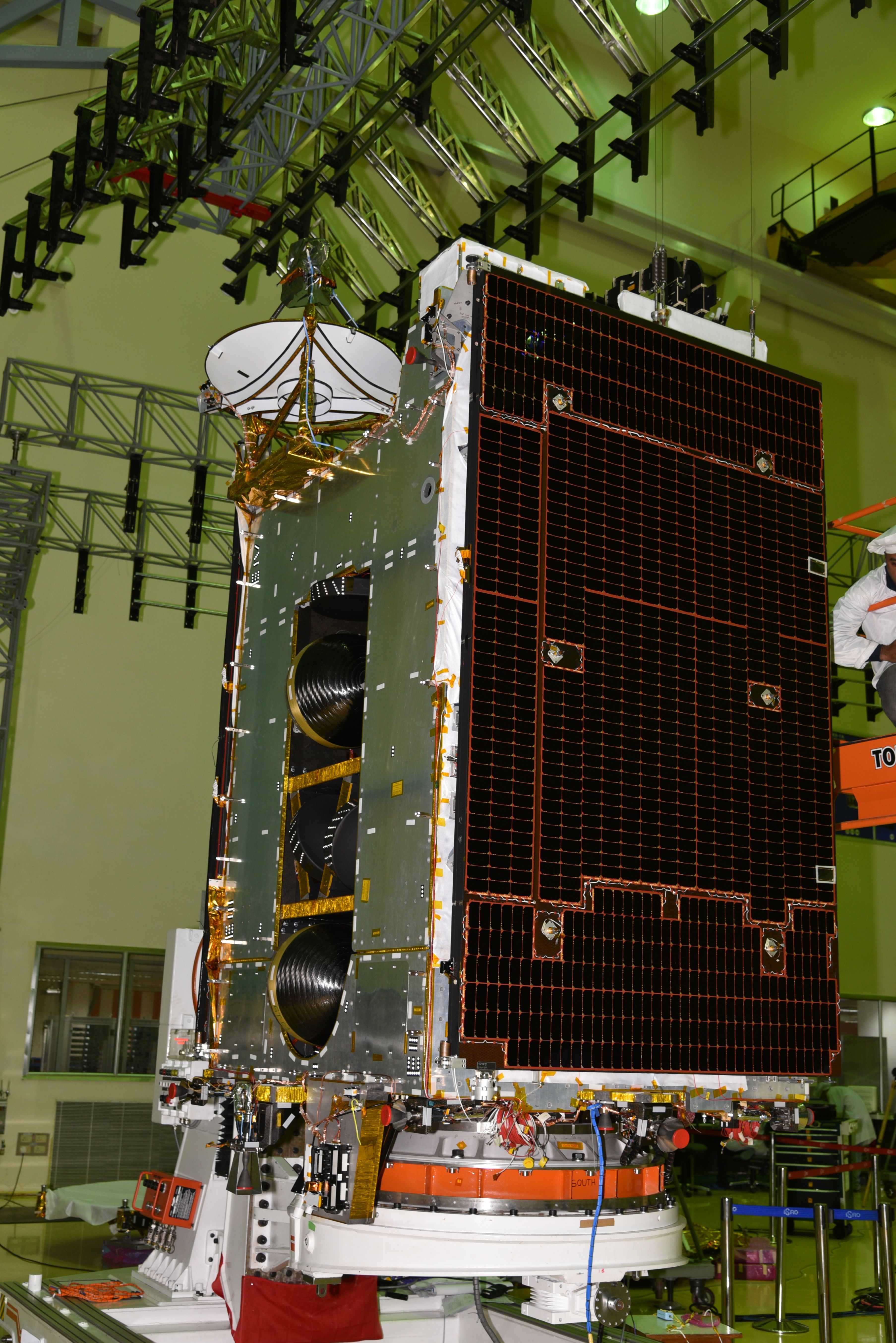
The satellite measures 2.1 x 2.5 x 4.1 meters in size when in its launch configuration, expanding into an envelope of 9.4 x 9.6 x 6.1 meters when deploying its two-power generating solar arrays and the antenna reflectors. Its two solar arrays, each comprising two hinged panels and a solar tracking mechanism, deliver an end-of-life power of 3,150 Watts via Ultra-Triple Junction Ga-As solar cells, feeding power to 16-cell Li-Ion batteries with a capacity of 100 Amp-hours. The upgraded power architecture of the GSAT-6 series employs a 40-Volt power bus for the platform systems based on GSAT heritage and a new 70-Volt architecture serves the payload via a regulated power bus.
GSAT-6A employs a Unified Bipropellant System comprising two large propellant tanks, manifold systems delivering storable propellants to the thrusters and a propulsion system built around the 440-Newton Liquid Apogee Motor used as main engine and 16 attitude control thrusters for three-axis stabilization during maneuvers and orbital fine tuning/stationkeeping. The total propellant mass carried by the satellite at liftoff is approximately 1,135 Kilograms.
The standard propulsion package used by a number of ISRO satellite projects uses the trusted Liquid Apogee Motor for apogee-raising maneuvers while eight 22- and eight 10-Newton thrusters are used for attitude maneuvers and stationkeeping in Geostationary Orbit. All three engine types use hypergolic propellants, MON-3 oxidizer (Nitrogen Tetroxide with 3% Nitric Oxide) and Unsymmetrical Dimethylhydrazine as fuel. Tank pressurization is accomplished by using high-pressure Helium.
LAM provides 440 Newtons of thrust which equates to 44.87 Kilograms. The engine operates at a mixture ratio (O/F) of 1.65 and has a nozzle ratio of 160 providing a specific impulse of 315 sec. The engine’s injector is a co-axial swirl element made of titanium while the thrust chamber is constructed of Columbium alloy that is radiatively cooled. Electron welding technique is used to mate the injector to the combustion chamber.
LAM is a robust engine that can tolerate injection pressures of 0.9 to 2.0 MPa, propellant temperatures of 0 to 65°C, mixture ratios of 1.2 to 2.0 and bus voltages of 28 to 42 Volts. The engine is certified for long firings of up to 3,000 seconds and a cumulative firing time of >23,542 seconds.
The 22N thrusters also use co-axial swirl type Titanium alloy injector and a Columbium combustion chamber. The thrusters operate in blowdown mode at a chamber pressure of 0.68 Mpa creating a specific impulse of 285sec. The 22N thrusters have an area ratio of 100. It can be operated in pulse mode with a minimum pulse duration of 8 milliseconds that supplies a minimum impulse of 65mN*sec. Each 22N thruster assembly weighs 0.8 Kilograms.
The 22N thruster is qualified for 300,000 duty cycles as it is mostly operated in pulse mode, but it can also withstand a single burn of up to 10,000 seconds and a cumulative burn time of 70,000 seconds. The engine tolerates a variety of operating conditions: 0.9 to 1.9 MPa on injection pressure, 0.2 to 2.0 on mixture ratio, -5 to 65°C on prop temperature and 28 to 42 Volts on bus voltage.
ISRO’s 10N bi-propellant thrusters are similar to the 22N units and leverage a number of lessons learned from their development. They use similar swirl type injectors which create an unintentional but welcome film cooling in an otherwise radiatively cooled engine design. The combustion chamber and nozzle are manufactured from Columbium alloy and the thrusters have an area ratio of 200. The 10N thrusters deliver a 285sec and achieve a minimum impulse bit of 30mNs.
