
CREAM – Cosmic Ray Energetics and Mass
CREAM – the Cosmic Ray Energetics and Mass Instrument – is an energetic particle detector taking up residence outside the International Space Station to directly sample ultra-high-energy particles from outside the Solar System that exceed the energies achievable with any current-generation particle accelerator on Earth and hold clues on the composition of the universe.
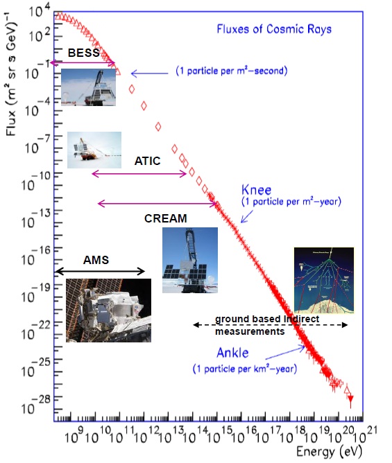
The CREAM experiment is hoped to answer the century-old question on what gives cosmic energies such tremendous energies (1,000 Tera-Electronvolt +) and how does that affect the composition of the universe. CREAM can measure particles at higher energies than the Space Station’s high-profile astro-physics payload, the Alpha Magnetic Spectrometer 2, and is therefore hoped to reveal what causes a ‘knee’ or decline in the cosmic energy spectrum around a thousand trillion electron-volts where particle theory would not predict such a decrease.
CREAM is hoped to answer a number of questions in addition to addressing the spectral knee, probing the origin of cosmic rays and identifying the contribution of supernovae to the cosmic ray spectrum, looking into the past to assess the history of the cosmic particle distribution in the Milky Way galaxy and looking at single or combinations of mechanisms that could be an explanation for the cosmic ray spectrum.
The overall goal of the CREAM experiment is stated as ‘extending the energy reach of direct measurements of cosmic rays to the highest energy possible to investigate cosmic ray origins, acceleration and propagation.’ The collection of such measurements is inherently difficult given the low flux of particles with ultra-high energies (meaning particles of energies of interest are few and far in between, requiring either large detectors or long exposures to collect statistically relevant data).
Put in numbers, CREAM’s goal is to measure the spectrum of cosmic rays between 1010 and 1015 electron-volt for each species from Z=1 (Hydrogen) to Z=26 (Iron). This will be accomplished by a combination of detector elements providing measurement of particle charge, energy and discriminating between hadrons and electrons to tackle additional science goals by measuring the cosmic ray electron spectrum up to 100 Giga-electronvolt.

Research into the high-energy mechanisms of the universe has made incredible progress over the past century, from high-altitude balloon missions with basic sensors to state-of-the-art particle detectors being deployed to space – including several on the International Space Station. However, even with ever increasing energy ranges, instruments used to date could not deliver the definitive answers that have so long been sought after by scientists across the globe. CREAM involves scientists from the United States, Republic of Korea, Mexico and France
The CREAM instrument package has amassed 161 days of data collection above the atmosphere by means of six high-altitude balloon flights (2004-2010) around the South Pole where Earth’s magnetic field lines are essentially vertical and permit a direct measurement of incoming cosmic rays. ISS offers an ideal environment for a long-duration exposure to gain data on the low flux area of high-energy cosmic rays – requiring the airborne CREAM system to be re-packaged to comply with the payload accommodations of the Kibo laboratory’s Exposed Facility, also known as the Space Station’s porch.
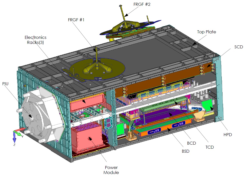
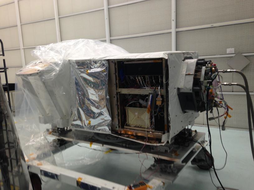
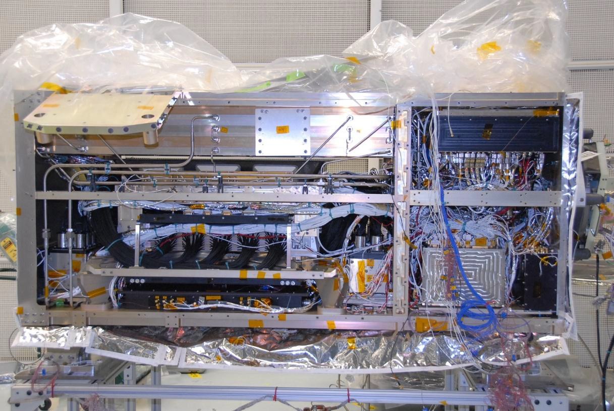
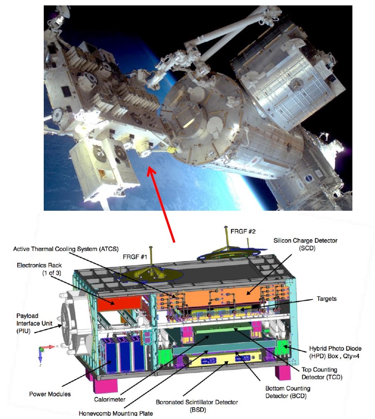
The CREAM-ISS payload weighs in at 1,258 Kilograms and measures 1.85 by 0.5 by 1.0 meters in size; the original cream required an envelope of 1.8 by 1.8 meters. CREAM combines several different detector layers to collect its high-quality, high-energy measurements: a four-layer Silicon Charge Detector for precise charge measurements, Carbon Layers to induce hadronic interactions, a Tungsten Calorimeter to determine particle energy and direction, a Boronated Scintillator for electron-proton separation & neutron collection, and Top/Bottom Counting Detectors.
The CREAM-ISS configuration retains the Silicon Charge Detector for charge measurement, the main Calorimeter and the Carbon Targets are also being retained from the balloon-borne CREAM instrument and the Top/Bottom Counting Detectors and Boronated Scintillator Detector are being added for electron separation, and as redundant energy trigger for the Calorimeter.
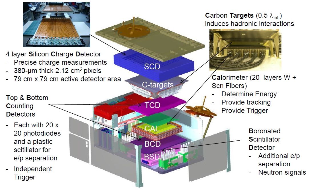

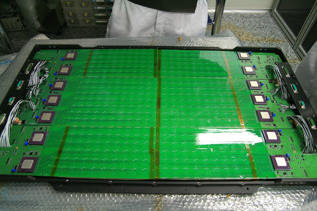
Incoming cosmic rays first strike the Silicon Charge Detector (SCD) that represents a finely-segmented (pixelated) multi-layer detector for the precise measurement of the charge of incident particles. SCD comprises four layers with 380-micrometer thick 2.12 cm² pixels, creating an effective detector area of 81.8 x 81.8 centimeters. Together with analog & digital electronics and its mechanical structure, SCD weighs 143 Kilograms and has outer dimensions of 81.8 by 81.8 by 16.6 centimeters, located above all other CREAM detectors.
Each layer hosts 2688 pixel sensors and therefore the SCD has a total of 10,752 channels. The detectors are silicon PIN diodes fabricated on 525 µm thick silicon wafers with 16 pixels on each sensor element which itself is attached to a flexible printed circuit board for signal readout. Seven silicon sensor elements are mounted on the front side of an analog board to form a ladder with overlap between ladders to create a system with zero dead area. The ‘ladder’ is the basic unit that populates the SCD, all ladders are individually powered and monitored via their current, voltage and temperature sensors.
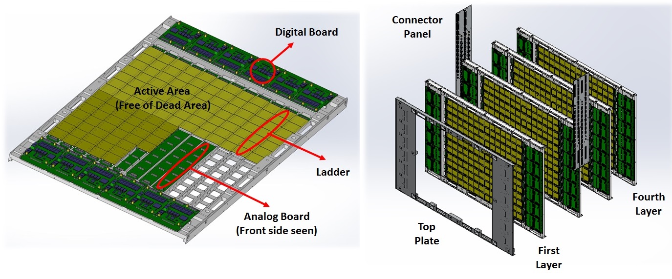

SCD employs an analog read out chain based on Application Specific Integrated Circuit technology with each ladder’s ASIC board accepting the charge signals from the silicon sensors and converting them to a voltage pulse. The instrument’s digital electronics comprise voltage regulators, Field Programmable Gate Array Chips and Analog-to-Digital converters. Each digital board serves two ladders and configures and controls the analog boards of the ladders while also carrying out digitization of the voltage signals for the two ladders for transmission to the main instrument electronics. (In total, each SCD layer hosts 2688 pixels on 168 sensor elements on 24 ladders with 24 analog boards and 12 digital boards.)
After passing through the SCD that delivers a precise charge measurement, incoming particles pass through a layer of 0.5 λint thick graphite targets (half the nuclear interaction length) to induce hadronic interactions in order to create showers that can be detected by subsequent detectors.
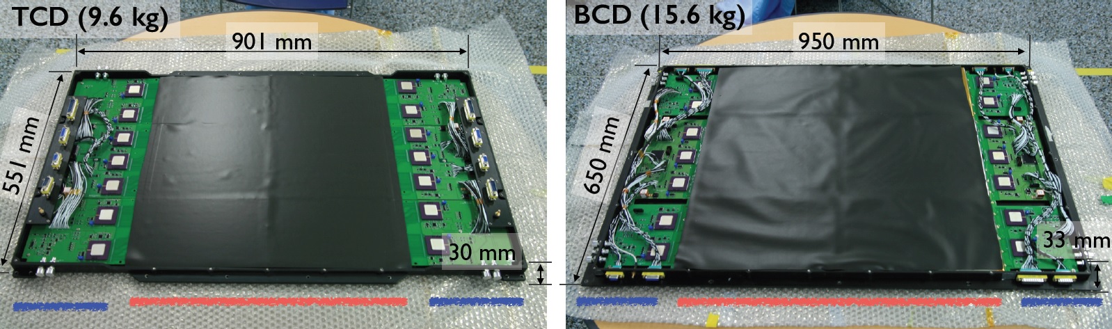
Residing below the Carbon Targets is the Top Element of the Top & Bottom Counting Detectors (TCD/BCD) with the BCD element located under the Calorimeter. These paired detectors are designed for separating electrons from protons by their different lateral and longitudinal shower shapes in the 300 to 800 Giga-elecronvolt energy range. TCD/BCD also provide a redundant trigger for the calorimeter and a low-energy electron trigger.
Separation of electrons and protons is paramount when attempting to look into high-energy electron physics which is part of CREAM’s science goals – a task complicated by the fact that energetic protons have a much higher abundance than electrons at similar energies and misidentification of candidate electrons can significantly distort experiment results.

However, conclusive electron spectrum measurements up to 100 GeV are highly desired by the scientific community as cosmic ray electrons are known to lose energy fairly quickly through synchroton radiation in galactic magnetic fields and reverse Compton scattering on the cosmic microwave background. A conclusive measurement of an excess of high-energy electrons would be of interest as it would suggest a local source close to Earth.
The TCD is 90.1 x 55.1 x 3.0 centimeters in size and weighs 9.6 kg while the BCD is slightly larger at 95.0 x 65.0 x 3.3 centimeters, weighing 15.6 Kilograms. Each of the detectors holds an EJ-200 Plastic Scintillator and a 20 x 20 silicon photodiode array (400 diodes). TCD has an active area of 50 x 50 centimeters while BCD has a larger active area of 60 x 60 cm.
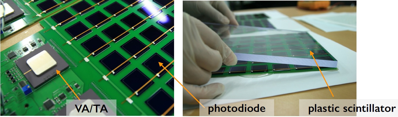

Scintillator crystals have the ability of absorbing energetic particles and re-emitting their energy in visible radiation which can be detected with a photomultiplier tube that converts the visible photons into electrons through the photoelectric effect and measures the current generated by the electrons using detector electrodes.
TCD/BCD employ optical silicone adhesive to bind the scintillator with the photodetectors and an enhanced specular reflector wraps around the scintillator to prevent any light loss. The photodiodes are 2.3 x 2.3 cm in size, 650 µm thick, use n-type silicon wafers and have an active area of 2.0 x 2.0 cm; they have a 75% quantum efficiency in the 400 to 450 nanometer wavelength range of the scintillator.
The TCD/BCD electronics system comprises two mother boards and four daughter boards with three analog boards, one ACTEL chip and two DC converters on each motherboard and two VA-TA read-out chips on the daughter boards to receive the photodiode signals that are to be amplified and digitized. The VA front end elements each have 32 channels and have a charge sensitive amplifier, a slow shaper and a sample-and-hole circuit while the TA elements also have 32 channels with low-power fast-triggering ASIC chips, fast shapers and discriminators in each channel. A 16-bit Analog-to-Digital Converter produces the data output from TCD/BCD for transmission to the main data handling chain.
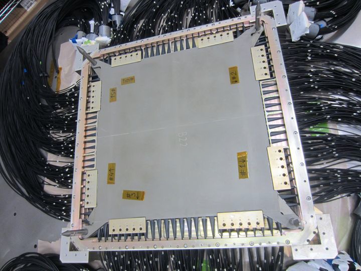
The Calorimeter is the heart of the CREAM instrument – a tungsten-scintillator sampling calorimeter providing the primary energy measurement for incoming particles, tracking particle directions, and triggering the other sensing components. Imaging Calorimeters are characterized by a finely granulated readout with a high degree of segmentation featuring a large number of readout channels as opposed to conventional calorimeters consisting of large crystals connected to a single read-out channel. This allows for a detailed measurement of particle identity, travel direction and energy as well as the creation of Particle Flow Algorithms. Imaging Calorimeters have a sandwiched design, alternating between active detector elements and passive absorber elements.
The CREAM Calorimeter employs 20 alternating tungsten and scintillating fiber ribbon layers with the tungsten plates acting as absorbers and the scintillators providing a directional measurement of a particle’s path as well as its energy which is measured as a function of penetration depth. Each tungsten plate is 50 by 50 centimeters in size and 0.35 cm in thickness; the scintillating layer comprises fifty one-centimeter wide and nineteen 0.05 cm BCF-12MC scintillating fibers. The ribbons are laid out along X and Y directions alternatively to allow 3D particle directions to be reconstructed.
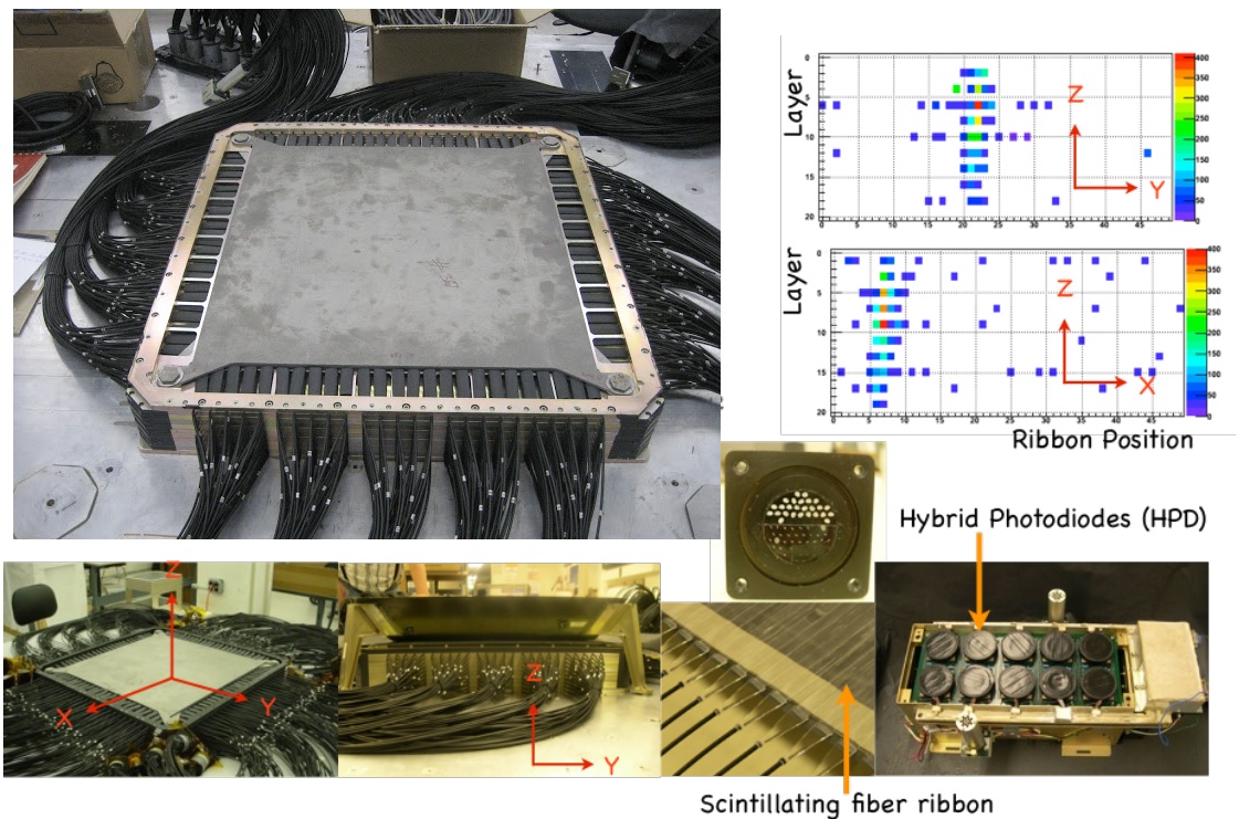
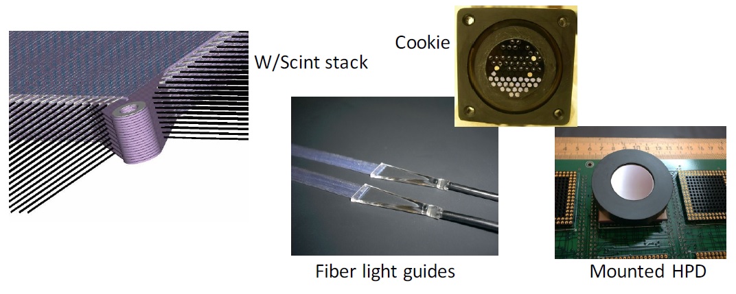

Each of the scintillator fiber ribbons is connected to a light guide and a clear fiber transports the optical signal to a Hybrid Photo Diode (HPD) array where the optical signals are converted to electrons using the photoelectric effect. The linear 1:100,000 HPDs are coupled to Readout Electronics based on application-specific integrated circuits that digitize the signals from each fiber with precise time-stamps for event logging. The arrangement of active elements within the system has been chosen to provide the precision necessary to separate incident particles from backscattered particles, precisely determine the starting point of the shower and determine the incident particle trajectory.
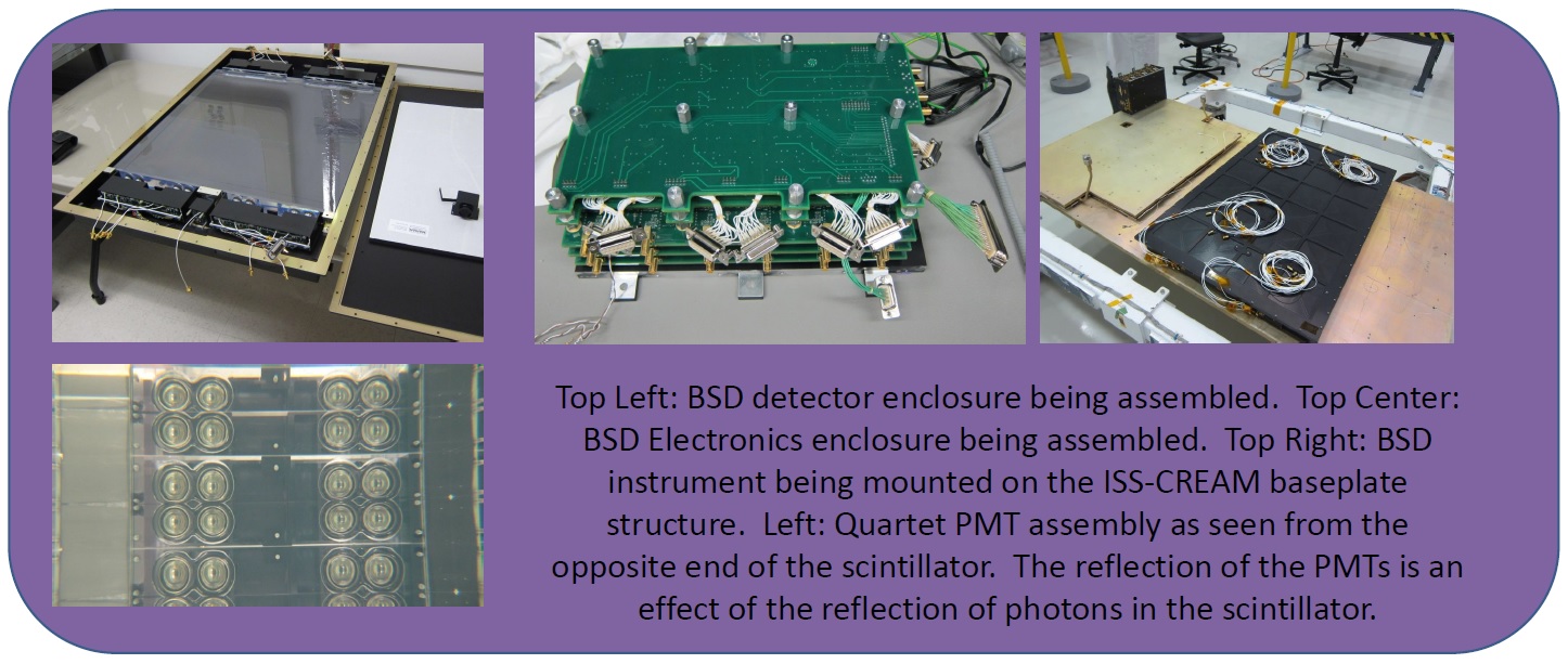
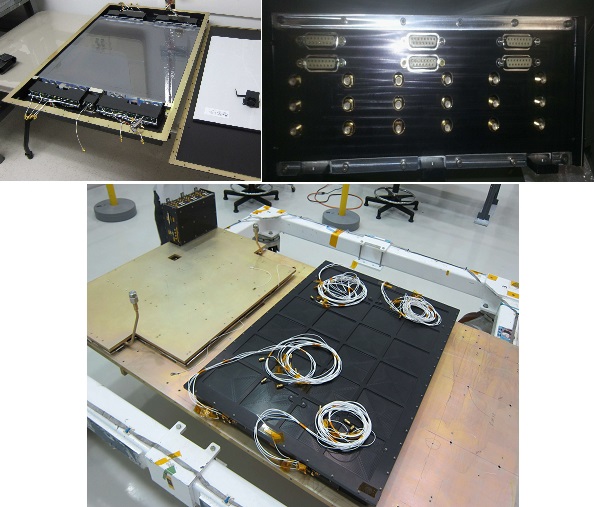
Sitting underneath the Calorimeter and Bottom Counting Detector is the Boronated Scintillator Detector (BSD) to detect late thermal neutron shower activity which can be used as a further method for separating electrons and hadrons as hadron-induced showers tend to be accompanied by significantly more neutron activity than electromagnetic showers (the difference being one order of magnitude which is easily differentiated within a neutron detector). BSD consists of a boron-loaded plastic scintillator (5% boron concentration by mass) coupled to 18 photo-multiplier tubes. With BSD, electron and proton separation provided by the Top & Bottom Counting Detectors can be enhanced significantly to improve the overall hadronic rejection and deliver higher confidence in the electron spectra generated by CREAM.
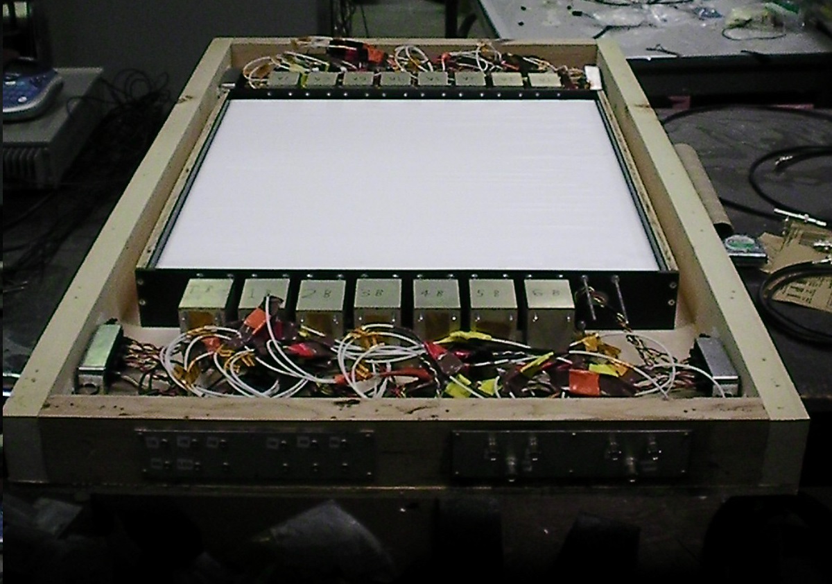
The 60 x 60 x 3.8-centimeter boron-loaded scintillator can be excited by incoming neutrals, yielding alpha particles, 7Li and gamma-rays. The latter are converted to visible light pulses in the plastic scintillator material with some 570 photons created by every neutron capture which can be detected by the Photomultipliers coupled to a sensitive detector. The neutral activity occurs around 400 nanoseconds after the initial calorimeter shower is detected.
BSD’s scintillator block is wrapped in ultra-reflective PTFE and enclosed in a light-tight box to prevent any light loss or intrusion of outside light sources. The instrument’s photodiode detectors are sensitive for wavelengths between 300 and 650 nm, providing a good match for the 425 nm maximum emission wavelength of the EJ-254 scintillator material.
One challenge for the BSD instrument is avoiding photoelectron signals from the early calorimeter shower which are similar in amplitude to the late shower signals that are of interest for e/p separation. These early signals can create significant afterpulsing within the photomultiplier tubes with a duration of up to 2 µs and thus mask the late neutron shower arriving at +0.4 µs.
This is solved by a pair of dynode grating boards within each photomultiplier assembly circuit board stack, holding a constant potential between PMT dynodes 1 and 2 during the initial calorimeter shower and inhibiting the injection of photoelectrons into the PMTs – essentially keeping the PMTs blind for 300 ns before allowing them to return to their normal high voltage bias for the arrival of the late neutrons. Two PMTs are operated without grating circuitry to provide instrument triggering with additional triggers available from the calorimeter and the TCD/BCD.
The BSD Electronics Box contains the digitization and readout, PMT control, communication, power conditioning, triggering and housekeeping electronics. Three identical Front End Electronics Boards each accept signals from six PMTs and complete analog-to-digital conversion via a 16-bit ADC; each readout channel can be operated in a high-gain mode to detect signals as small as 1 photoelectron to 8×10⁷ electrons in low-gain mode and the boards also deliver the event trigger based on the un-gated PMTs to initiate the data digitization sequence.
A control board is tasked with commanding of all BSD functions and communicating with the ISS-CREAM science flight computer via USB using a Field Programmable Gate Array for all communications tasks as well as event processing, packaging and controlling the various operating voltages on the PMTs per the data capture sequences. Finally, a housekeeping and power board conditions the voltage levels needed by the instrument and delivers voltage, current & temperature sensor data to the ISS-CREAM instrument computer. A pair of internal LEDs are available to test the PMTs.
The CREAM payload makes use of the standardized JEM-EF Payload Interface Unit (PIU) that houses electrical, data and coolant interfaces to allow JEM payloads to use the Space Station’s power, command & data and cooling systems. CREAM will complete its tenure on ISS affixed to the EFU-2 location, the aft-inboard slot on the exposed facility.
CREAM requires 580 Watts of operational power supplied via redundant interfaces with an additional survival power interface that supplies up to 120 W of heater power to keep CREAM within its operational thermal environment even in case of equipment failures on the CREAM payload or ISS side.
CREAM is also supplied with a 200 kg per hour Fluorinert coolant supply at 16 to 24 °C for thermal control. Internally, CREAM hosts three coldplates holding the various electronics boxes and detector units for the calorimeter.
The instrument’s data needs are satisfied via redundant 1553 interfaces for ground commanding and low-rate housekeeping telemetry return from CREAM to provide insight into instrument health while high-data-rate science data is delivered to ISS via an Ethernet interface and then delivered to the ground through the Space Station’s high-rate Ku-Band link.