REMS Instrument Overview
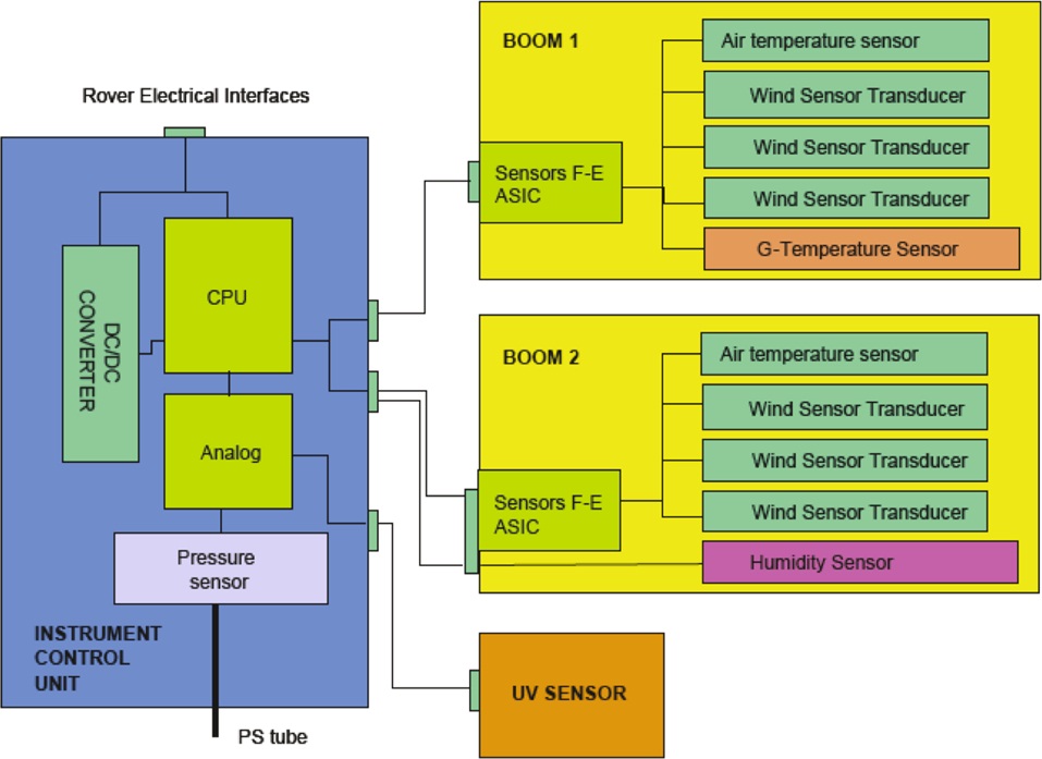
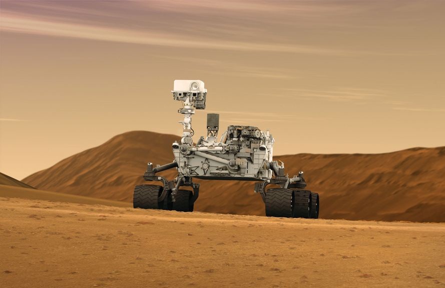
REMS is a meteorological instrument suite that records six atmospheric properties: wind (speed and direction), pressure, relative humidity, air temperature, ground temperature and ultraviolet radiation. The instruments are located at three locations on the rover, two booms that are attached to the Remote Sensing Mast, the Ultraviolet Sensor (UVS) assembly on the rover deck and the Instrument Control Unit (ICU) inside the rover body.
Instrument Booms
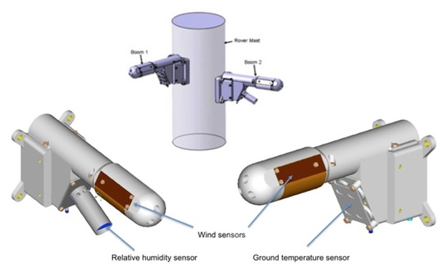
The Booms are about 1.6 meters above the ground. Mounted on the RSM, the booms have about the length of the mast diameter and are separated in azimuth by 120° to make sure at least one mast gets exact wind data at any given wind direction. To minimize wind perturbation from the other boom, there is a height difference of 5 centimeters between the devices. The booms are located 38 and 43 centimeters above the rover deck to minimize rover body perturbations.
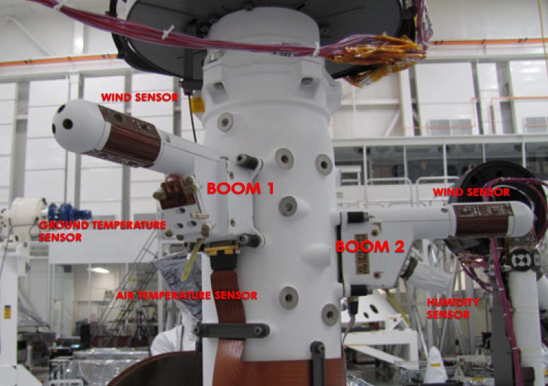
Boom #1 looks to the side and slightly to the rear of the rover and has wind sensors and the ground temperature sensor installed on it. The other Boom (#2) points in the driving direction and has the relative humidity sensor as well as another set of wind sensors. Both Booms are equipped with air temperature sensors. Also, part of each boom are Application-Specific Integrated Circuit-based Sensor Front-End (SFE) Electronics.
Boom #1 is 151.27 by 56.18 by 92.4mm in dimensions and weighs in at 154 grams while the second boom is 151.08 by 56.16 by 93.77mm in size and weighs 147 grams.
Ground Temperature Sensor – GTS
The REMS Ground Temperature Sensor is installed the side-facing Boom #1. Measuring the ground temperature on Mars is important for determination of physical processes involving the surface of the planet such as surface/atmospheric exchange, the energetic drive for turbulence and the water cycle that is active on Mars.
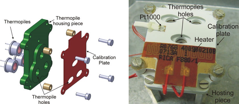
Ground Temperature is recorded with a sensor that views the surface of Mars to the side of the rover through a filter. Temperatures from 150K to 300K can be measured with a resolution of 2K and an accuracy of 10K. This temperature range of the sensor covers the complete spectrum of temperatures occurring on Mars. The GTS (Ground Temperature Sensor) is based on broad-band Infrared Thermopile sensors that uses three filters and electronics to amplify the thermopile sensors. A contact sensor as used on previous missions was not an option for MSL since it would have resulted in fewer operations when the rover performs driving Sols. Also, using thermopiles enables the GTS to operate in the Mars Environment without requiring instrument heaters. The REMS thermopile is the TS-100 manufactured at the Institute for Physical High Technology, Jena, Germany. The thermopile is encapsulated in a TO-5 housing featuring a thermopile filter that was built to specifications and pre-bonded onto the TO-5 as the thermopile window. Inside the encapsulation is an inert Nitrogen Atmosphere as well as a Pt-1000 temperature sensor to provide temperature reference data at the thermopile case base for the thermocouple cold-junction. GTS has a 60-degree horizontal and 40-degree horizontal field of view covering a surface area of about 100 square meters. The sensor is 40 by 28 by 29mm and weighs 20 grams. GTS includes a calibration plate partially in the GTS Field Of View that can be heated up with temperature measurement by a Pt-1000 sensor to provide a calibration source. Since the GTS is facing downward, dust deposition on the sensor is only a minor concern.
Air Temperature Sensor – ATS
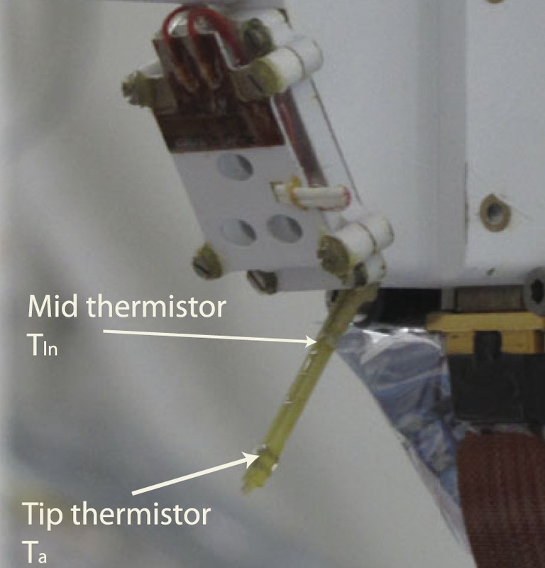
Air Temperature is being measured with two PT1000-type sensor that is installed on a small rod that takes it out of any thermal boundary layers of the vehicle and its components. Its range is also 150-300K. The instrument provides temperature readings at an accuracy of 5K and a resolution of 0.1K.
This high data resolution is required for measuring subtle temperature changes across dynamical features such as fronts, convective cells and dust devils. The rod has been manufactured with a low thermal conductivity material to minimize the measurement contamination due the heat flux from the boom itself. The ATS was designed around thermistors because of their robustness and low response time.
The fin of the ATS is 35mm long and features two Minisens RTD Thermistors, a type of Pt-1000 Class A. Each of those thermistors is 1.2 by 1.6mm in size. The sensors are located at the tip of the rod and at an intermediate position. In addition, another thermistor is mounted on the boom to measure the fin base temperature. Measurements of these three thermistors are used by the REMS algorithm to deduce the absolute air temperature taking into account heat convection and conduction.
The temperature retrieval mode of the REMS ATS algorithm is based on the thermal physics of a thin fin in equilibrium with the fluid around it.
This profile largely depends on conduction through the fin material and the electrical connectors of the thermistors, local convection within the atmosphere, the wind and its associated geometry and atmospheric pressure as well as convection and conduction within the rover and mast system. The REMS algorithm uses the three temperatures (tip, intermediate and base) to record the temperature profile. Having two Air Temperature Sensors enables REMS to look at the difference in between the individual booms to deduce any properties that could cause any errors.
Pressure Sensor
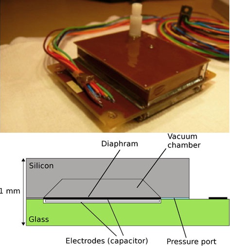
The pressure sensor is located in the rover body and is connected to the atmosphere via a tube that exits the rover through a small opening with dust protection. It operates at a range of 1 to 1150 Pa with an end of life accuracy of 20Pa (calibrations show an accuracy of 3Pa). The instrument provides information at a resolution of 0.5Pa.
The Pressure Sensor Hardware uses two transducers that are placed on a single unit that is 62 by 50mm in size and protected by Faraday Cages. It is located inside the REMS Instrument Conditioning Unit electronics box. Each pressure transducer has 2 Vaisala Barocap® pressure sensor heads and 2 Thermocap® temperature sensors. The pressure sensor heads are of different types: one is of high stability while the other three are of high-resolution type. The pressure sensor heads are single-crystal silicon micromachined devices detecting capacitance changes that are measured via capacitor plates are are moved by pressure. The REMS pressure transducers have flight history on previous interplanetary missions and are known to provide stable measurements in a range of environments. The pressure heads feature higher inaccuracies just after start-up during instrument activation. That is why pressure sensor data is recorded late in each of the REMS measuring increments.
Wind Sensor
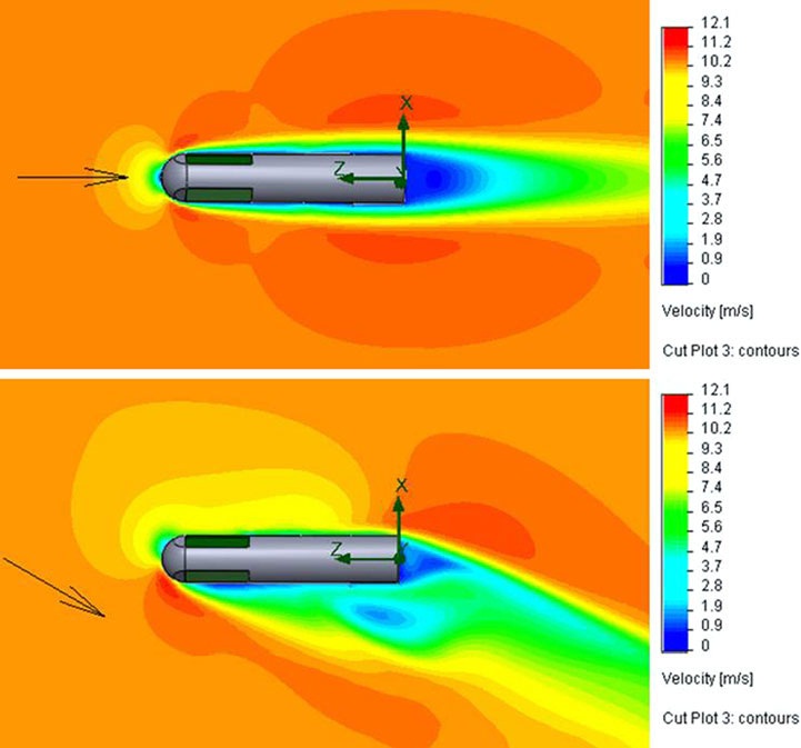
Wind speed and direction is deduced from information by three two dimensional wind sensors on each boom. Located at a separation of 120° around the mast axis each boom records local wind speed and direction in the plane of the sensor. These data points are sufficient to determine speed as well as pitch and yaw angles of each boom relative to the air flow direction.
An algorithm has been developed for boom selection and data processing. Wind data is being provided at a resolution of 0.5m/s and an accuracy of +/-1m/s for speeds between 0 and 70m/s for horizontal winds. The range for vertical wind is 0 to 10m/s. Directional accuracy is expected to be better than 30°.
REMS uses thermal anemometry to record the wind speed. Hot wire anemometry measures the amount of power required to heat a wire so that it maintains a constant temperature difference with the ambient temperature in the fluid wind environment. This can also be achieved by measuring the temperature profile of a wire while using a constant amount of power to heat it and calculating the convective power to deduce wind speed. REMS uses a titanium thin film resistors patterned on the surface of a silicon chip instead of wires.
An algorithm of Boom selection depending on wind direction has been developed during instrument development and calibration. For predicted wind direction between –90 and +90 degrees, Boom 2 is selected. Boom 1 is selected for predicted wind directions of +90 to +270 degrees. When predicted conditions are not fully contained in one of the two intervals, both Booms are receiving a distorted flow and Boom 2 is selected because it has shown more accurate behaviour during calibration in distorted environments.
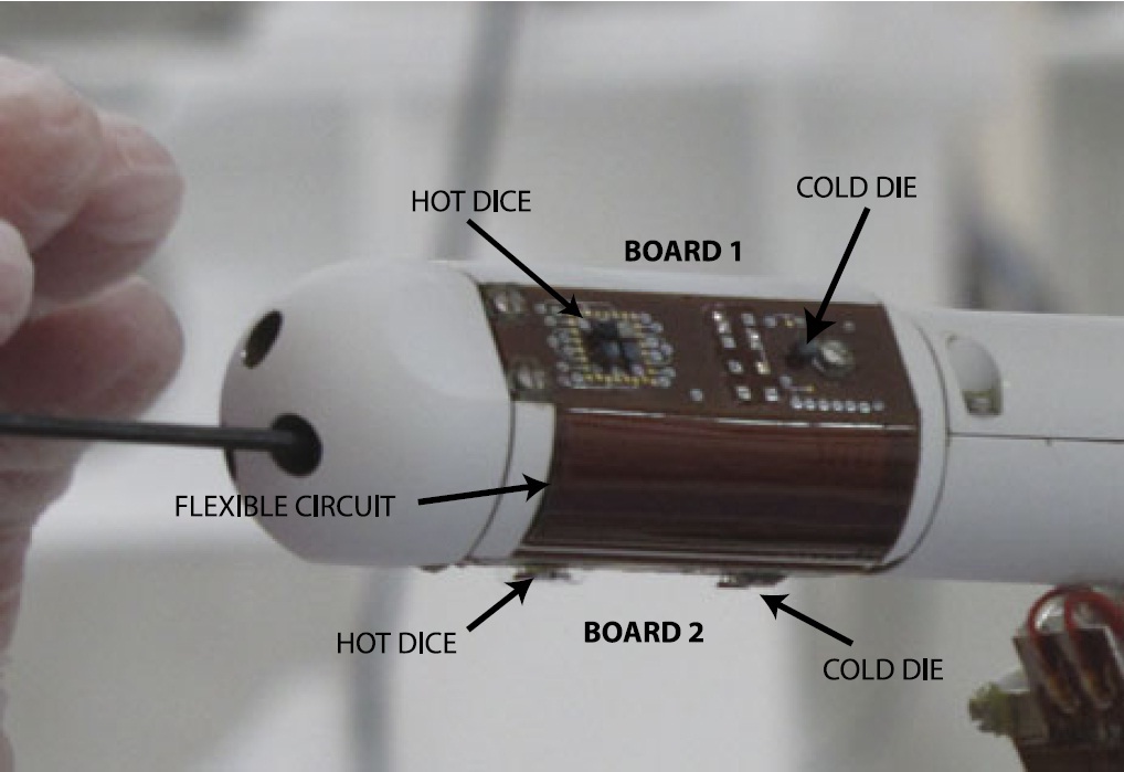
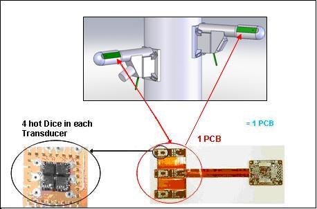
On each boom, there are three Wind Sensor circuit boards, Boards 1 and 3 are on the sides and exposed to the atmosphere while Board 2 is in the lower part of the Boom. Flexible Circuit Boards are used to connect the individual Boards and Board 2 to to the Application-Specific Integrated Circuit. Each board has four hot dice and a single cold die. The hot dice are in the front of the board while the cold die is in the back. All dice are identical and consist of silicon. They each have three resistors printed on the upper side and are thermally isolated from the board by four pillars that have a low thermal conductance. The hot dice use one resistor to heat them, one to measure the temperature and one as reference sensor in the measurement circuit. In the cold die, the only active resistor is the reference resistor. The WS control loop compares the temperature of the hot and cold dice to control the power that is injected to keep a constant temperature difference between them. On each board, there is an additional thermistor that is used to measure the temperature and to evaluate the conductive thermal losses of the dice.
Humidity Sensor
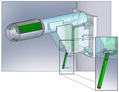
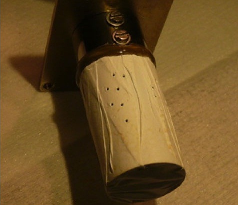
The Humidity Sensor on Boom #2 is mounted inside a protective cylinder. It measures relative humidity with an accuracy of 10% within a temperature range of 200-323K and a resolution of 1%. A dust filter will prevent any dust from interfering with the sensor.
The HS transducer includes 3 Humicap® sensor heads and 1 Thermocap®. REMS’ Humidity Sensor is 36 by 15 mm in size and is enclosed in a metallic Faraday cage. The sensor heads contain an active polymer film that changes its capacitance as a function of relative humidity with a full measurement range. The film continuously reacts to the humidity environment as part of the chemical process the polymer goes through in changing humidity conditions. This means that, at instrument start up, there is no delay and accurate humidity data be taken within one second to allow for electronics stabilization. Nominal capacitance of Humicap® is in order of 6 pF.
The humidity sensors have a time-lag that increases with temperature. The sensor heads have Pt heating resistors that are used to heat the sensors to up to 150°C as part of instrument maintenance. Heating the polymer up removes any contaminants and regenerates the nominal chemical behavior of the system.
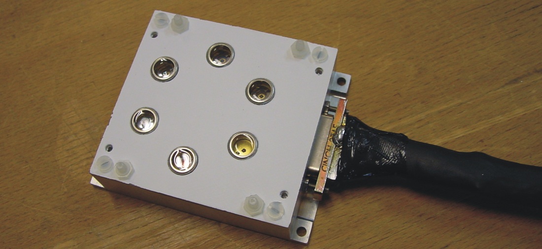
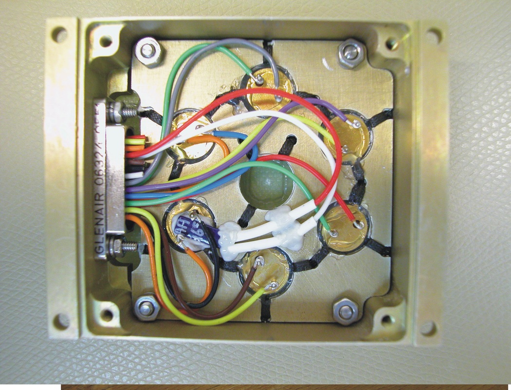
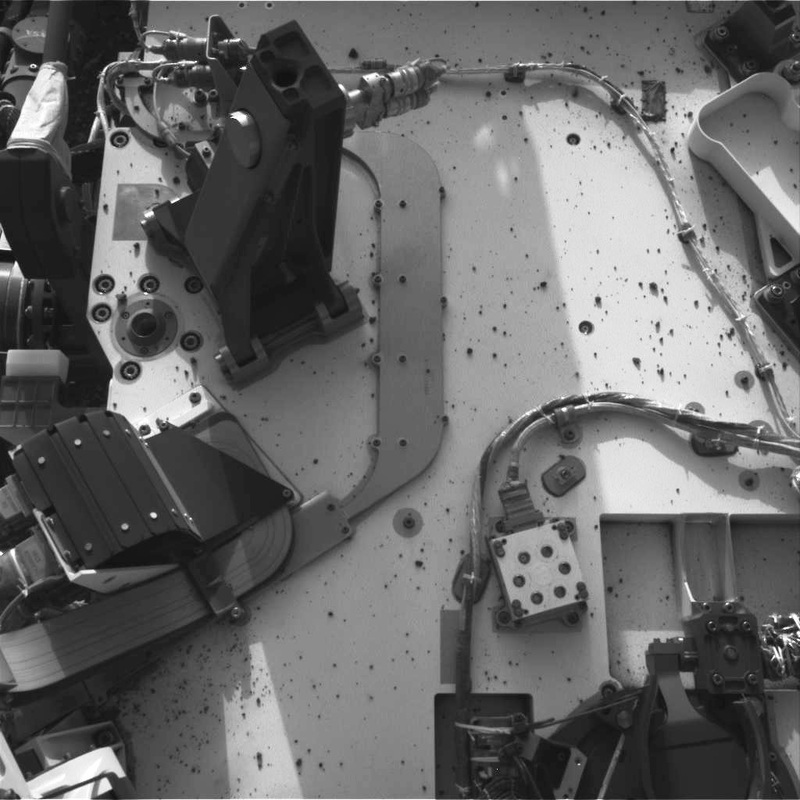
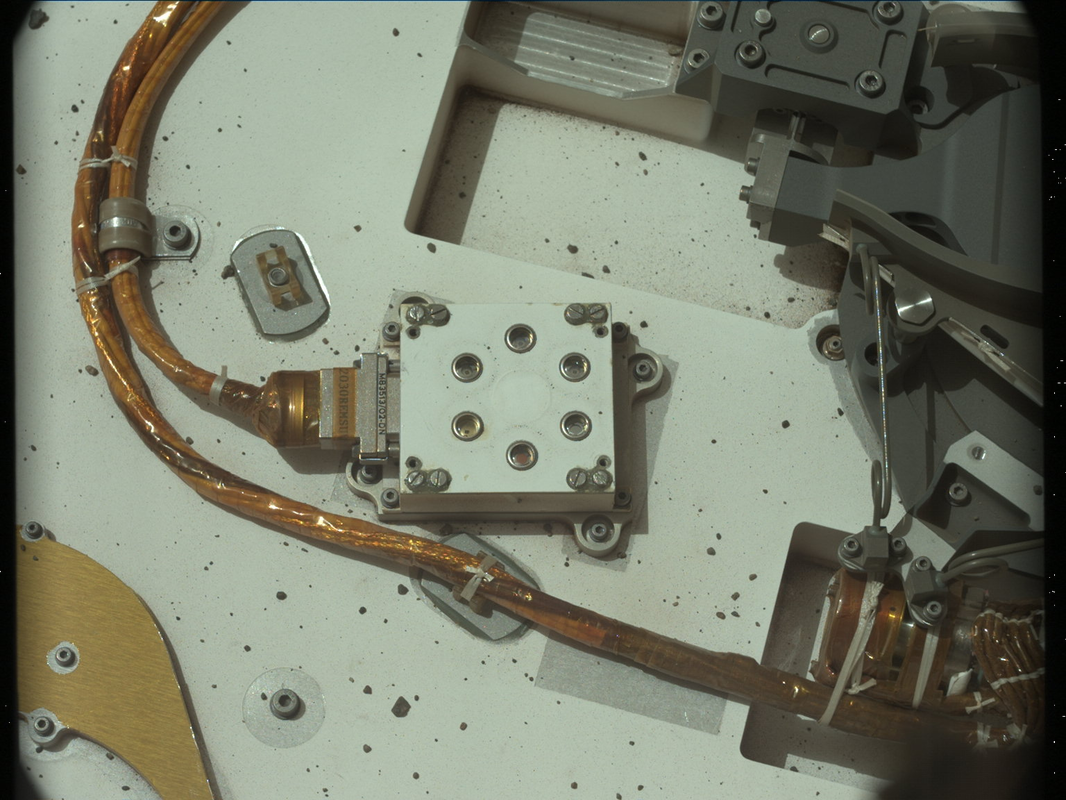
UV-Sensor – UVS
The UV Sensor assembly is located on the Rover Deck and is comprised of a total of six photodiodes that were provided by Ifw Optronics GmbH. Each diode covers a different spectral area to broaden the UVS spectrum. Using UV photodiodes provide advantages such as their robustness as well as stability in terms of data return. The UVS faces the sky and is located on the Rover Deck at a location that allows it to be imaged by the NavCams and MastCams to monitor the instrument. Each UVS photodiode weighs 1 gram and is enclosed in a TO-5 housing that is 5 by 5mm. The diodes have a SiC sensing surface of 1mm². When the sun is within the +/-30-degree field of view, the direct beam reaches the sensing surface. Each diode is embedded in a magnetic ring that is used to keep magnetic durst from accumulating on the sensor surface which degrades data quality. Regular NavCam images of the UVS are acquired to allow teams to assess dust deposition.
The individual diodes cover a combined spectrum of 200 to 380nm. “The selected photodiodes have different spectral ranges: one global (named ABC) SiC photodiode with responsivity in the range 200–380 nm, and 5 filtered photodiodes named A, B, C, D and E. Each broadband photodiode shall provide an approximate evaluation of the incident flux within its range of responsivity: photodiode C provides a first order estimate of the level of biologically damaging irradiance; the outputs of photodiodes A and B are to be compared with terrestrial irradiance while photodiode ABC gives an estimate of the total UV irradiance, and photodiodes D and E are designed to match two UV channels of the MARCI instrument on board the Mars Reconnaissance Orbiter (MRO) satellite such that a direct comparison with simultaneous reflectance measurements is possible.” [J. Gomez-Elvira et al., 2012] The instrument will provide readings at an accuracy of 8%.
Sensor Front-End Application-Specific Integrated Circuit
On each boom, a single ASIC is mounted. These devices are integrated circuits that receive all the low level analog signals generated by the individual instruments. The ASIC converts these signals to digital signals that are then transmitted to the Instrument Control Unit. The ASIC circuit includes constant current sources that are used to supply power to the Pt-1000 sensors (ATS, GTS) and measure the voltage drops that are converted to digital values, amplified and transmitted to the ICU. Also, the currents for the 12 hot dice of the WS a generated by the ASIC that in turn receives the signals from the electro-thermal sigma-delta control loop and converts them into counts. The temperature of the ASIC circuits is controlled via the ICU that powers heaters and thermistors bonded to each casing.
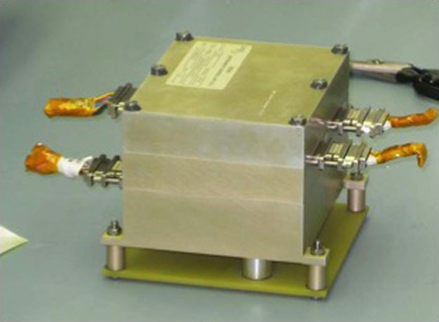
Instrument Control Unit
The heart and brain of REMS is the ICU that monitors and controls all of the sensors and devices of REMS. The unit also includes all interfaces with the rover systems in terms of power supply and data transmission. ICU is located inside the Rover Body where temperatures are kept in a comfortable range. The unit provides power condition for itself and the sensors, system initialization and self testing, communication with the rover, real time clock and alarm counter, operations mode management, instrument timeline execution and data logging, download of science and housekeeping data and it accommodates the pressure sensor.
The ICU consists of three major components: a general-purpose Central Processing Unit, a Power Supply Unit and an Analog/Digital front-end Module. The REMS CPU is based on a radiation hardened version of the Intel 80C32 8-bit processor that implements 32KB ROM for boot code storage and 64KB RAM for data management. A 128KB EEPROM provides the application software and a 4MB non-volatile memory chip is used to temporarily store science data that is then transmitted to the rover for downlink.
The Power Supply Unit receives primary power from the rover end generates two secondary power buses that are used by REMS. The PSU includes two DC-to-DC converters and one custom small converter to power the instrument alarm counter during REMS sleep periods. PSU supplies a reliable power supply of 5 volts. The Analog/Digital front-end Module acquires and digitizes the low level signals coming from the UV Sensor as well as other housekeeping signals.
REMS Operation
REMS is actively reading environmental data for 5 minutes during each hour of operation. The instrument suite operates autonomously to a large extent, waking up automatically each hour, taking and storing its data and going back to its sleep configuration. Data will also be recorded when the rover is in its sleep mode and the hourly windows are also planned to occur during Martian Nights. Under certain conditions, the pressure and ground temperature sensors require multiple measurement samples.
REMS operation is constrained by power availability and is limited to three hours each day. The science team has the opportunity to request and schedule any additional measurements that are needed to meet mission objectives. With one hour of additional time each day (the scheduled windows have a total duration of 2 hours), the system can auto detect atmospheric events and extend a scanning period by its own.
For that, an algorithm is implemented that allows the REMS ICU to extend the 5-minute monitoring sessions should certain parameters be met. This enables the system to automatically detect any scientifically interesting situations to take advantage of those. In addition to these event triggered operation cycles, ground teams can command REMS to operate for longer increments to obtain a continuous data set of up to several hours.
REMS Objectives
- Provide information on Signatures of the Martian general circulation and mesoscale phenomena near the surface
- Study Microscale Weather Systems
- Investigate the Local hydrological cycle
- Determine the destructive potential of UV-Radiation, dust UV properties, photolysis rates and oxidant production
- Contribute to the evaluation of subsurface habitability based on ground-atmosphere interaction
REMS Design