MarCO – Mars Cube One
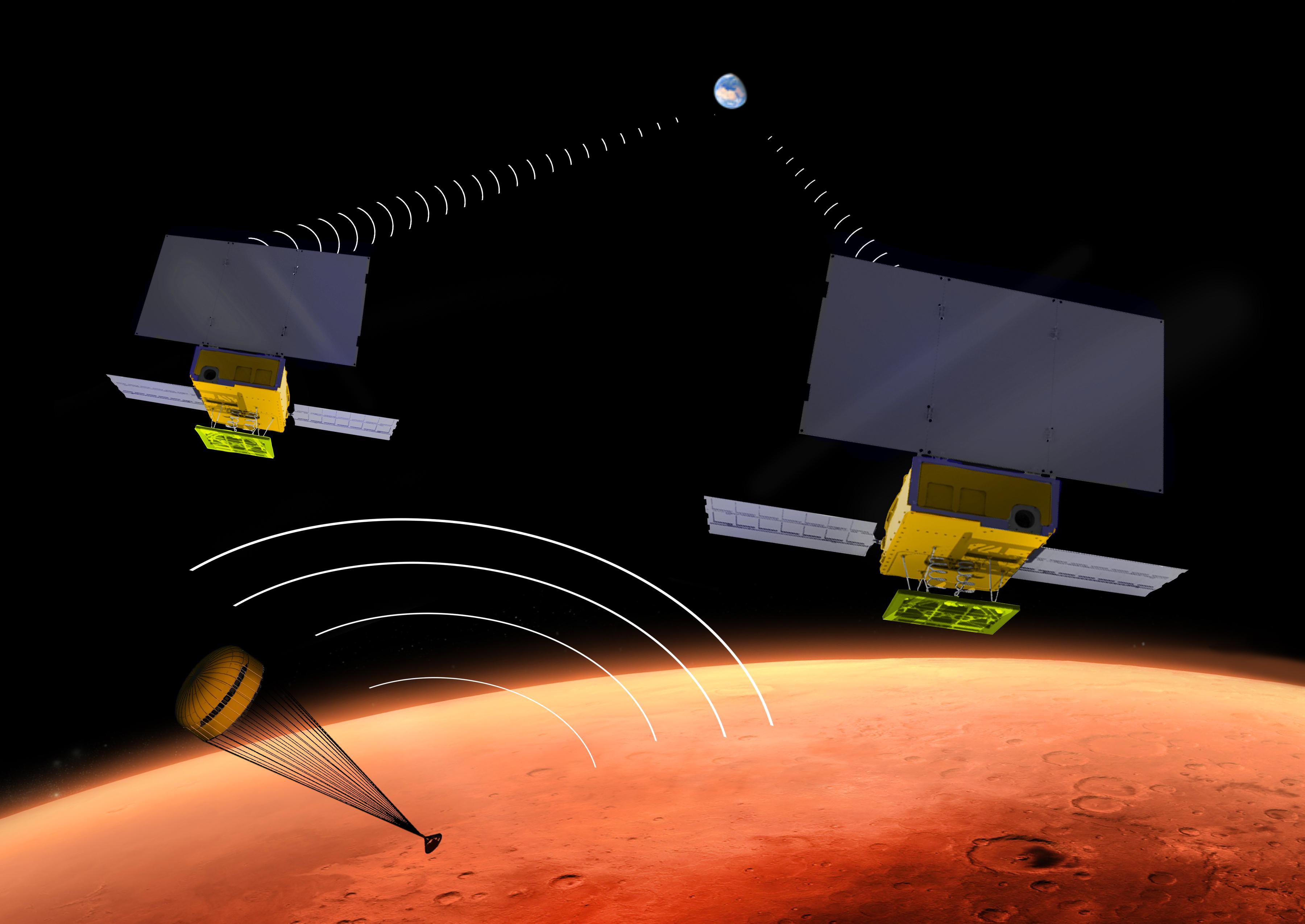
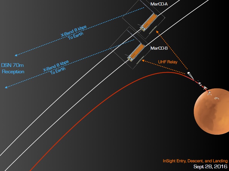
Mars Cube One, MarCO for short, is a CubeSat mission of NASA’s Jet Propulsion Laboratory comprising two functionally identical six-unit CubeSats accompanying the InSight Mars Lander to provide communications relay during the Entry, Descent and Landing phase when the lander will not be able to directly communicate with Earth.
MarCO is the first CubeSat mission to operate between Earth orbit and its primary objective is a proof-of-concept mission to show CubeSats can be of use for interplanetary exploration; the InSight mission is not contingent on MarCO’s success in any way.
CubeSats have been around since the turn of the century, originally envisioned as a standardized small satellite platform to enable cost-effective access to space for educational institutions. However, as technology matured, miniaturization of previously large systems for communications, meteorology and Earth observation enabled them to fly on CubeSats – making them attractive for industry. The number of CubeSats launched into orbit literally exploded since 2013 with the deployment of large constellations for commercial and research purposes.
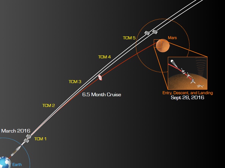
Flying CubeSats beyond Earth orbit was seen as a logical next step to continue expanding their operational reach and the InSight mission was a prime opportunity for proving the use of the small satellites in an operational capacity in deep space. The MarCO project features two identical satellites for redundancy, launching alongside InSight on its Atlas V 401 rocket to be sent toward Mars on a similar trajectory. While InSight will alter its course toward a landing site on Elysium Planitia, the two CubeSats will maneuver onto a flyby trajectory to capture telemetry from InSight in the critical minutes of its landing maneuver.
The MarCO demonstration will offer valuable knowledge for a future operational capability of having small satellites shadow a lander mission to relay communications during EDL.
Previously, NASA’s Mars landers relied on orbiting spacecraft to capture their short-range telemetry signals and relay them to Earth in real time or store them for later playback. However, orbiters are not present on every Solar System body that may be targeted by a future lander mission since their deployment is a costly and complex undertaking. Developing small CubeSat-based relay spacecraft shadowing the lander on its trip may provide a solution for this problem.
The MarCO mission was also born out of a desire to have a redundant communications relay for the InSight mission since only the Mars Reconnaissance Orbiter – at the Red Planet since March 2006 – will be in position to cover the InSight EDL. Should MRO encounter a serious problem before the spacecraft arrives, there would have been no means for collecting telemetry from the lander – an undesirable situation since real-time data is critical in the event of a failed landing.
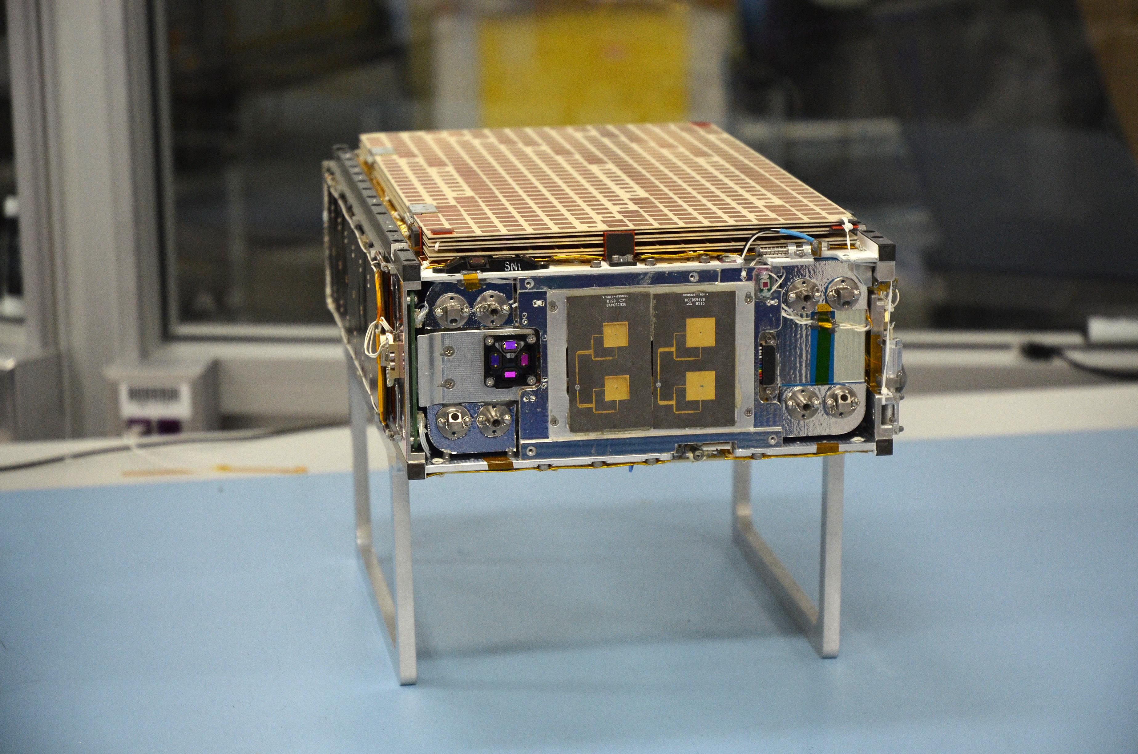
The two MarCO satellites comply with the 6U CubeSat form factor, each being 10 x 20 x 30 centimeters in size and weighing 14 Kilograms.
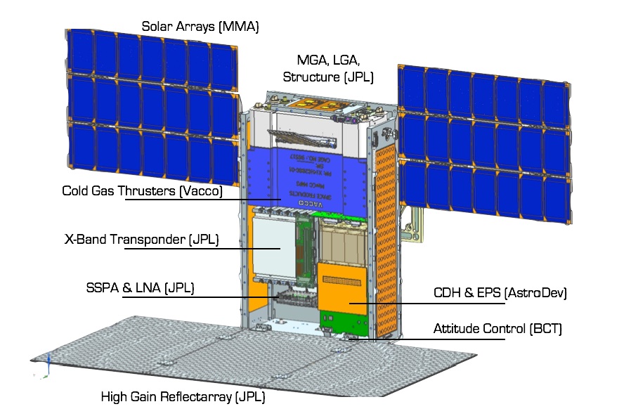
The satellites are outfitted with two deployable solar arrays to generate sufficient power even at distances beyond the orbit of Earth, a UFH receiving antenna to capture telemetry from InSight and a deployable X-Band antenna reflector to re-transmit data to Earth at a speed of 8 Kilobits per second. Both CubeSats are propulsive spacecraft, hosting cold gas propulsion systems to alter the course to set up the proper timing and geometry for the flyby.
The two CubeSats will launch on the aft bulkhead carrier of the Centaur Upper Stage of AV-078, deployed by a pair of Tyvak NLAS Mark II dispensers around 95 minutes after liftoff.
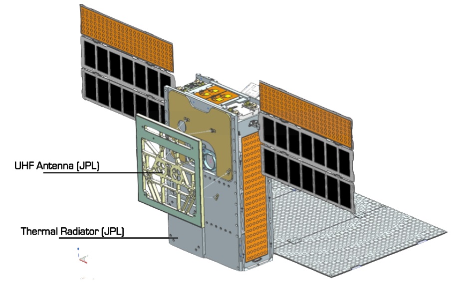
The MarCO CubeSats host several deployables: two three-panel solar arrays are stowed against the 30 x 10-centimeter side panels, the three-panel X-band reflector array is stowed against one of the large 20 x 30-centimeter panels and the UHF receiving antenna occupies the other large side panel.
The Electrical Power System of the MarCO satellites was provided by MMA, LLC, AstroDev and the University of Michigan. It comprises two three-panel solar arrays, each covered with 21 triple-junction GaAs solar cells to generate 35 Watts of electrical power at the distance of Earth (1 AU). Deployment of the arrays is completed by loaded springs and they rotate upon deployment but will remain in a fixed position for the remainder of the flight.
The solar arrays feed four input channels to the single set-point power architecture that conditions a 12-Volt battery bus to charge a Li-Ion battery consisting of three strings of four parallel cells. The power system also conditions the 5 and 3.3-Volt buses distributed to all loads on the satellite and custom-made circuitry provides battery protection and monitoring functions for the Command and Data Handling Subsystem.
The MarCO satellites are three-axis stabilized through a typical CubeSat Attitude Determination and Control System based on several attitude determination inputs and reaction wheels for actuation. Since MarCO will not have the Earth’s magnetic field to work with, magnetic torquers are no option for momentum unloading from the wheels – requiring a propulsive attitude control system to be implemented in addition to a main propulsion system for trajectory control.
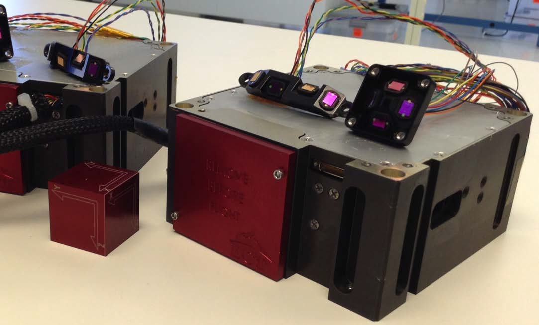
Chosen for the MarCO mission was Blue Canyon’s XACT (fleXible Attitude Control Technology) unit which includes a star tracker, inertial measurement sensors, coarse sun sensors and a three-axis reaction wheel assembly for actuation. The XACT unit takes up 0.5 Units of volume (10 x 10 x 5 centimeters) and weighs 0.91 Kilograms when flying in its baseline configuration, capable of a pointing accuracy of ±0.003 degrees on two axes and ±0.007 on the third. It uses a 12V power supply, supports slew rates of over 10° per second and has been rated for a five-year lifetime on Low Earth Orbit missions.
Several modifications on the XACT baseline design were needed for the MarCO mission and include the addition of a coarse sun sensor and provisions for controlling the thruster system for momentum control, facilitated on a functionally separate unit from a different manufacturer. Changes were also needed in the flight software to account for deep space trajectories.
Through the cruise phase, the Star Tracker is the primary attitude determination device, collecting imagery of the star-filled sky that is compared to an onboard catalog of over 23,000 stars to identify known constellation and from that calculate the craft’s precise three-axis orientation.
The XACT Star Tracker typically processes up to 64 guide stars down to 7.5 mag and delivers attitude quarternions at a refresh rate of five per second. The inertial measurement system is used to propagate the state of the craft in between ST updates and it also provides guidance for the initial de-tumble of the spacecraft after separation from the launch vehicle. One interesting function of the XACT Star Tracker is its imaging mode, capable of collecting black and white images of 1024 x 1280 pixels.
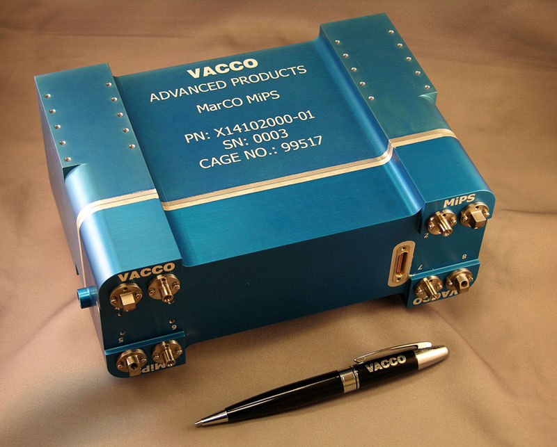
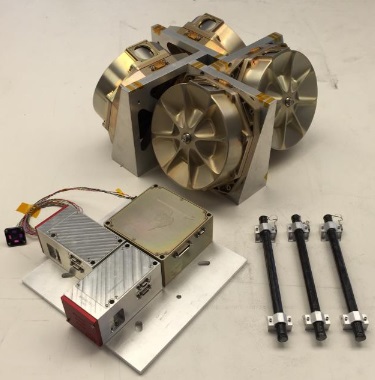
The Propulsion System selected for the MarCO CubeSats is the Vacco MiPS (Micro CubeSat Propulsion System), a system-in-a-tank design containing the propellant storage system, feed lines, thrusters, control electronics, and sensors. The self-contained system uses an all-welded aluminum structure and hosts eight cold gas thrusters delivering 25 millinewtons of thrust each. Four are arranged to deliver delta-v as part of Trajectory Correction Maneuvers while the other four are canted to provide attitude control and reaction wheel unloading.
The 3.49-Kilogram MiPS consists of a Propellant Storage Tank holding the R-236FA propellant in a two-phase system with a liquid and gaseous phase present in the spherical tank assembly. Gaseous propellant is directed through a 10-micron filter and a heated line featuring a Pressure Control Valve into a second tank that only holds propellant in is gas phase, controlled by a heater element with feedback from thermal and pressure sensors.

This tank essentially acts as a plenum to ensure gaseous propellant is available at the proper pressure, fed to the individual thrusters via controllable engine valves. Thrust can be varied as needed through adjustment of the Vapor Tank pressure by setting three thermal control zones (the storage tank, feed line and Vapor tank).
The MiPS as flown on MarCO has a total impulse of 755 N-sec, translating to a delta-v budget for the satellite around 40 meters per second. MiPS has a total of three power supplies for its subsystems and incorporates nine valve drives (eight for the thrusters and one for the Pressure Control Valve). Its standby power demand is 0.5 Watts to keep components at survival temperatures.
The MarCO mission foresees up to five trajectory correction maneuvers over the course of the Cruise Phase. One mandatory TCM occurs in the first two weeks after launch to correct any inadvertent injection errors by the launch vehicle and reduce a deliberate targeting offset that is in place to ensure the Centaur upper stage misses Mars by a safe distance. Up to four additional TCMs can be performed to set the proper geometry and timing for the flyby, targeting a distance of 3,500 Kilometers.

The Command and Data Handling Subsystem of the MarCO satellites employs a central CDH board designed by AstroDev based on the INSPIRE and RAX missions. It contains non-volatile storage, a real time clock, cascaded watchdog systems, and input/output interfaces for SPI, I²C, UART, GPIO and RS-422 to communicate with the various satellite subsystems. MarCO runs a custom-made software called protos based on a real time operating system using 128 kB of flash and 8 kB of RAM.
The Thermal Control System for the MarCO mission comprises two discrete radiator elements, thermal blanketing, onboard heaters and a series of temperature sensors. Given their interplanetary mission, the two satellites have a design that carefully balances radiator sizing against subsystem duty cycles, power usage and replacement heaters to ensure a stable thermal design can be achieved with the resources available during the flight.

The heart of the MarCO CubeSats is their communications architecture: an Iris v2 Software Defined Radio with four receive and transmit ports. Mission Communications for satellite control are handled by redundant Medium- and Low-Gain Antennas installed on one of the smaller 10 x 20-centimeter satellite side panels; the Low Gain Antennas will be in use during the early cruise phase before the mission transitions to the MGA during the approach to Mars.
The communications payload employed for the InSight relay comprises a microstrip antenna, a High Gain Reflectarray, an X-Band Transponder, a Solid-State and Low-Noise Amplifier Assembly and a UHF loop antenna deployed from the bottom of the spacecraft. MarCO will receive real-time data from InSight at 401.586 MHz and a data rate of 8 Kilobits per second which is then re-packaged into a Deep Space Network compliant format and transmitted through the 4-Watt X-Band microstrip antenna patch.
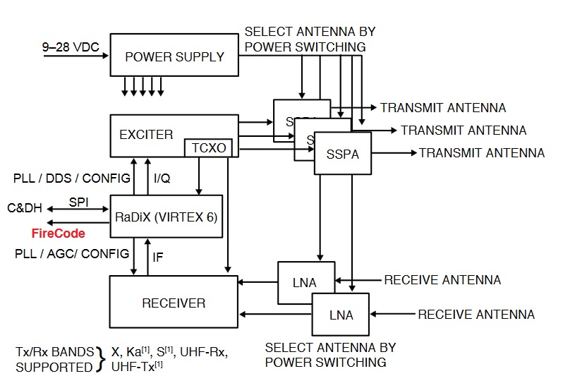

The Iris v2 radio, developed by NASA JPL, consists of five stacked modules with external Solid-State Power Amplifier and Low-Noise Amplifier Modules. Iris v2 itself weighs 1.2 Kilograms, takes up 0.5 CubeSat units of volume and requires a peak power of 35 Watts when transponding at a four-watt X-Band RF output. It is fully compatible with the Deep Space Network, operating at a downlink frequency of 8.4 GHz and 7.2 GHz for uplink. It has been designed to be radiation tolerant for deep space missions of several years and includes thermal regulation provisions for tracking/navigation sessions of several hours at a time.
The stacked architecture with five circuit boards allows Iris to be easily modified by substituting slices to allow for easy extension and adaptation to new capabilities like additional frequency bands and compatibility with different ground receivers. In its baseline design, Iris v2 relies on a Virtex 6 Digital Processor Module hosting a LEON3-FT CPU, 32 Mbit of non-volatile flash, 16 Mbit volatile SRAM and 4 Mbit volatile SRAM, all radiation tolerant for deep space missions. The Digital Processor Module is tasked with the modulation and demodulation of signals, radio reconfiguration, health status reporting and link layer protocol handling.
The Solid State Power Amplifier in the transmit chain provides three RF paths to three antennas, selectable via power switching while the LNA in the UHF receiving segment has two RF paths connected to the Receiver.