
Cygnus OA-6 Cargo Overview
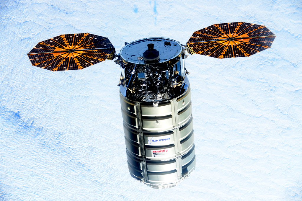
Cygnus OA-6 is the fifth operational flight of the Cygnus cargo spacecraft to the International Space Station, the second to use the Enhanced Cygnus version and the second of two launching on the Atlas V rocket. Orbital ATK contracted United Launch Alliance in late 2014 for a pair of Cygnus launches atop the Atlas V in the wake of the Orb-3 launch failure to allow Orbital ATK to re-fit the Antares launch vehicle with new engines for a return to flight with the OA-5 mission in mid-2016.
Cygnus OA-6 is the first flight of the SAFFIRE Spacecraft Fire Experiment that will examine how fires spread in a spacecraft for the improvement of the fire safety on future spacecraft. SAFFIRE will start an internal fire within an experiment enclosure after Cygnus has left ISS, allowing scientists to safely study the properties of larger fires in space which has not been possible in the past.
Taking advantage of the power of the Atlas V rocket, Cygnus can be packed to capacity, delivering 3,395 Kilograms of cargo, continuing to make up for lost upmass in the Orb-3 failure. The OA-6 mission is expected to lift off in March 2016 and the spacecraft is booked for a stay of nearly two months to allow the six crew members in orbit to unload the cargo from the spacecraft and place around 1,726 Kilograms of disposal items on the spacecraft.
The Cygnus OA-6 spacecraft is loaded with supplies for the crew comprised of food, hygiene articles, personal items and clothing, as well as systems hardware and replacement parts for the various onboard systems on the U.S. Segment, spacewalking equipment and computer resources. Also, Cygnus is delivering new science facilities and experiment equipment for several dozen experiments in progress during ISS Expeditions 47 and 48.
Total Cargo: 3,279kg (With packaging: 3,395kg)
Science Hardware: 777kg
NASA: ARTE, METEOR, STRATA-I, SPHERES Docking Port, SAFFIRE-I, Additive Manufacturing Facility, Various Combustion Integrated Rack & Human Research Facility Supplies
CSA: MARROW, Vascular Echo
ESA: Airway Monitoring, ENERGY, Fluid Science Laboratory
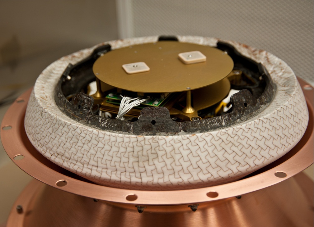
JAXA: Cell Biology Experiment Facility 1G centrifuge, BLR48, J-SSOD Satellite Deployer, Exposed Facility Unit adapter with GPS Wheel Demo
Crew Supplies: 1,139kg
169 Cargo Bags of Food Provisions
6 Cargo Bags of Food Provisions for Russian Crew
Hygiene Equipment for Russian Crew
Printing Paper & Ink
Vehicle Hardware: 1,108kg
MDM Circuit Card Replacement
ECLSS Replacement Parts
Water Sampling Kits
Waste & Hygiene System Replaceable Parts
EVA Equipment: 157kg
EMU Components: Legs, boots, Hard Upper Torso
METOX Carbon Dioxide Scrubbers
Contamination Detection Equipment
Computer Resources: 98kg
Laptop & Printer
Hard Drives & Assorted Cables
Camcorders and Cameras, associated components
SAFFIRE
SAFFIRE-I, the first Spacecraft Fire Experiment, will intentionally light a large-scale fire inside the Cygnus spacecraft after its departure of ISS, a few days before it re-enters Earth’s atmosphere. Only very few experiments were run to study combustion and fire processes in microgravity, let alone large-scale fire progression within a spacecraft. SAFFIRE aims to study a realistic fire on a space vehicle, looking at flame growth, temperatures and oxygen use to assess how microgravity and limited oxygen affect the properties of a fire. Data from SAFFIRE will be used to improve fire safety on future crewed spacecraft and help NASA in choosing materials for future vehicles.
Despite decades of combustion experiments run in space, only few tests have studied spacecraft fire safety and none have studied environment sizes typical for a spacecraft fire due to obvious concerns of running this type of experiment in an inhabited spacecraft. Due to the lack of firm data, spacecraft manufacturers use models and standards for terrestrial fires when designing spacecraft fire safety systems. Although this approach has been successful thus far, there is inherent risk due to the level of uncertainty in modeling large-scale fires in space. SAFFIRE proposes to set fire to material samples around one meter in size to study large-scale flame growth and fire dynamics not possible within the experiment facilities of ISS.

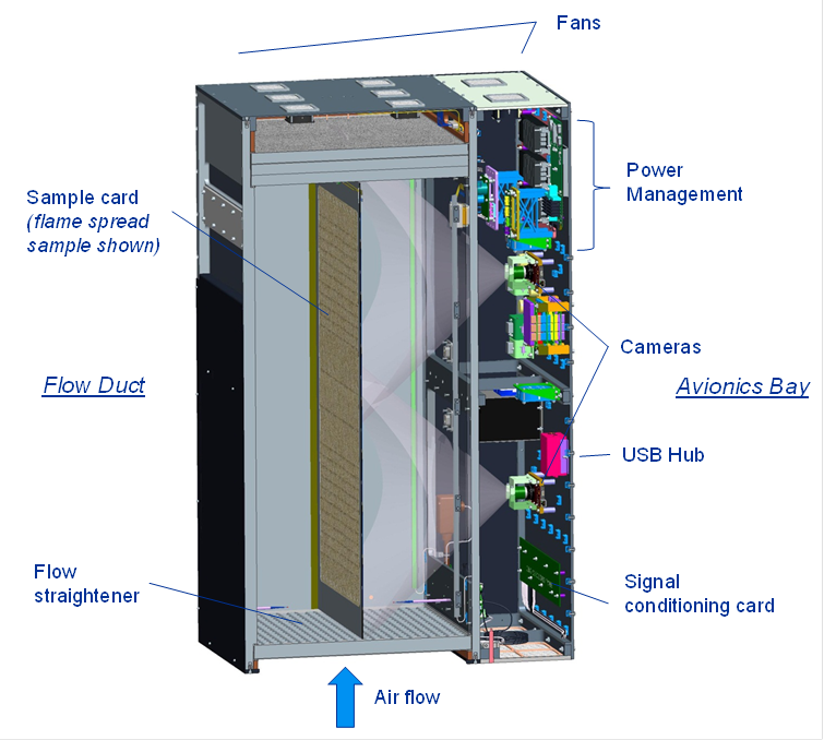
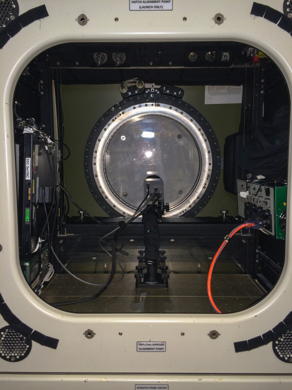
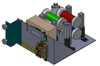
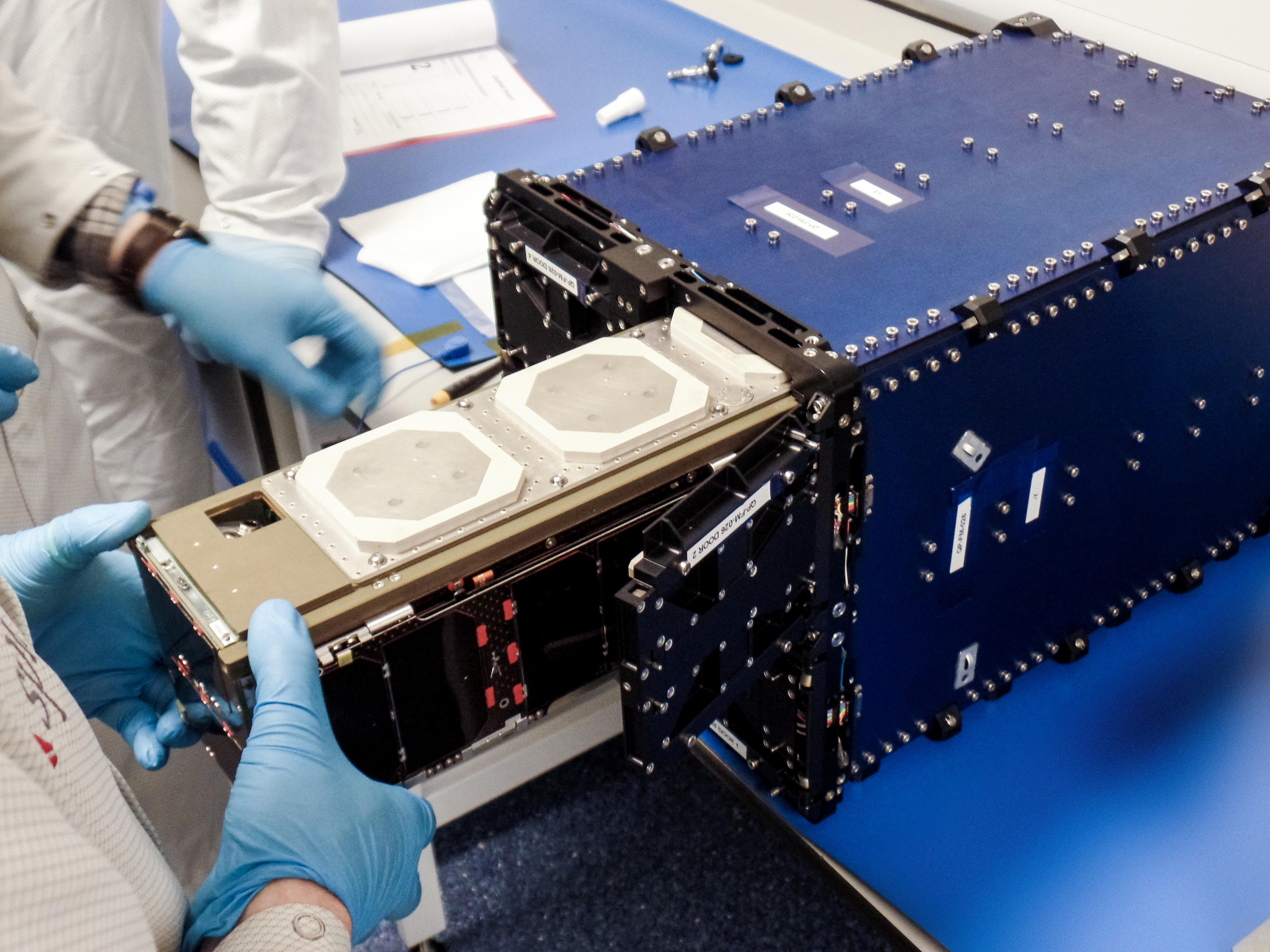
The SAFFIRE experiment package consists of a flow duct and an adjacent avionics bay housing various sensors and associated power and data systems. Atop the flow duct is a fan creating air flow through the system and on the bottom is a grid serving as a flow straightener.
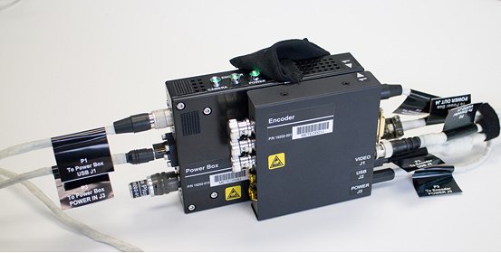
The SAFFIRE Experiment Unit measures 53 by 90 by 133 centimeters in size comprised of the larger flow duct and the avionics bay occupying the smaller volume, the entire unit affixed to internal spacecraft structure with conventional cargo straps. Within the avionics section are power management units, two cameras, a USB Hub and signal conditioning electronics receiving data from the sensors, compressing it and sending it to the spacecraft for downlink.

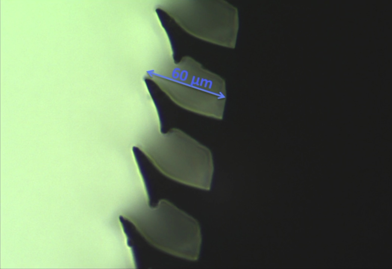
Installed within the system are temperature, oxygen and carbon dioxide sensors located at the intake of the flow duct and upstream of the fans. A pressure sensor and flow anemometers are placed at select locations to quantify the oxygen inflow. A pair of video cameras provide views of the sample and an LED light source periodically illuminates the sample to allow the measurement of the pyrolysis length.
For flame spread experiments, thermocouples are placed at varying lengths above the sample and a radiometer measures the broadband radiative emission from the sample to calculate the radiative heat flux from the sample towards its surroundings.
The sample material is approximately 0.4 by 1.0 meters in size, consisting of a panel of thin material. Ignition is accomplished with a hot wire along the upstream edge. The SAFFIRE-II test will use nine sample strips of 5 by 30 centimeters to assess the Maximum Oxygen Concentration (MOC) flammability limits of different materials.
The SAFFIRE I and III experiments will use a 40-centimeter wide and 94 centimeter long sample of 75% cotton and 25% fiberglass blend burned at two different flow speeds.
Meteor
The original Meteor hardware was expected to arrive aboard the International Space Station in October 2014 on the Cygnus Orb-3 resupply craft that unfortunately was lost in a launch failure of its Antares launch vehicle just seconds after lifting off.
Re-flight hardware, using an already existing spare, began assembly shortly after the failure given the scientific return expected from this interesting study. This spare unit was placed on the Dragon SpX-7 spacecraft for a ride to ISS but never made it into orbit when the Falcon 9 rocket experienced a catastrophic failure in its second stage pressurization system. A third Meteor Unit was commissioned to finally take its spot aboard ISS to watch meteors in Earth’s atmosphere from its unique vantage point high above.
The Meteor study, going by the full name of ‘Meteor Composition Determination,’ is the first of its kind to be deployed in space, solely focused on the analysis of meteors entering Earth’s atmosphere and pin-pointing their composition through their optical emissions when burning up in the atmosphere. Meteor research from Earth is next to impossible due to the frequency of meteor events over any given location and the interference created by Earth’s atmosphere (ozone absorption). On ISS, however, crews can spot meteors every couple of days, making it a suitable platform to test out equipment for the study of meteors.
The Meteor payload consists of high-resolution imagery and video equipment that will capture images and video of Earth’s atmosphere that is processed by a software to identify bright spots. These meteor events can then be analyzed spectrographically. Created spectra can be compared to known synthetic spectra to identify element abundances and temperatures. It is hoped that Meteor can deliver valuable data on absolute meteor flux and provide information on carbon-based compounds in meteors.
Meteor is a high-resolution spectrographic imager that will operate for two years inside the Window Observation Facility to create a continuous record of meteor activity. The camera is outfitted with an infrared cut filter and only looks at visible wavelengths up to 700 nanometers which is sufficient to conduct spectral analysis and determine a meteor’s elemental composition. Major emission lines that will be looked at include iron (370nm), calcium (393nm), magnesium (518nm) and sodium (589nm). Although the Window Observation Facility window has a limited transmittance at the 370nm wavelength (~21%), measurements of that line will still be useful for the study.
For many meteor shower events, the parent comet or asteroid is known, enabling this experiment to deliver data on cometary composition which is of great interest to scientists. Additionally, the instrument sets out to obtain measurements outside of the peak of major meteor showers to look at the frequency of meteor events in general. Secondary studies of terrestrial targets and re-entering spacecraft will also be performed.
Strata-I

Strata-I investigates the properties and behavior of regolith, the impact-shattered soil found on asteroids, comets, the Moon and other airless bodies. Regolith is different from soil on Earth in that it contains no living material. The behavior of regolith in microgravity is virtually unknown and has obvious implications when attempting to anchor a spacecraft in regolith. Strata-1 also studies how regolith interacts with spacecraft and spacesuit material and whether it is possible to process large volumes of regolith.
Information from previous missions including NASA’s Stardust, ESA’s Rosetta and JAXA’s Hayabusa-1 have shown that regolith may flow like sediments as asteroids and comets deform. Many asteroids feature low bulk densities and a mechanical structure composed of loosely bound particles which are mostly free to move. Detailed research is needed to better understand regolith physics in microgravity.
The Strata-I experiment facility exposes a series of regolith simulants to microgravity over a prolonged period of time as well as the ambient vibration environment on ISS. The samples are layered in four clear polycarbonate tubes including pulverized meteorite material, glass beads and regolith simulants.

Each tube, with an inner diameter of 6.3 centimeters, includes a device (“Entrapulator) that lightly compresses the material for launch and landing, preventing any movement when not exposed to microgravity. Four HD cameras are part of the Strata-I facility, lighting is provided by white LEDs and imagery is stored on SD Cards that are periodically exchanged and data is transferred to an ISS computer for downlink to the ground.
Changes to the layering of material (stratigraphy), size sorting and particle migration within the tubes will be observed from the ground through video and still imagery. Returned to Earth, the material distribution will be analyzed to look at the behavior of material seen on asteroids, Mars moon Photos and other possible targets for future robotic and crewed exploration.
The materials chosen for Strata-I span a range of complexity from a simple system of glass spheres to more complex systems of crushed meteorite material. Three size species are part of each tube, launched in a perfectly layered arrangement held in place by the entrapulator. The first tube of the experiment contains spherical glass particles with three discrete sizes of 2, 5 and 10 millimeters, each with its own color.
The grain sizes and quantity of each species were chosen based on numerical constraints and to ensure that particle-particle collisions dominate over interactions with the tube. The materials in the second tube have identical properties in terms of size and size distribution, except that this tube features angular particles created by fracturing hemispherical particles and sieving them to achieve the required size distribution. A comparison between Tube 1 and 2 will allow scientists to identify the influence and significance of grain shape on the segregation process.
The third tube contains a crushed and sieved ordinary chondrite meteorite in order to simulate the behavior of this type of material. Unlike tubes 1 and 2, this tube contains particles of a wide density range to include metal and sulfide-bearing meteorite fragments. Tube 3 includes fines with very small diameters and grains of 1 and 4 millimeters.
The fourth experiment tube contains carbonaceous chondrite simulant, sieved to the same size fractions as Tube 3. Simulating the mineralogy, particle size and strength properties of carbonaceous chondrite will deliver results relevant to missions such as OSIRIS-REx, Hayabusa 2 and the Asteroid Redirect Mission exploring this type of material on asteroids.
The materials of the Strata-I study provide an analog for carbonaceous chondrite asteroids and Phobos while future investigations will look at exposure studies of spacecraft and spacesuit material to carbonaceous materials. The Strata-I materials will be returned to Earth after a full year in space to quantify the spatial distribution of particles in terms of size and density.
Gecko Gripper
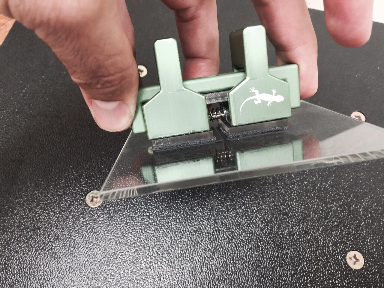
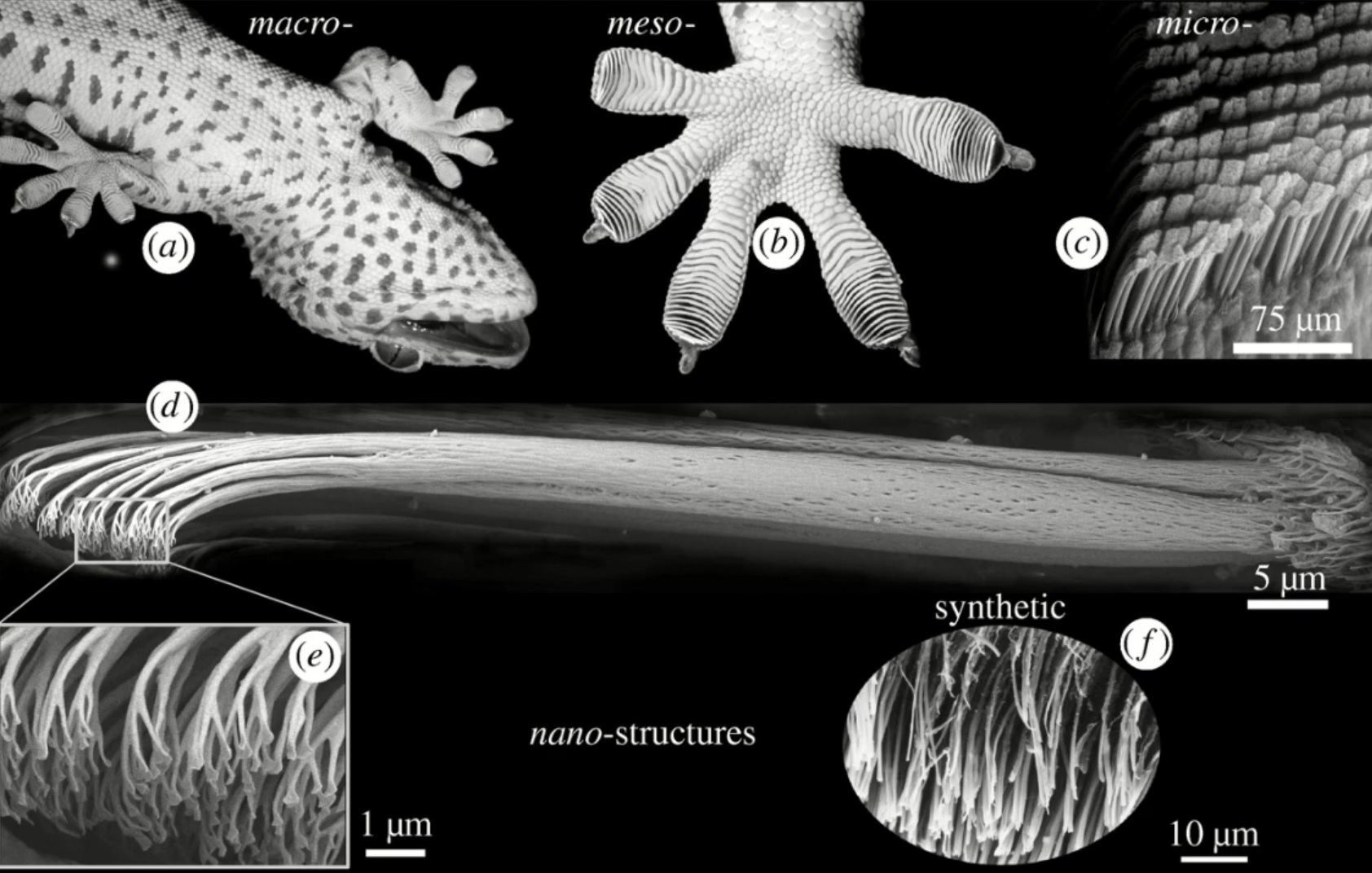
The Gecko Gripper investigation tests a gecko-adhesive gripping device that can stick on command in the microgravity environment. Geckos have specialized hairs on their feet, known as setae, that allow them to stick to vertical surfaces and their stickiness does not wear over repeated use. The use of this type of technology is hoped to enable many new capabilities such as robotic crawlers that could grip to spacecraft exteriors, manipulator systems capable of catching and releasing objects, and sensor mounts capable of working on any surface.
Gecko adhesives, like the animals themselves, make use of microscopic angled hairs to stick to surfaces using Van Der Waals forces. In the device, adhesion can be turned on and off through a slight sliding motion due to the geometry of the microstructure. The gripper can be used for thousands of cycles without loosing its effectiveness and no marks, residue, fibers or damage is left on the surface.
The Gecko Gripper experiment flies three grippers in three sizes each with two gecko adhesive pads in opposition to one another. Springs between the two pads allow the operators to prepare the the device for gripping by squeezing the pads together. The pads are touched to the surface with less than a Kilogram-force of pressure.
Once gripped to a surface, the gripper can tolerate loads and moments in all directions up to 10 Kilograms. The gripper can remain in place indefinitely and, to release, the pads are squeezed back together to pull the device away from the surface.
Testing on ISS will be compared to tests completed in a gravity environment to learn more about the physics and mechanisms of gecko adhesive which will be useful in the design of scaled-up systems for use in space. In-space application of large-scale gecko adhesive systems may include robotic repairs of spacecraft and orbital debris mitigation.
Additive Manufacturing Facility
The Additive Manufacturing Facility is the second 3D Printing device to fly to the International Space Station. The first 3D printer flew to ISS in 2014 for a demonstration mission known as the 3D Printing In Zero-G Technology Demonstration (3-D Printing In Zero-G) experiment. This initial deployment of a 3D printer had the objective of exploring the possibilities of 3D printing in space for application in future Space Station missions and for Deep Space flights as part of a ‘machine shop in space’ allowing for the production of spare parts and other items needed for such missions.
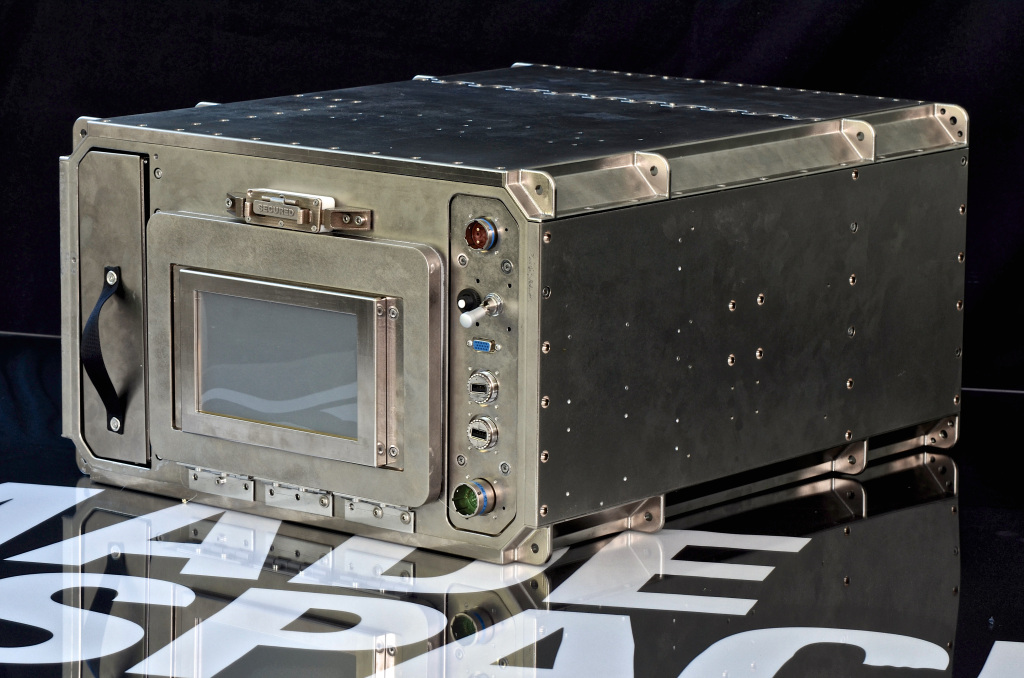
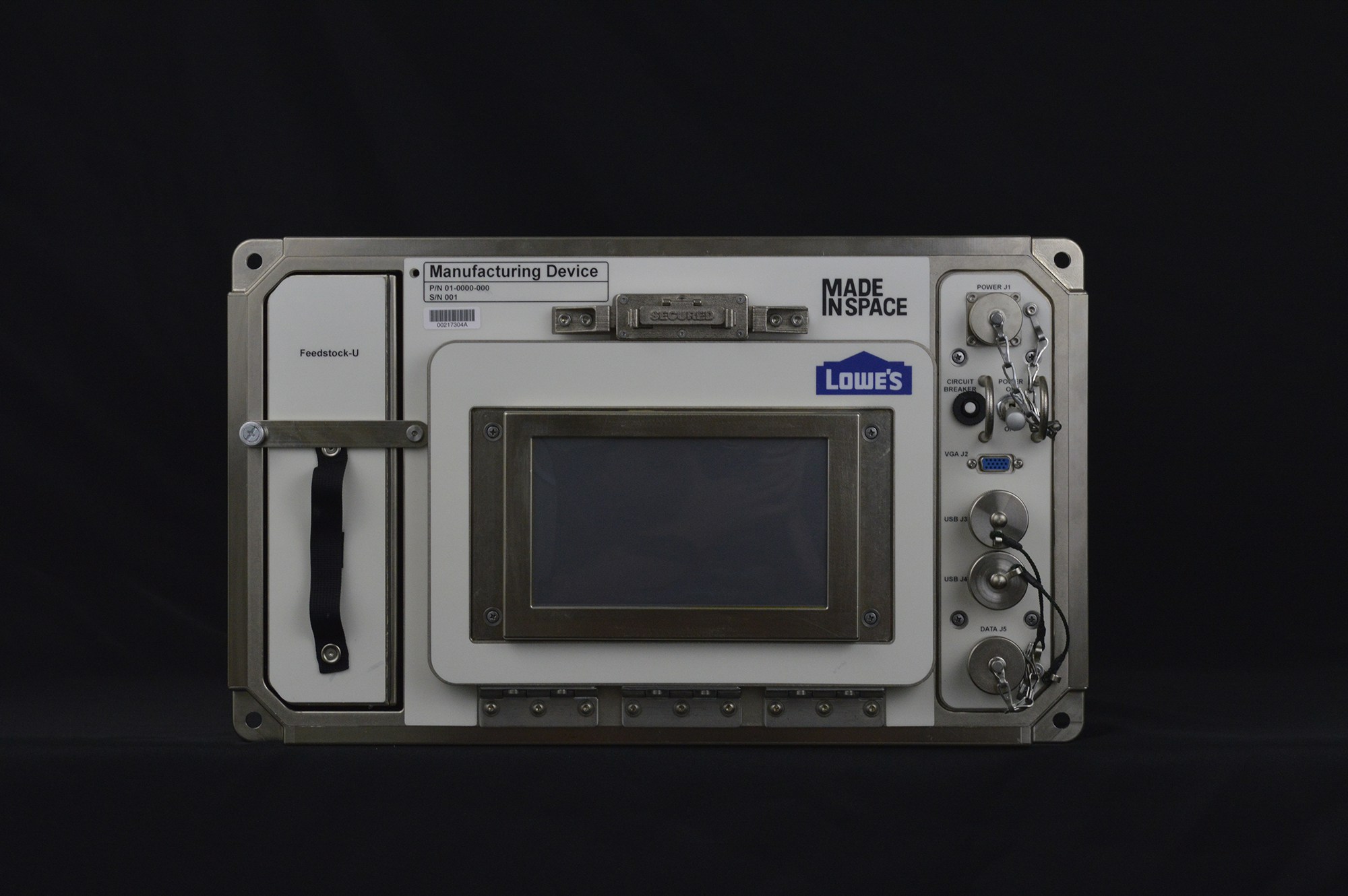
The Additive Manufacturing Facility will serve a more operational character, allowing components of experiments or systems to be produced on ISS, using a wide variety of space-rated composites, thermopolymers including engineered plastics. AMF is a permanent manufacturing facility for ISS, about twice the size of its predecessor and was also built by Made In Space.
AMF is installed in the mid-deck locker of an Express Rack and offers a print volume of 18 by 14 by 10 centimeters. Supported materials are ABS, HDPE, PEI/PC.
3D printing, also called additive manufacturing, is the process of making a three-dimensional object of almost any shape through additive processes in which successive layers of material are laid down under computer control to generate the precise shape of the programmed model. Originating in the 1980s, 3D printing has made major advancements and is now available for virtually any material from plastics, over metal to ceramics. 3D printing technologies find many applications in industry and consumer level 3D printers are available as well.
In space flight, 3D printing has shown an increasing importance. One of the companies using 3D printing as an integral part of manufacturing is SpaceX. The SpaceX SuperDraco engine is the first fully 3D printed rocket engine featuring an inconel nozzle. A number of other components of SpaceX spacecraft can also be 3D printed as tested in various ground demonstrations.
The benefits of an operational 3D capability in space are enormous which prompted NASA to begin exploring the technology for application aboard the International Space Station. Partnering with Made in Space, NASA tested a 3D printer using relatively low-temperature plastic feedstock on ISS to learn valuable lessons before establishing an “on-demand machine shop in space, a critical enabling component for deep-space crewed missions and in-space manufacturing.”
ARTE

Advanced Research Thermal Passive Exchange (ARTE) examines the performance of a passive, low-weight heat pipe to increase the heat transfer capability of materials. Thermal Control Systems such as heat pipes transporting heat from components including electronics are essential in a spacecraft’s design to efficiently transport heat to colder areas or cool down heated equipment. Axially Grooved Heat Pipes are a new technology which could reduce the weight of thermal systems while also increasing their efficiency.
Heat pipes make use of of phase change to transport heat and capillary pressure to transport mass – wherein one end of the heat pipe is the evaporator in which fluid in contact with a hot surface evaporates and then travels to the other end given its higher pressure than the vapor at the other, colder end known as the condenser. At the condenser, the vapor releases its latent heat and condenses into its fluid phase, flowing back to the evaporator due to capillary forces to repeat the process. To increase capillary action, several grooves are created within the heat pipe.
The ARTE experiment deploys 20-centimeter long Axially Grooved Heat Pipes filled with mixtures like pentane-isohexane (5%wt) and self-rewetting fluids (water-butanol) to the Space Station to undergo testing along a temperature range of 10 to 100°C. The use of low-risk fluids makes this investigation compatible with future crewed spacecraft.
The grooves are responsible for creating capillary pressure which can be considered the driving force behind the device. With grooves, the return of the liquid phase to the condenser is faster and dry out phenomena are avoided. The design of the grooves is carefully chosen based on different factors including capillary pressure, pressure losses in micro-channels and pressure losses in the vapor phase.
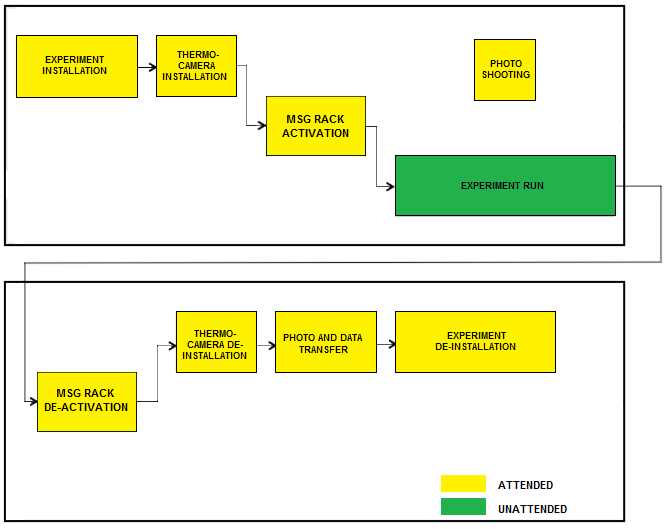
The ARTE experiment is run in the Microgravity Science Glovebox and uses a high-resolution infrared camera to deliver imagery of the heat flow within the heat pipes. Four heat pipes are part of the initial test run with at least two tests performed with each pipe.
Miniature Exercise Device

The Miniature Exercise Device, MED-2, is completing a demonstration mission to ISS to test a compact device hosting robotic actuators providing motion and resistance for crew workout sessions in the limited space available aboard spacecraft taking crews to distant targets.
Exercise is a crucial part of daily life during a long stay in microgravity as a countermeasures to muscle and bone mass loss occurring during space missions. Devices used for exercise aboard the International Space Station are rather balky and heavy pieces of equipment, not suitable for the confined space of spacecraft of the future, capable of traveling to destinations beyond Earth Orbit.
The MED-2 device demonstrates robotic technology to provide the motion and resistance needed for crew exercise. The primary goal is to test the functionality of the actuator within the system in a microgravity environment. MED-2 is a one-degree of freedom system allowing exercise using constant load, progressive loads and non-linear load. Testing onboard ISS will use instrumentation installed on the device as well as the subjective feelings of crew members testing the system in space.
MARROW
The MARROW study, known by its full name Bone Marrow Adipose Reaction: Red Or White?, looks at the effect of microgravity on the human bone marrow. It is known that prolonged exposure to microgravity, just like long bed rest on Earth, has a negative effect on bone marrow and the production of blood cells. The extent of this effect and possible recovery are of interest in space research and for application on Earth.
Blood-producing cells of the bone marrow share the confined space within the bone with fat cells which are known to grow at the expense of blood-producing cells during prolonged bed rest. Accumulation of fat cells may directly impact blood cell production and the bone marrow may also provide an explanation for abnormalities in red and white blood cells observed in zero gravity.
The MARROW study aims to measure fat changes in the bone marrow before and after space flight. Also, the investigation looks at specific changes to red and white blood cells over the course of a mission.
Vascular Echo
Cardiac and Vessel Structure and Function with Long-Duration Space Flight and Recovery (Vascular Echo) studies changes in blood vessels and the heart while crew members are in space, looking at changes in the arteries when completing long-duration space missions as a stiffening in arterial walls has been observed in astronauts returning from space, similar to a process occurring as part of aging.
Changes in size and elastic properties of blood vessels have been seen in space flight. These changes might be related to the removal of the effects of gravity on the blood pressure and the energy expenditure required to complete typical tasks as part of routine operations.
Long-term effects of arterial changes can lead to cardiovascular health consequences. Study of the processes and potential countermeasures for this phenomenon is relevant for future interplanetary exploration as well as on Earth where lifestyles have changed to make the population more susceptible to this type of issue.
Airway Monitoring

This study looks at the occurrence and indicators of airway inflammation in ISS crew members as the result of dust particles present aboard the Space Station. The experiment uses ultra-sensitive gas analyzers to study exhaled air to assess the health impacts related to dust, especially for longer duration missions for which crew members have to be self-sufficient in atmospheric maintenance and the treatment of potential health conditions.
Airway inflammation will be assessed by measuring exhaled nitric oxide. This type of diagnostic may also find application on Earth for the monitoring of asthma or other inflammatory airway diseases.
REBR
REBR, the Re-Entry Breakup Recorder, records data regarding the thermal, acceleration, rotational and other stresses the vehicle experiences during its destructive re-entry process. This data is used to improve Re-Entry Simulation Models that show inaccuracies for the peak heating environment of re-entry. REBR has a mass of about 4 kilograms and is 31-centimeters in diameter.
The REBR design consists of a sensor suite composed of a GPS receiver, temperature sensors, accelerometers and rate gyros, a pressure sensor, electronics, a commercially-available Iridium modem, a combination GPS/Iridium antenna, and batteries. The data that is acquired is stored inside the REBR memory and after entry, when the device is free falling towards Earth, it makes contact with the Iridium Satellite Fleet – making a ‘call’ home to transmit acquired information.
“The REBR is designed to be released from the reentering host vehicle during the breakup process, to fly free and reach a subsonic, free-fall velocity at about 18 km altitude, from where it will make an Iridium satellite call to ‘phone home’ its recorded data before it, too, impacts the Earth. Recovery of the device is not required,” said ESA’s Charlotte Beskow, Deputy ATV Program Head.
REBRs have flown on several previous ATV and HTV Missions. Data acquired by Re-Entry Data Recorders can be used to improve future space vehicle design, satellite reentry predictions and space debris.
.
20 Flock-2e Prime Satellites
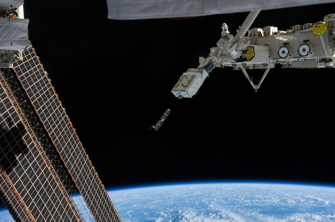
Flock 1 & 2 is a satellite constellation of CubeSats dedicated to Earth Observations using a fleet of small satellites to generate high-resolution images of Earth achieving resolutions of three to five meters. The operational constellation began deployment in 2014 and uses a combination of shorter and longer lived orbits being launched from the International Space Station and different orbital launch vehicles.
The satellites are designed, developed, manufactured and operated by Planet Labs based in San Francisco that markets the Earth Observation data products to a range of customers for a variety of applications.
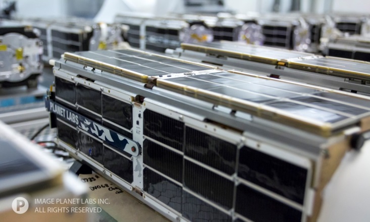
The Flock 2 spacecraft are based on the three-unit CubeSat specification having a launch mass of about 5 Kilograms and being 100mm × 100mm × 340mm in size featuring body mounted solar panels and two deployable solar arrays with three panels each using triangular advanced solar cells.
The solar arrays are spring-loaded and deployed by burn-wires once the satellites are released into their independent orbits. Flock spacecraft contain Lithium-Ion batteries that provide power to the various systems. A power distribution unit delivers power to all subsystems. The load bearing satellite structure consists of three skeleton plates, with L rails along each corner edge. Laser etched side panels are used for the Flock satellites.
Attitude data is provided by three-axis magnetometers to accomplish three-axis stabilization via a reaction wheel system and magnetic torquers for momentum management. Fine pointing data is provided by a Star Camera. Flock 1 satellites use a single-board computer to control all spacecraft and payload functions with a watchdog board able to reboot the flight computer in the event of errors or radiation related upsets.

The satellites use an X-Band system for the downlink of acquired images and systems telemetry at data rates of up to 120Mbit/s. Primary command uplink is done via S-Band, although a low-speed Telemetry and Command System operating in the UHF band is also available and in use for early commissioning operations and as a backup.
The main payload of each satellite is an optical telescope of unknown specifications to acquire high-resolution images of Earth. The telescope has an aperture diameter of 90mm and is protected by an aperture cover that is deployed via springs. The optical axis is down the central axis of the satellite to achieve a maximum focal length.
According to Planet Labs, the Flock-2e-Prime batch of satellites is comprised of standard RGB full-color imaging satellites, satellites supporting RGB and near-infrared imaging, and five technology demonstration satellites testing systems for the next generation of CubeSats.
The Flock satellites, also known as Doves, are going through constant modifications and improvements, even within a group of satellites, not all are necessarily identical. Variations that have been introduced include the use of improved detectors and infrared filters.
Lemur 2 Satellites
The Lemur-2 satellites are 3-Unit CubeSats built and operated by NanoSatisfi, now named Spire Global, to establish a constellation of small, inexpensive satellites in operation for a number of purposes such as Earth observation, maritime monitoring, communications, meteorology and science. The first Lemur satellite launched in 2014 and carried a series of technical demonstration payloads plus two Earth observation systems operating in the visible and infrared wavelength ranges.
The Lemur-2 satellites carry two different payloads, SENSE, dedicated to maritime monitoring, and STRATOS for atmospheric measurements.
SENSE consists of an AIS receiver that can record signals sent by the Automatic Identification System of ships using the VHF frequency. The Automatic Identification System is used by sea vessels that send and receive VHF messages containing identification, position, course and speed information to allow the monitoring of vessel movements and collision avoidance as well as alerting in the event of sudden speed changes.
These signals can be transmitted from ship-to-ship and ship-to-shore to allow the monitoring of a local area, but deploying space-based AIS terminals allows a broad coverage and data relay to ground stations for monitoring of large sea areas. However, due to the large footprint of satellites, overlapping and signal collisions become a problem, especially for frequented traffic routes, requiring a steady improvement in reception technology to separate the different signals.
STRATOS makes use of GPS occultation measurements to determine temperature, pressure and humidity profiles of Earth’s atmosphere for application in operational meteorology.
The instrument consists of GPS receivers to be able to track the signals of several MEO satellites and measure the time delay and bend angle of signals that travel through the atmosphere located in the line of sight of the two spacecraft. These phase delay measurements due to refraction by the atmosphere can be made from the satellite altitude to very close to the surface leading to precise information on the properties of the atmosphere at an accurate vertical resolution.