Deimos 2 Satellite Overview
Deimos-2 is a Spanish Earth Observation Satellite as a follow-on to Deimos-1 that launched in 2009. The satellite was designed and developed by Satrec Initiative, an Elecnor company, for operator Deimos to acquire high-resolution images of Earth for a variety of purposes.
Deimos-2 uses a multispectral pushbroom imager to capture images on a 12-Kilometer swath achieving a resolution of one meter for panchromatic images and four meters in the visible and near infrared spectral range.
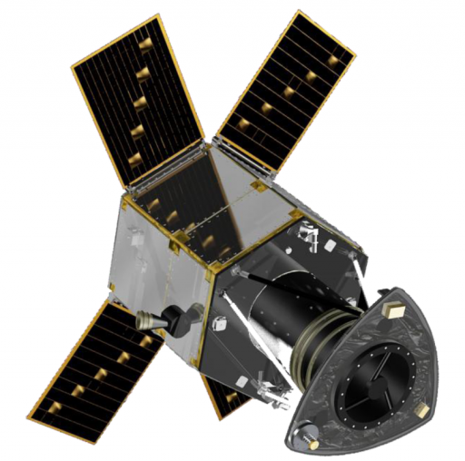
The satellite is based on the SI-300 spacecraft bus that is a small-class platform capable of hosting Earth observation and science payloads. Features of the platform are hall-effect thrusters for orbit control and maintenance, agile and accurate pointing for precise imaging and a dual-redundant systems architecture. Deimos-2 is 1.5 by 1.95 meters in size with a mass of ~310 Kilograms.
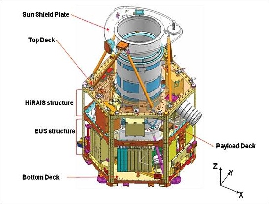
The satellite bus consists of two decks and an upper sunshield. The decks and the side panels facilitate the satellite electronics. Longerons and and rails are making up the bus structure frame. Carbon Fiber Reinforced Plastic struts are used to hold the sun shield at the baffle of the main payload, the High Resolution Advanced Imaging System that is installed on the internal deck structure.
Four solar panels are attached to the sides of the satellite and deploy shortly after launch. Each array consists of six individual panels that each contain 26 cells. The solar arrays generate 450 Watts of power. The four solar arrays provide electrical power to a triple-redundant Battery Charging Regulator that manages the sate of charge of a Li-Ion battery that has been designed for ten-year mission duration. A Primary Power Conditioning Module and a Secondary Power Conditioning Module provide the satellite’s power bus.
A regulated 28-Volt power bus is converted into unregulated buses at 15, 12 and 5 Volts. These voltages are distributed by the Primary & Secondary Power Distribution Modules. The EPS is a stable system that includes Safety and Separation Module to save and maintain battery voltage levels.
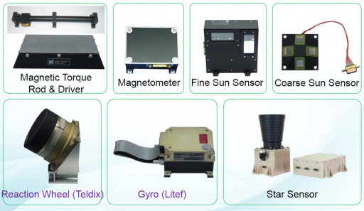
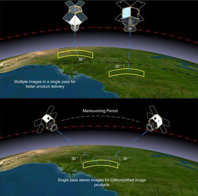
Deimos-2 is three-axis stabilized and its Attitude and Orbit Control Subsystem provides satellite pointing capability for single-strip, multi-strip and single-pass stereo imaging. Five reaction wheels are used for attitude control along with four Fiber Optic Gyros. Attitude data is provided by Star Trackers for fine-pointing and magnetometers and sun sensors for coarse pointing in safe and acquisition mode. Deimos-2 has a pointing accuracy of 0.03 degrees on all axes. A key-feature of the satellite is a high-agility to allow fast body-pointing of up to 45 degrees off nadir, however, during nominal operations off-nadir angles of up to 30° will be used.
A Hall Effect Propulsion System is used for orbit maintenance and orbit adjustments. It uses electric propulsion utilizing Xenon gas and a microwave cathode.
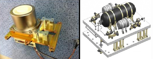
The HEPS system consists of a XFU (Xenon Fuel Unit), THU (Thruster Head Unit), PPU (Power Processing Unit) and the MCU (Microwave Cathode Unit). The XFU holds about two Kilograms of Xenon fuel that is held at a pressure of 150 bar. Via pressure valves and orifices, Xenon is allowed to flow into two smaller tanks, each at 3 bar for the anode and cathode. The thruster head includes magnets for ion motion detection while the PPU provides the different voltages for the HEPS system to accelerate generated Xenon ions to high velocity for ejection. The HEPS provides 7 Millinewtons of thrust consuming about 300 Watts of power.
The Command and Data Handling System handles all telecommands sent to the satellite and collects all telemetry from the satellite’s subsystems. Two CAN networks with data rates of 500kbit/s are using a series of Interface Boards to connect all satellite modules to the networks. The Interface Boards are in charge of formatting telemetry data and handling messages received from the main computer.
The Actuator Interface Board controls the speed of the reaction wheels and provides a speed feedback to the computers.
Gyro telemetry is provided by a Gyro Interface Board while a Primary and Secondary Power Interface Board controls the Power Modules. Attitude sensor data is provided by a Sensor Interface Board while the Thermal Interface Board takes temperature readings for heater actuation. X-Band antenna driving units control the communications system and a dedicated HEPS control board drives the Orbital Control System.
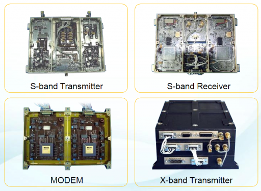
Two Telemetry and Telecommand Boards are operated in hot-redundancy to perform all telecommand decoding and telemetry encoding directly interfacing with the S-Band system that is used for command uplink and telemetry downlink. The On-Board Computer is the central processing unit of the vehicle that communicates with all modules through the CAN network. All telemetry data from the various subsystems is processed and recorded. All telecommands are handled and executed by the system to control all the satellite’s functions. The computers run flight software using the VxWorks operating system. Onboard data storage us accomplished by Solid State Recorder Units with a total capacity of 256 Gbit. The data system compresses, encrypts and encodes the payload data in real time during transmission using a lossless compression scheme and CCSDS encoding.
The satellite is equipped with an S-Band communications system for command uplink and telemetry downlink. Payload Data is downlinked via a high-speed X-Band terminal that achieves data rates of 160Mbit/s using QPSK modulation. The system uses a one-axis steerable antenna that can be moved by +/-90 degrees to track a ground station and transmit a focused radio frequency beam.
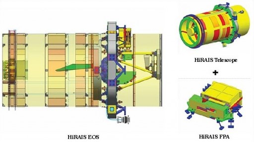
The main instrument of the satellite is the High Resolution Advanced Imaging System that provides Earth imagery with a ground resolution of 1 meter for panchromatic images and 4 meters for multispectral imagers. The imager covers a ground swath of 12 Kilometers.
HiRAIS was designed and developed by SI (Satrec Initiative) and Elecnor Deimos and has successfully flown on previous missions. The payload consists of three main elements – the electro-optical subsystem, the solid state recorder and the Image Transmission Unit.
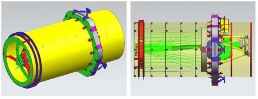
The payload features a Korsch-type telescope with a five-mirror design with a field of view of 1.2 degrees. The main mirror of the satellite is 41.5 centimeters in diameter. Three folding mirrors are used to create a total focal length of 5.7 meters. A Flat Mirror reflects the light onto the Focal Plane Assembly. The mirrors are made from Zerodur that provides high-thermal stability. The telescope structure consists of Reinforced Carbon Fiber for a high thermal stability and a feedback heating system is used to keep the telescope components in perfect alignment featuring accurate thermostats and heaters along with passive heat-rejection systems.
Located on the Focal Plane Assembly is a pushbroom-type Charged Coupled Device that acts as detector and provides an analog signal that is converted into a 10-bit digital data stream that is processed by the Onboard Computer for storage and eventual downlink.
The detector operates as a pushbroom imager with time-delayed integration.
The imaging payload covers a panchromatic channel (450-900nm) and four multispectral channels – Blue (420-510nm), Green (510-580nm), Red (600-720nm) and Near Infrared (760-890nm). Multispectral resolution is 4 meters and the sharpened-PAN mode achieves ground resolutions of up to 0.75 meters.
During its nominal operations, the satellite spends the majority of its sunlit orbit portion in a sun-pointing attitude to charge its batteries. In eclipse, the satellite is pointing nadir to minimize the use of payload heaters. When in Earth Imaging mode, the satellite normally uses off-nadir angles of +/-30 degrees to acquire images of targets. For special targets of opportunity, off-nadir angles of up to 45 degrees are acceptable.
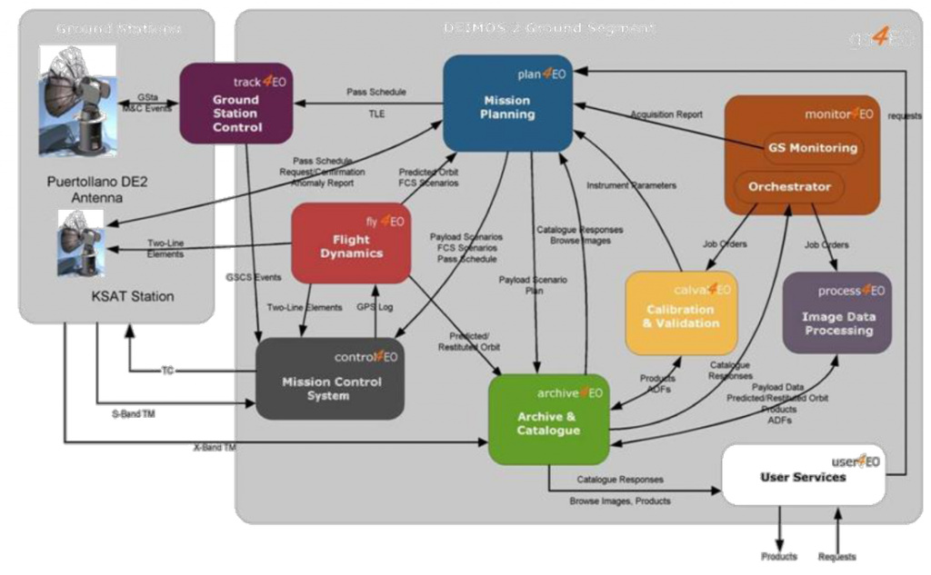
Deimos-2 can operate in single strip imaging, multi-pointing imaging of close targets, single-pass stereo imaging by along-track pitch maneuvers. For imagery downlink, the satellite acquires an attitude to have its X-Band antenna facing the Ground Station and using the gimbal mechanism to track the station. The main ground station for Deimos-2 is Puertollano (Spain) with a 10-meter dish. The Svalbard station in Norway is used when needed.
Deimos-2 uses the gs4EO ground system architecture and CAMP Tool for mission planning (Capacity Analysis and Mission Planning) to implement a high-degree of automation into mission planning, spacecraft commanding, resource management and data processing.
Ground Segment