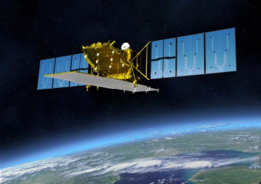
ALOS-2 – Satellite Overview
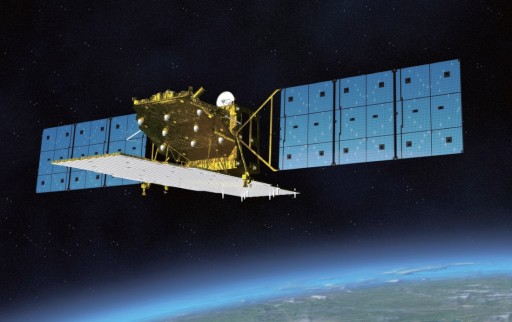
ALOS-2 – the Advanced Land Observation Satellite 2 is a radar Earth Observation satellite operated by the Japanese Aerospace Exploration Agency to acquire high-resolution radar imagery of Earth for cartography, regional observation, resource management, disaster management and scientific purposes. The satellite is the follow-on project to ALOS-1 that was launched in January 2006 and operated for five years until experiencing a complete power loss in 2011.
ALOS-2 will enhance the capabilities of the previously flown SAR payload on ALOS and provide an increased resolution, faster revisit times, and observation at high incidence angles.
ALOS-2 was manufactured by Mitsubishi Electric Corporation under contract by JAXA to facilitate two primary instruments – the PALSAR-2 Phased Array L-Band Synthetic Aperture Radar, a Compact Infrared Camera – and a small AIS (Automatic Identification System) terminal.
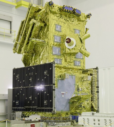
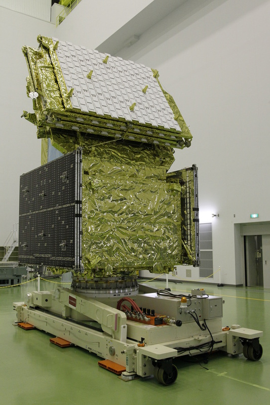
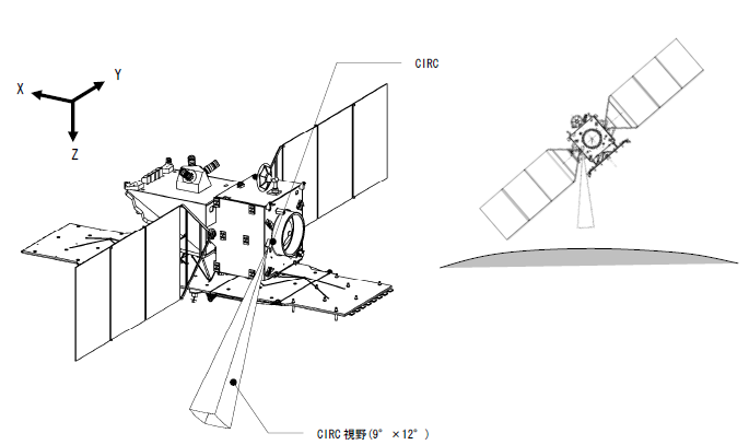
The spacecraft weighs 2,120 Kilograms and is 9.9 by 16.5 by 3.7 meters in size when fully deployed on orbit. ALOS-2 uses a modular approach consisting of a bus module, the large L-Band SAR antenna, a payload electronics unit and two small payload modules for the Compact Infrared Camera and the Space Based Automatic Identification System Experiment 2.
ALOS-2 is equipped with two three-panel solar arrays using triple-junction gallium-arsenide solar cells for a total output power of 5,200 Watts at the end of the mission. A dedicated avionics unit is responsible for the conditioning of the satellite’s main power bus and of the regulation of the state of charge of the onboard batteries.
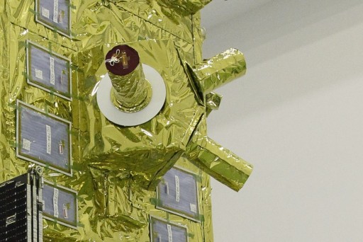
Spacecraft thermal control is accomplished using a combination of passive thermal control featuring blankets and multilayer insulation and active thermal control using thermally conductive coldplate assemblies, heat pipes and radiators installed on the space-facing side of the spacecraft. Heaters are used to maintain operating temperatures of electronics equipment when needed.
Attitude control and actuation is accomplished by a suite of attitude sensors and a combination of thrusters, reaction wheels and magnetic torquers.
ALOS-2 is equipped with a Star Tracker Assembly consisting of three optical heads and corresponding analog and digital electronic units building a redundant system.
Two of the star trackers are used at a time to acquire imagery of the sky that is analyzed by a software algorithm that compares the acquired star pattern with a catalog to precisely determine the spacecraft’s orientation in space. Each star tracker has a field of view of 8 by 8 degrees and uses a CCD detector operating at 1Hz. Overall, the star tracker assembly weighs 40 Kilograms and has a peak power consumption of 150 Watts.
In addition to its Star Trackers that have a maximum acquisition rate of 0.1 deg/s, ALOS-2 uses an Inertial Reference Unit for three-axis attitude and rate sensing that ensures control at higher rates e.g. during initial attitude acquisition. Additionally, an Earth Sensor and Coarse Sun Sensors are installed on the satellite to ensure good Sun/Earth-pointing in spacecraft safe mode.
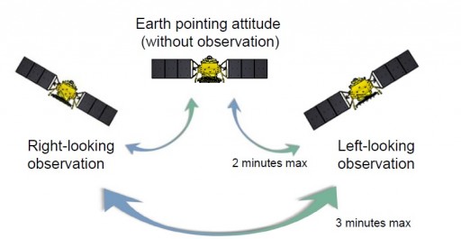
Attitude actuation is provided by a propulsive attitude control system featuring a series of 1-Newton Hydrazine monopropellant thrusters as well as a Reaction Wheel Assembly and magnetic torquers that are used in spacecraft safe mode and during RWA momentum dumps. For the operation of the SAR payload, ALOS-2 has to be capable of rapid and accurate attitude maneuvers about its roll axis in order to achieve side-looking of its SAR antenna. Body pointing in roll for SAR observation is possible from +30 to -30 degrees.
To minimize the time required for attitude maneuvers, ALOS-2 employs a specially developed Reaction Wheels Assembly consisting of five wheels. Four wheels are used as a standard Reaction Wheel Assembly that ensures redundancy in three-axis spacecraft pointing. The fifth wheel is aligned with the roll axis to maximize maneuverability for quick roll maneuvers taking 109 seconds from nadir-looking to +/-30 degrees side-looking or 159 seconds for a slew from left to right.
Overall, the Reaction Control Wheels can deliver 0.9Nm of output torque and a maximum momentum of 40 Nms at 3200 rpm with a maximum roll rate of 0.7 degrees per second.
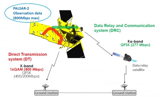
The ALOS-2 mission principle requires a rapid data availability after acquisition and the spacecraft employs a twofold communications architecture with an X-Band system for payload data downlink to the ground and a Ka-Band terminal for data transfer to a data relay satellite in Geostationary Orbit.
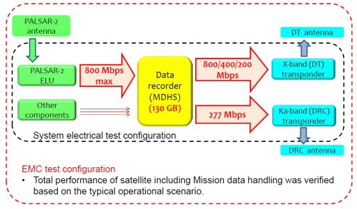
ALOS-2 uses a Mission Data Handling System that processes and stores data acquired by the payloads as well as systems telemetry in a 130GB memory ahead of data downlink.
To meet the high data downlink volume requirement, ALOS-2 employs an innovative XMOD System, Multi-mode High Speed Modulator that is capable of achieving a maximum data rate of 800Mbit/s using Quadrature Amplitude Modulation (16QAM) and Quadrature Phase Shift Keying to remain compatible with existing ground stations. The system consists of a baseband module featuring the necessary Serializers&Deserializers, Digital to Analog Converters, a Temperature Compensated Crystal Oscillator and SRAM-based FPGA.
The X-Band carrier is generated by a load oscillator while the RF module is in charge of quadrature modulation on the signals generated by the baseband module followed by signal amplification. ALOS-2 uses two X-Band antenna arrays.
The XMOD system has a mass of four Kilograms and fits into an envelope of 30 by 12 by 19 centimeters. It is internally redundant and supports data rates of 200, 400 and 800Mbit/s at frequency bandwidths of 240 and 123 MHz.
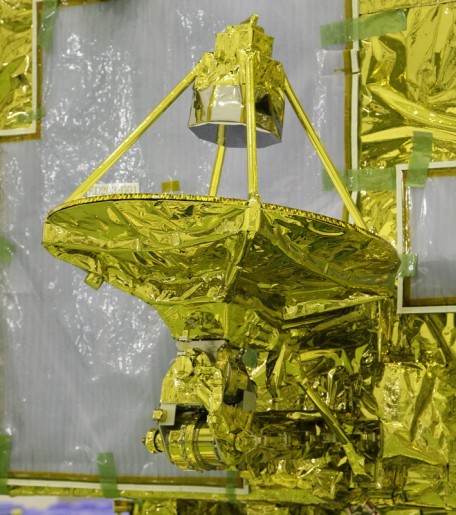
On the space-facing deck of the spacecraft resides the gimbaled Ka-Band antenna of the satellite that is used to transmit data to the Kodama Data Relay Test Satellite using QPSK Modulation at a data rate of up to 277 Mbit/s.
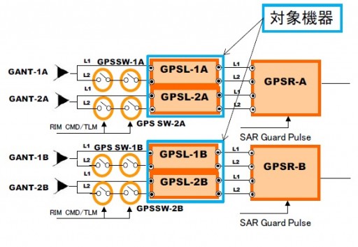
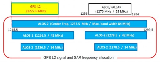
For its precise orbit control scheme, ALOS-2 is equipped with a Spaceborne GPS receiver that provides precise orbit data to the vehicle for orbit monitoring and maneuver planning. The dual-frequency GPS receiver uses both, signals in the L1 and L2 bands, however, the L-Band radar frequency used by ALOS-2 overlaps with the L2 navigation signal – requiring the L2 input to be switched off during SAR observations.
The requirement of an orbit determination accurate to ten meters is far surpassed by the GPS receiver installed on ALOS-2 achieving accurate measurements of 0.5 to 0.8 meters in L2 Loss Mode and better than 0.2 meters using L1 and L2 signals.
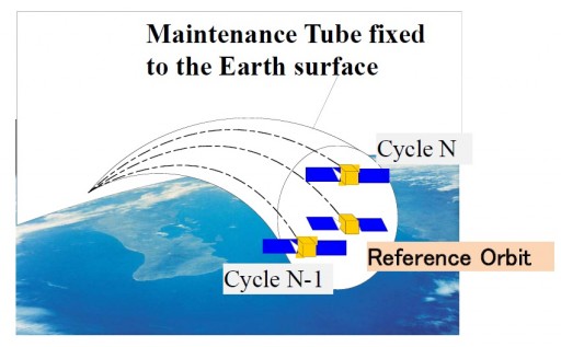
ALOS-2 operates in a Near-Circular Sub-Recurrent Sun-Synchronous Orbit at an altitude of 628 Kilometers and an inclination of 97.4 degrees creating a revisit time of 14 days. The mission includes a strict orbit maintenance scheme to ensure a high coherence of interferometry measurements. Therefore, the ALOS-2 satellite has to be kept within a 500-meter tube around a precisely calculated reference orbit.
Precise GPS measurements, detailed perturbation modeling and repeat cycle modeling are employed for orbit determination, prediction and orbit maintenance maneuver design. To keep ALOS-2 within its orbital corridor, an average of one in-plane maneuver every five days for drag-makeup and one out of plane burn every 176 days will be needed with in-plane burns as frequent as every 1.5 days during periods of high solar activity.
Because of the high maneuver frequency, ALOS-2 uses an autonomous orbit maintenance system that coordinates maneuvers autonomously without the need of maneuver command design on the ground. Mission planners will allocate several maneuver slots per day in accordance with planned SAR observations to prevent orbit maintenance from impacting satellite operations.
From these orbital maneuver slots, the autonomous system then chooses a slot when a maneuver is required – as calculated by using GPS parameters for orbit determination and the reference mean element data for orbit error calculation. Once a slot is selected, the system automatically computes the required delta-v, time of ignition and spacecraft attitude before developing maneuver commands ready for execution by the spacecraft.
A number of safeguards within the software and the ALOS control system and attitude control system software prevent erroneous burns of long duration that would put the satellite in an incorrect orbit.
PALSAR Payload
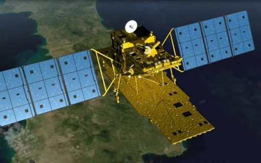
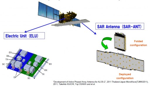
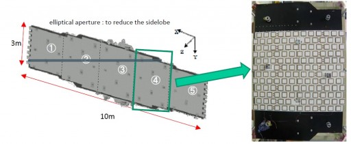
The main instrument of the ALOS-2 spacecraft is PALSAR-2 – the Phased Array L-Band Synthetic Aperture Radar-2 that uses Active Phased Array Antenna technology. Radar satellites bounce radar signals off the ground and record the weak echo signal to deduce radar reflectiveness of sites on the ground which differs between the various types of vegetation, water bodies and man-made structures. Overall, the system consists of two main components: the antenna subsystem and the electric unit. The antenna is 2.9 meters wide and 9.9 meters long weighing 548 Kilograms.
The PALSAR-2 instrument supports observations in stripmap mode as well as spotlight and ScanSAR modes to achieve a ground resolution of one to three meters. Beam steering in range and azimuth and side-looking observations and a coverage of wide incidence angles of 8 to 70° allows the instrument to cover a wide area on the ground of up to 2,320 Kilometers to support high revisit times.
The SAR antenna consists of five panels featuring a total of 1,080 active radiation elements driven by 180 Transmit and Receive Modules (TRM) that provide the transmit signal and process the received signal. When operating at full power, the SAR power requires 5,100 Watts of power, but the payload can also be operated in a partial-aperture mode that only uses panels 2,3 and 4 requiring 3,300W of power.
The radar signals transmitted and received by the antenna are conditioned and processed in the electric unit that consists of an exciter, transmitter, receiver, digital processor and systems controller. The exciter generates the chirp signals that are then up / down-modulated. The radar has a selectable center frequency of 1236.5, 1257.5 or 1278.5 MHz that can be stretched to bandwidths of 84, 42, 28 or 14 MHz. PALSAR operates at Pulse Repetition Frequencies of 1500 to 3000 Hz and supports different polarization modes.
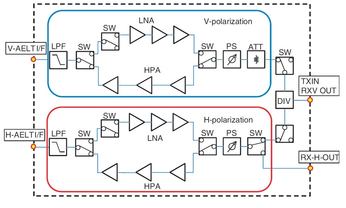
The Transmit Receive Modules provide Tx and Rx gain and phase control. The systems can support rapid beam steering, beam shaping and polarization selection – it is a dual-polarized antenna that can transmit in a selected polarization and receive in both polarizations simultaneously. A Compact Polarimetry Mode allows simultaneous transmission of H and V polarization to achieve a linear polarization.
Each TRM weighs about 0.4kg and measures 20 by 11 by 1.5 centimeters in size. The system features High Power Amplifiers using Gallium Nitride High Electron Mobility Transistors to provide an output with low-loss and high-power characteristics achieving an output power of 34 Watts at an efficiency of 35%.
In receiving mode, the weak echo signal is amplified by Low Noise Amplifiers in the electronics and summed up using the same network as the transmit system. After filtering, the receive signal is digitized, formatted and recorded. Signal compression is accomplished via Block Adaptive Quantization using a compression up to 4-bit.
TRM Design
PALSAR is capable of operating in three different modes – the conventional stripmap mode, spotlight mode and ScanSAR Operation. In stripmap mode, the payload can be operated on an ultra-fine, a high-sensitivity and in fine mode to achieve different resolutions and ground swath widths.
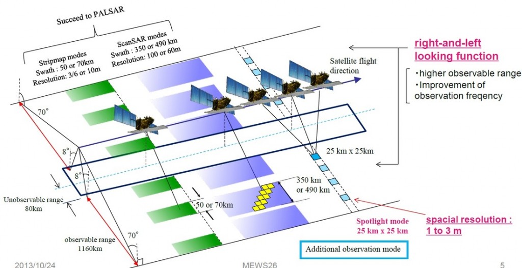
In the fine stripmap mode, PALSAR covers a 70-Kilometer ground swath operating at one of its three selectable frequencies and a bandwidth of 28MHz. Fine stripmap achieves a ground resolution of 10 meters providing a data volume of 400Mbit/s. In this mode of operation, the instrument supports single polarization, dual polarization, full polarization (quad polarization) and the experimental Compact Polarization.
The High Sensitivity mode also supports these different polarization modes and all three frequencies, but operates the radar at a bandwidth of 42MHz covering a 50-Kilometer swath with a maximum ground resolution of 6 meters creating a data volume of 800Mbit/s.
In the ultra-fine stripmap mode, PALSAR can only operate in single and dual polarization mode and only supports its center frequency of 1257.5 MHz. Covering a 50-Kilometer swath and operating at a bandwidth of 84MHz, the ultra-fine mode reaches ground resolutions of 3 meters.
The spotlight mode uses single-polarization imaging of ground tiles of 25 by 25 Kilometers operating the radar at the center frequency o 1257.5 MHz and a bandwidth of 84MHz. This high-resolution mode achieves a ground resolution of 3 meters in range and 1 meter in azimuth.
ScanSAR allows the instrument to cover a wide swath of 350 Kilometers with a resolution of 100 meters in single and dual polarization mode, and a selectable frequency. Operated in this mode, PALSAR operates at 14 MHz and delivers a data volume of 400Mbit/s.
The Full Polarization mode switches between horizontal and vertical polarizations at the Pulse Repetition Interval which doubles the time of repeat pulses and reduces the available swath from 70 to 30 Kilometers.
Calibration of the SAR payload is accomplished using internal calibration to track the performance of the radar over time and compare it to pre-flight calibrations. External calibration uses ground targets of known properties to provide and end-to-end calibration of the system.
Compact Infrared Camera
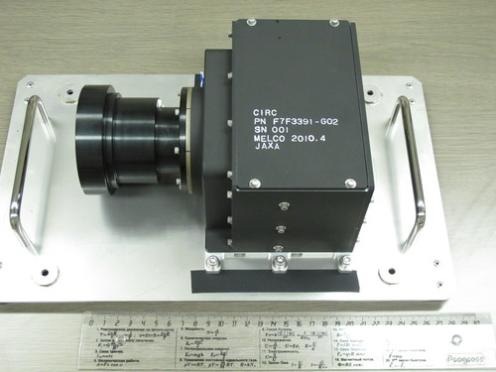
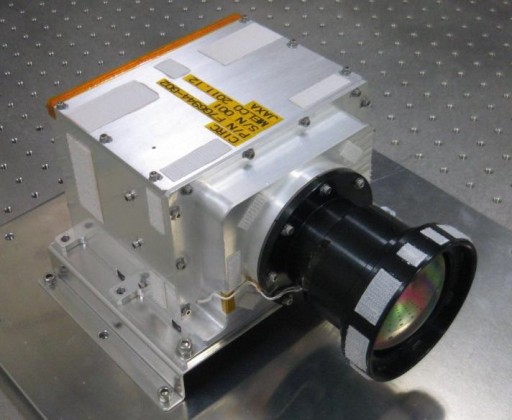
The Compact Infrared Camera CIRC is a small payload developed by MELCO under contract from JAXA using COTS (Commercial off the Shelf) components to build a compact infrared imager for deployment on several spacecraft to create an operational wildfire detection capability. CIRC is making its first flight on ALOS-2 and will also be deployed on the International Space Station.
CIRC weighs just under 3 Kilograms and is 18 by 11 by 23 centimeters in size. Because of its compact size, low power consumption and low data rates, the instrument is ideal for deployment as secondary payload on a number of spacecraft.
The infrared imager has an aperture diameter of 6.5 and a focal length of 7.8 centimeters and uses athermal optics to avoid defocus caused by temperature changes of the optics using a chalcogenide glass and a series of germanium lenses and windows. The instrument has an operational range of -15 to +50°.
CIRC uses a shutterless design approach to simplify and downsize the instrument, however, this eliminated a calibration source as a closed shutter can be used for instrument calibration. Instead, stray light correction is accomplished as a function of instrument temperature measured by a sensor and complementing ground testing using black body imaging.
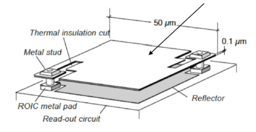
To comply with its low power and small size requirements, CIRC could not be outfitted with a cooling system that is usually employed for infrared detectors. Therefore, microbolometer array that does not require cooling was selected as detector. Each pixel on the array consists of several layers including an infrared absorbing material and a reflector underneath it that directs IR radiation that passes through the absorber back to the absorbing layer to ensure a near complete absorption. As IR radiation strikes the detector, the absorbing material is heated and changes its electrical resistance which can be measured via electrodes connected to each microbolometer and processed into an intensity read-out.
CIRC uses a Silicon-On-Insulator SOI diode Focal Plane Array with a size of 640 by 480 pixels and pixel sizes of 25 micrometers. The detector has low-noise characteristics and a high sensitivity in the spectral range of 8-12 micrometers. The instrument has a field of view of 12 by 9 degrees and a dynamic range of 180 to 400K. The nominal exposure time is set at 33 milliseconds.
At an altitude of 600 Kilometers, the instrument achieves a spatial resolution of 200 meters which is sufficient for the detection and monitoring of wildfires, the observation of volcanoes and the assessment of ‘hot spots’ created by cities or human activity.
Space based Automatic Identification System Experiment 2
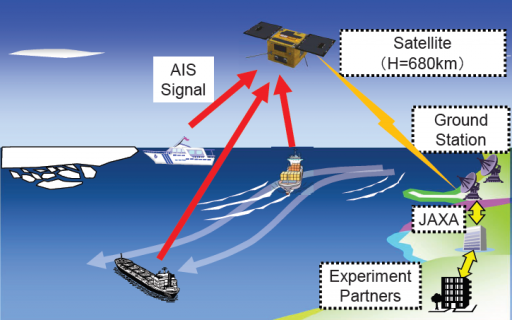
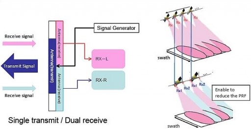
ALOS-2 also carries the SPAISE2 payload, the Space based Automatic Identification System Experiment 2 which is a technical demonstration payload featuring a four-channel signal reception capability. The Automatic Identification System is used by sea vessels that send and receive VHF messages containing identification, position, course and speed information to allow the monitoring of vessel movements and collision avoidance as well as alerting in the event of sudden speed changes. These signals can be transmitted from ship-to-ship and ship-to-shore to allow the monitoring of a local area, but deploying space-based AIS terminals allows a broad coverage and data relay to ground stations for monitoring of large sea areas.
However, due to the large footprint of satellites, overlapping and signal collisions become a problem, especially for frequented traffic routes. SPAISE evaluates a space-based AIS reception system and investigates the potential of the system with partners that regularly use AIS data.
SPAISE-2 weighs 14 Kilograms and is 105 by 80 by 80 centimeters in size operating at a sample rate of 76.8 kHz. Its main antenna is a cross dipole antenna. The system operates at frequencies of 161.975, 162.025, 156.775 and 156.825 MHz. The payload will demonstrate digital sampling followed by ground processing as an operational architecture for AIS-S applications.
As an experiment, AIS data can be combined with the SAR images obtained by ALOS-2 to create maps and other data products that may be of use when tracking traffic at sea.
ALOS Application
Data provided by ALOS-2 will be used for a variety of scientific and other purposes. An annual global mosaic will be used to monitor deforestation and generate global forest maps and wetland change maps. Using biomass classification methods, ALOS data will be used to create a global biomass map to track changes over time.
Crop monitoring and land use classification will also be supported by data from the SAR payload that can also provide valuable data for the analysis of surface deformation due to earthquakes, volcanic activity, subsidence and landslides. PolSAR data can be used to generate soil moisture maps while stacking and correcting of SAR imagery will yield Digital Elevation Models. When overflying the polar regions, the SAR payload can be used to monitor sea ice and glacier movements.
A data turnaround of under 60 minutes in the event of disasters will provide valuable data for the assessment of the extent of a natural disaster and help personnel respond to natural catastrophes.