FormoSat-5 Satellite
FormoSat-5 is a Taiwanese Remote Sensing Satellite representing the first fully indigenous development of a remote sensing instrument at the National Space Organization (NSPO) of Taiwan under its Second Phase Space Program initiated in 2004 to establish new capabilities and independent developments for the exploitation of space. The satellite is a follow-on to FormoSat-2 launched back in 2004 and decommissioned in August 2016, closing a critical gap in Earth-imaging capabilities for Taiwan.
Under the FormoSat-5 project, NSPO aimed to acquire new technologies in the area of spacecraft platforms, instruments, ground support equipment and flight software. To further domestic space capabilities, NSPO worked with the Instrument Technology Research Center (ITRC) under supervision by Taiwan’s National Science Council to develop a fully domestic space mission without relying on prime contractors from the U.S. and Europe which had been the case for the first FormoSat missions.

NSPO is responsible for the FormoSat-5 platform, the ground segment, systems engineering, and program management while the craft’s primary instrument was developed jointly by NSPO and ITRC. Most satellite components were sourced from Taiwanese Industry with only few exceptions; launch services were outsourced to SpaceX as an outside contractor.
FormoSat-5 had a long road to the launch pad, starting development in 2005 which ended up being a lengthy process with several delays and challenges that had to be overcome. The mission’s launch contract was awarded to SpaceX in 2010 with the initial expectation of launching in 2013 on a Falcon 1e rocket. With Falcon 1 being abandoned, the project moved on to the much more powerful Falcon 9 rocket and continued drifting, initially to 2015 and then to 2016 due to payload related issues and eventually into 2017 for a combination of payload readiness and delays on the SpaceX side.
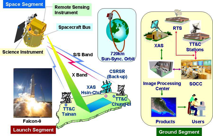
High-resolution panchromatic and multi-band color imagery collected by FormoSat-5 will be used for a variety of applications including state governance, national security, technological diplomacy, academic research, environmental monitoring, disaster prevention and relief, and international humanitarian relief. In addition to its high-resolution imaging instrument, FormoSat-5 hosts an Advanced Ionospheric Probe to deliver scientific measurements from the ionosphere for space weather and geophysical research.
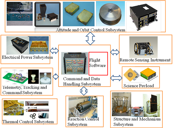
Design work on the FormoSat-5 mission had the broader scope of developing an NSPO heritage spacecraft platform capable of extending into the future and facilitating more powerful remote sensing payloads with greater needs in the areas of electrical power, thermal control, pointing accuracy and data volume. To that end, NSPO developed the structure, avionics subsystems and flight software from a clean sheet. Additionally, to remain cost effective, the platform was designed using Commercial Off The Shelf components that were put through customized space qualification processes to find a suitable compromise between low-cost components and in-space reliability.
Satellite Platform
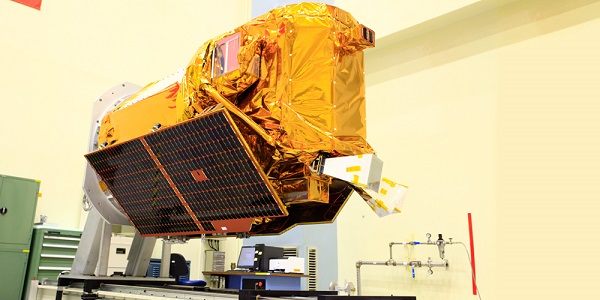
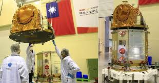
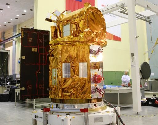
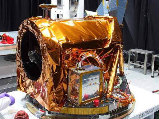
The FormoSat-5 satellite is octagonal in shape, standing 2.8 meters tall and measuring 1.6 meters in diameter with a launch mass of 475 Kilograms. The three-axis stabilized spacecraft has a life expectancy of at least five years and will support flexible imaging operations with a wide field of regard of +/-45 degrees in the along and cross track directions.
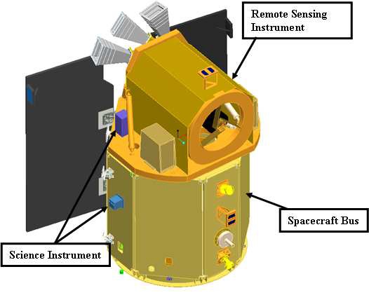
The FormoSat-5 spacecraft consists of two principal modules – the octagonal spacecraft platform and the payload module comprising the RSI imaging instrument and Star Tracker for precise attitude determination. The platform consists of an aluminum skeleton as the load-carrying structure with a base plate facilitating the launch vehicle adapter and propulsion system and a forward panel providing structural support to the payload. The platform itself is an irregular convex octagon which means there are four larger and four smaller side panels which act as the mounting surfaces for the majority of internal subsystem components and various electronics boxes.
The Electric Power System of the FormoSat-5 satellite consists of two deployable solar panels, a battery unit and a central Power Control and Distribution Unit (PCDU). Each solar panel contains 19 strings of 20 triple-junction Gallium-Arsenide solar cells in series delivering an orbit-average power of 280 Watts that is passed to the PCDU from where various redundant DC supplies are distributed across the satellite and to the battery.
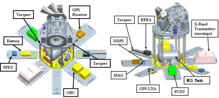
The PCDU is designed to handle over 150 FET switch outlet channels, converting the 28-Volt primary power supply to users as demanded via secondary power buses. It also controls the state of charge of the 24 Amp-hour battery that is based on small cell technology with eight in series and 16 in parallel, outputting a voltage between 21 and 35V.
Housed within the PCDU are 17 circuitry modules; a Charge Regulator conditions the raw main bus of the satellite that hosts a pair of redundant Power Modules delivering a redundant primary power bus to the satellite loads, a pair of redundant DC/DC converters conditions secondary power to the satellite loads (5.2 and 15 Volts), a dedicated Ordnance Electronics unit switches power to deployment devices and a Propulsion Electronics Unit delivers voltages for thruster actuation.
Raw power is collected from 38 solar electricity control panels and processed by the Power Relay module tasked with managing the switchover of redundant DC/DC converters, distributing secondary power and providing bus protection. Internal/External DC/DC converter pairs have their own overcurrent protection realized via latch-up current limiters controlled by the PR module’s Field Programmable Gate Array.
To avoid short circuits in the DC/DC converter sections, the module provides an under-voltage protection by switching the nominal converter to the redundant unit. The PCDU has a pair of interface units that collect housekeeping measurements from the various power components and actuate the power system based on inputs from the main flight computer.
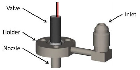
FormoSat-5 hosts a Cold Gas Propulsion System with four thrusters fed from a central Nitrogen tank installed on the bottom panel of the spacecraft structure. The Cold Gas Thruster (CGT) consists of a solenoid valve with very little leakage and broad voltage range, an 0.6mm throat diameter, 15° cone nozzle, a mechanical interface plate and the fluid interface supplying the Nitrogen gas. Each thruster assembly weighs only 43 grams and operates at a nominal thrust of 46 millinewtons at an inlet pressure of 1.5 bar, creating a specific impulse of 70.4 seconds. The thruster is designed for 1.5 million actuations and can be operated in pulses as short as 1 millisecond up to long steady state operation with a mass flow of 62mg/s.
The Cold Gas Propulsion System has a central Nitrogen tank, feeding two pairs of thrusters via a pressure regulator and isolation valves to provide redundancy in the event of a leak or valve failure on one thruster. The system will be primarily used for orbit maintenance and debris avoidance but could also be used to assist in attitude control.
The Attitude Determination and Control System for the FormoSat-5 mission was built with the stringent requirements of a precise Remote Sensing Mission, calling for a 3σ geo-location accuracy of 390 meters that takes into account orientation errors due to misalignment between the optical bench and the star tracker, and between the star tracker and the inertial reference frame used by the satellite. The geolocation requirement translates to an absolute pointing knowledge requirement of 0.012 degrees.
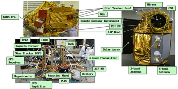
To comply with the tight pointing requirements of the mission, the mission uses a Micro-Advanced Stellar Compass (µASC) comprising three star tracker heads and four single-axis fiber optic gyros installed on the optical bench to avoid mis-alignment between bus and payload module and to limit thermal fluctuations. µASC was provided by the University of Denmark and is a fully autonomous device comprising the DTU-built star trackers and μ-FORS6U fiber optic gyros produced by Litef, a Northrop Grumman branch in Germany.

The µASC Star Tracker Unit comprises three Optical heads and a single Data Processing Unit, capturing imagery of the star-filled sky that is analyzed by an onboard algorithm to identify known stars from a large catalog and calculate the craft’s precise three-axis orientation in space. According to DTU, µASC typically operates in a dual-redundant configuration and delivers attitude solutions accurate to 2 arcseconds and supports attitude rates up to 20 degrees per second, generating 8 (nominal) to 22 measurements per second and requiring only 30 milliseconds for initial acquisition from a lost in space scenario.
The µFORS6U gyroscopes were originally envisioned for air, land and sea applications, but NSPO’s environmental tests showed they would also be suitable for application in space. µFORS6U can measure body rates up to 327.7°/s with a noise of +/-0.15° and a bias of +/-3°/hour. Because the µFORS6U product has not flown on an operational mission, the risk of two or more failures was considered and FormoSat’s flight software includes provisions for gyro-less attitude determination in which gyro data is computed numerically and fed into the typical gyro-stellar algorithm.

In addition to the µASC sensors that provide fine control in science operations, FormoSat-5 also hosts six Optical Sun Sensors and a pair of magnetometers to provide attitude determination in safe mode and data for actuation of the magnetic torque rods. Four reaction wheels represent the primary attitude actuators with three torque rods in use during safe mode control, initial de-tumble and for momentum dumps from the wheels.
The attitude actuation system achieves a pointing accuracy of 0.1 degrees and enables the spacecraft to slew up to 45 degrees in any direction (along track or cross track) for image targeting, though FormoSat-5 is not as agile as its predecessor, requiring 113 seconds to slew 45 degrees on the roll or pitch axes while yaw rates are even more sluggish at 0.12°/sec.
A pair of spaceborne GPS receivers are used to receive position information for orbit determination, geotagging of imagery and time synchronization via a Pulse Per Second Signal used to set the flight computer clock.
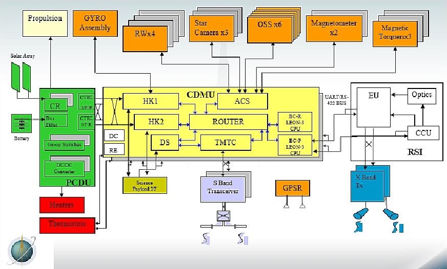
All attitude sensors and actuators interface directly with the Command and Data Management Unit (CDMU) that builds the central component of the spacecraft and is in charge of all satellite functions – executing ground commands, conditioning housekeeping telemetry and actuating all platform and payload systems.
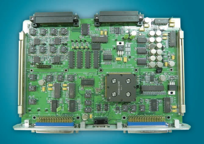
The primary spacecraft computer is a 20 MIPS Leon-3 Fault-Tolerant processor implemented on an Actel AX-2000 Field Programmable Gate Array, building a highly configurable system that includes a variety of functions including Floating Point Unit, Spacewire link, ports for CAN & UART, a clock system and a memory controller. Leon-3 operates as a 32 bit synthesisable processor and has board-level redundancy control of the other unit.
The three Spacewire interfaces from the flight computer connect with the payload, the ground support equipment (only during testing) and the Spacewire Multiplexer/Demultiplexer that acts as the spacecraft’s central data hub with ten Spacewire input/output interfaces to interconnect all satellite systems with a data rate of up to 50Mbit/s.
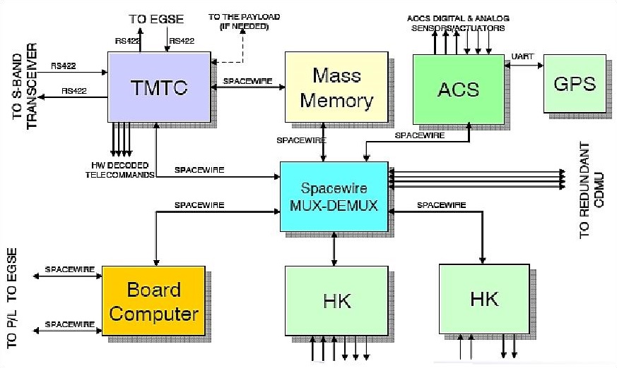
The MUX-DEMUX unit also builds the primary bridge between the functionally identical CDMUs that operate in a hot-redundancy scheme. A Reconfiguration Electronics module manages the redundancy between the two CDMUs, monitoring alarms from the prime CDMU and any irregularities to either command the prime CDMU to re-set, switch to the redundant unit or place the two CDMUs into a cross-strapped configuration until ground intervention is possible.
The Data Storage Module is used to store satellite health telemetry and science data, offering a 256 MB SDRAM memory with EDAC protection plus 3 Gbits mass storage; the science data storage capacity is 80 Gbit. The Housekeeping Modules of which there are two complete the collection of housekeeping data from all satellite subsystems and carry commands from the CDMU using analog inputs and outputs, digital inputs and outputs, and serial modules; they also communicate with the satellite’s redundant GPS modules and carry position/timing data to the onboard computer and the payload data processing system.

A dedicated Telemetry and Telecommand Module is in charge of encoding/decoding the telemetry/command data according to the ESA packet telemetry standard, interfacing with the satellite’s S-Band transceiver via a serial RS-432 bus to receive the commands sent from the ground and deliver housekeeping data for downlink with data rates of 128 kbit/s and 8 Mbit/s, respectively. It has Spacewire interfaces with the central MUX/DEMUX and the Mass Memory Unit, a backup connection to the payload that would come into play if the high-speed X-band transmitter fails, and several direct command paths to the satellite subsystems as part of a redundant data system.
The ADCS module exchanges attitude information and actuation commands with the satellite computer via the MUX/DEMUX and has digital and analog interfaces with the various sensors and actuators to manage the attitude control system.
FormoSat-5 uses S-Band for command uplink and telemetry downlink using a redundant transceiver unit while a high-speed X-Band transmitter is employed for the downlink of image data with a data rate of up to 150Mbit/s.
Instruments
The primary payload of the FormoSat-5 satellite is known a the Remote Sensing Imager, RSI – featuring a 45-centimeter telescope to collect imagery at two-meter ground resolution (black and white) and four meters for multi-spectral imagery.
The instrument was developed domestically in Taiwan with ITRC (Instrument Technology Research Center) taking the lead over an industrial consortium that included CIC (National Chip Implementation Center), CSIST (Chung-Shan Institute of Science and Technology), AIDC (Aerospace Industrial Development Corporation), CIS (CMOS Sensor Inc.), and CAMELS Vision Technologies. RSI’s development also laid the foundation for more advanced remote sensing instruments, not limited to visible imaging, to be developed for more complex missions in the future, potentially with international involvement.
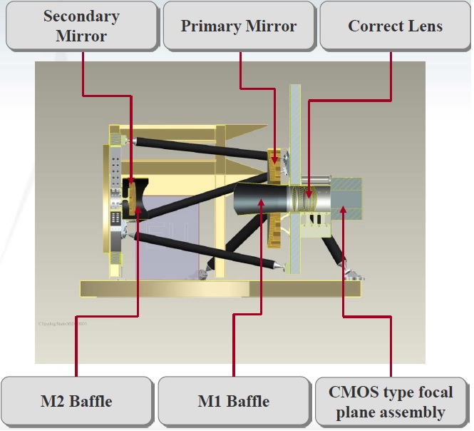

RSI is a pushbroom imager comprising a Cassegrain Telescope and a multi-band line detector array operated in a Time Delay Integration scheme; per the pushbroom concept, RSI sweeps out image swaths on the ground utilizing the satellite’s orbital motion. Generalized Cassegrain-type telescopes make use of two mirrors placed on the optical axis of the telescope – a concave M1 primary mirror and an on-axis convex M2 mirror that focuses the light onto the Focal Plane Assembly.
The instrument employs a structure made of Carbon Fiber Reinforced Polymer chosen for its load-carrying capabilities and favorable thermal properties to keep the optical components aligned. RSI has an aperture diameter of 45 centimeters and has optical baffles for both of its mirrors to reject stray light, a correct lens is used to remove optical disturbances and focus the image onto the focal plane assembly.
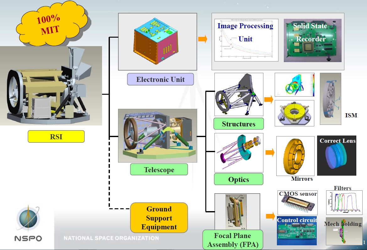
The RSI Focal Plane Assembly comprises the CMOS (Complementary Metal Oxide Semiconductor) line detectors, bandpass filters, control & read-out electronics, and the housing structure.
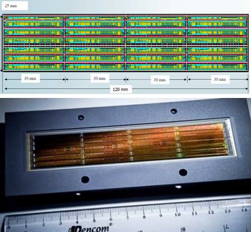
The detector features five lines (corresponding to five imaging bands) with 12,000 pixels (10µm pixel pitch) for the panchromatic imager and 6,000 pixels in each of the four multi-spectral lines (20µm pixel pitch), allowing the panchromatic channel to operate at 2x resolution.
All channels cover an identical swath of 24 Kilometers and are read-out according to a time delay integration scheme to compensate for satellite motion and allow overlaying imagery to be created. The detector, stitching four system-on-chip devices, is 12 by 2.3 centimeters in size.
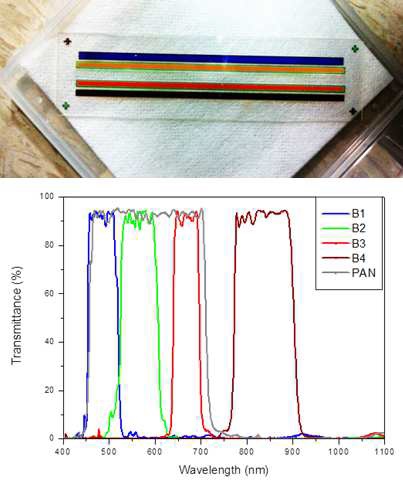
The five-band filter was designed in-house at UMC (United Microelectronics Corporation) and exceeds required expectations.

The instrument’s panchromatic coverage stretches from 450 to 700 nanometers and the multi-band channels are as follows: B1 Blue (445-515nm), B2 Green (525-595nm), B3 Red (630-690nm) and B4 Near-Infrared (695-965nm). RSI delivers 12-bit image depth and employs a real-time processing technique with Discrete Wavelet Transfer and Bit Plane Encoder to compress the high-volume raw data onboard the spacecraft before downlink.
RSI is supported by a purpose-built Electronics Unit that handles instrument control and data processing, accepting a raw data rate of 480 Mbps from the detector read-out electronics and processing for storage on a 128 Gbit solid-state device. The EU also conditions the payload data downlink, outputting a data rate of 150 Mbps. It is capable of autonomous file management and isolation of bad memory.
The Advanced Ionospheric Probe (AIP) was developed at National Central University, Jhongli City as an all-in one plasma sensor with high sampling rate to deliver measurements of ionospheric plasma density, particle energy & speed and ambient magnetic field at exceptionally high spatial resolution.
AIP’s primary objective is taking a detailed census of the particle environment and creating global ionospheric maps in the upper F-region over an extended period of time to bring out seasonal variations and study space weather phenomena. One specialized area of research pursued by the instrument is the influence of plate tectonics on the ionosphere which may provide a way of predicting imminent earthquakes.
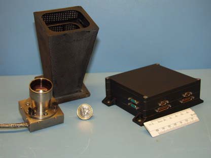
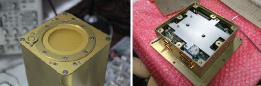
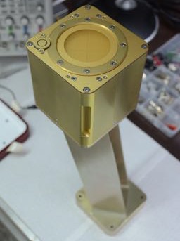
AIP incorporates several in-situ ion and plasma sensors: PLP (Planar Langmuir Probe), RPA (Retarding Potential Analyzer), an IT (Ion Trap), and IDM (Ion Drift Meter). All AIP sensors are housed within a sensor head installed on a 35-centimeter stand that places the sensors into the incoming particle flow from the spacecraft ram direction with a Payload Electronics Unit facilitated on the main satellite body.
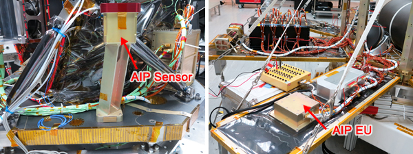

The Sensor Head is 10 by 10 by 10 centimeters in size and weighs 580 grams, using an aluminum housing and offering a 56-degree field of view directed toward the satellite’s direction of travel.
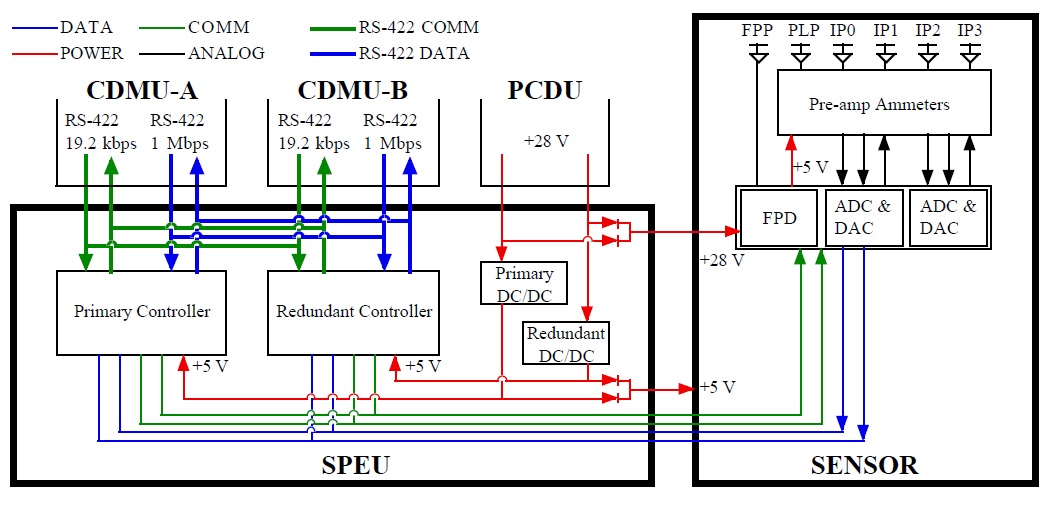
It sits on an aluminum stand of 14 by 13 by 35 centimeters with a mass of 880 grams and interfaces with a 18 x 18 x 6 cm Payload Electronics Unit that weighs in at 1.95 Kilograms, creating a total instrument mass of 4.5 Kilograms (including the wire harness). AIP requires a power of 5 Watts and delivers telemetry at 19.2 kbps while the science data output does not exceed 1 Mbps. Single-event latch-up protection is provided within the instrument’s electronics and AIP has an expected operational life of at least two years.
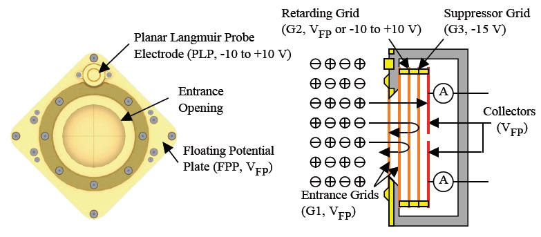
Langmuir probes can determine electron temperature, electron densities and the electric potential of a plasma through a simple measurement method involving one or more electrodes inserted into the plasma surrounding the spacecraft. The electrodes are either operated at a fixed bias or sweep through a range of voltages to measure the current in the electrode system to determine the plasma charge density that is proportional to the electron currents. AIP uses a single Langmuir Probe that sweeps through -10 to +10 Volts and records the associated current-voltage curves whose slope will yield the desired electron temperature measurement.
The Retarding Potential Analyzer (RPA) is a multi-grid analyzer designed to provide in-situ ion density and energy measurements using electrically biased grids placed between a 5-centimeter aperture and a quadrant collector where the absorbed ion current is measured. The first grid placed in the RPA aperture is a retarding grid connected to a floating potential device that holds the grid at ground to avoid the interior electric field from affecting the incoming stream of ions.
The second grid is the primary retarding grid which stets an energy barrier for incoming ions by sweeping through -10 to +10 Volts, selecting the incoming ion energy band (rejecting ions below the selected energy band). When operating in the Ion Trap Mode, AIP will hold this grid at the floating potential in order to not repel any incoming ions to allow the entire ion flux to be directed to the collector for measurement.
G3, the third grid, acts as a suppressor grid biased at -15 Volts to prevent secondary and photo electrons created within the collector from leaving the instrument which could bias the current measurement and cause a positive distortion to the collector current. All three RPA grids consist of gold-coated stainless steel coated with a 0.11 mm wire diameter.
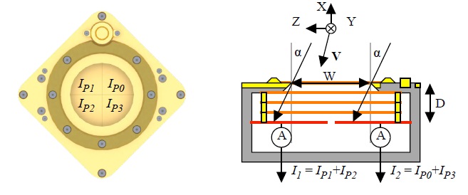
All four metal plates of the quadrant collector are maintained at the floating potential and interconnected to an ammeter for current measurements to create I-V curves from the collector measurement and retarding grid voltage which can yield ion temperature, composition and velocity.
In the IDM (Ion Drift Meter) mode, the G1 and G2 grids are both maintained at floating potential, but each of the detector plates is connected to an individual current meter so that the arrival angle of incoming ions can be measured through the current difference of the adjacent detector plates. Typically, AIP will operate in each of its four modes for one second (PLP, RPA, IT & IDM), creating a four-second measurement cycle for the desired ionospheric parameters. Sampling rates can be adjusted as needed between the nominal sampling rate of 128 samples per second up to a burst mode taking 8,192 samples per second.