
VENµS Satellite Overview
VENµS – the Vegetation and Environment Monitoring New Micro-Satellite – is a joint -French-Israeli satellite project that combines a scientific Earth observation mission using a high-resolution super-spectral imager with a technology demonstration of a Hall Effect Thruster System for major orbital changes and orbit maintenance in the Low Earth Orbit regime.
The project had a fairly long road to the launch pad with an initial agreement between the French Space Agency CNES and the Israel Space Agency signed in 2005 that called for launch as early as 2008. Under the program, Israel was expected to spend around $20 million while France contributed $13 million. Israel Aircraft Industries is in charge of building the satellite, Elop Electro-Optics Industries Ltd. was tasked with development of the multi-spectral imaging payload and IAI provides the Mission Control Ground Segment while France is responsible for technical assistance, project management and the science aspect of the mission (data processing, analysis, archiving and distribution). Israel’s Rafael provided the Hall Effect Thruster to be tested by the mission.

The scientific mission of VENµS utilizes a multi-spectral imaging instrument covering twelve spectral channels in the visible and infrared wavelengths, capturing imagery across a 27-Kilometer ground swath at a resolution of five meters. The mission was originally envisioned to be a research demonstrator for Europe’s Copernicus Program, but significant delays ended up pushing the mission until well after the first space segment components of Copernicus started operations.
VENµS will provide data for ecosystem monitoring, capturing imagery of 50 sites that are representative of the world’s inland and coastal ecosystems every two days in all of the craft’s spectral bands, providing information on vegetation cover and health and helping in the development for new automated extraction methods to turn satellite data into biosystem parameters. Data from the mission will help researchers follow the water and carbon cycles and deliver additional data on the interface between land masses and the atmosphere for the development of atmospheric models. VENµS will also contribute to agricultural management, continental hydrology and coastal oceanography.

VENµS is expected to carry out its primary science mission from a Sun Synchronous Orbit 720 Kilometers in altitude. The satellite will remain in this orbit for the first two and a half years of its mission before starting the Hall-Effect Thruster demonstration that will see the satellite maneuver down into a 410-Kilometer Sun Synchronous Orbit, requiring the satellite to not only change its altitude but also reduce the inclination by over two degrees to remain in a true Sun Synchronous Orbit with constant illumination. Once reaching 410 Kilometers, VENµS will attempt to maintain the orbit for as long as possible and continue its imaging mission at higher ground resolution as a result of the closer distance to Earth.
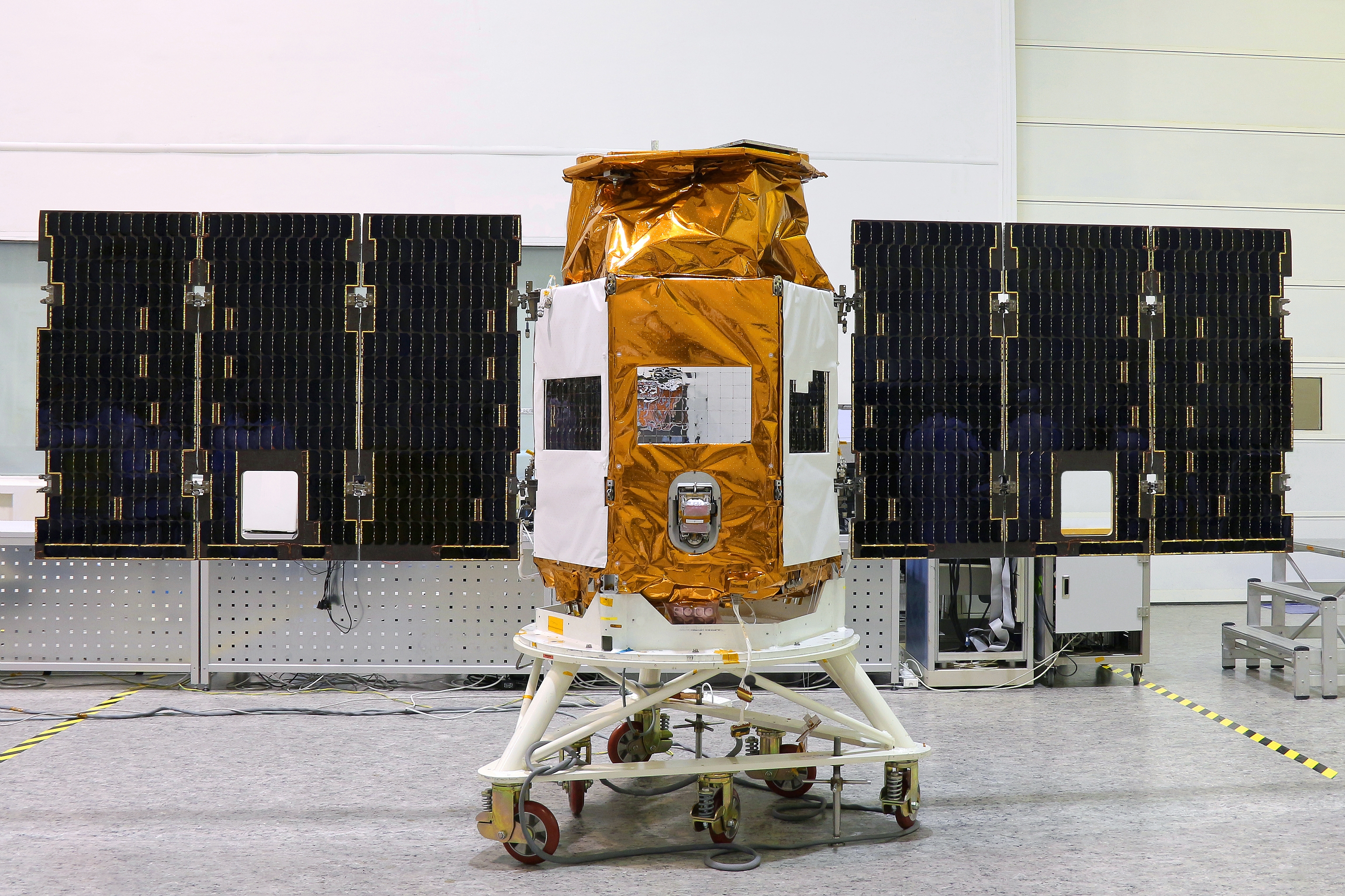
The VENµS satellite uses an Improved Multi Purpose Satellite Platform (IMPS) that was designed and developed by IAI and Rafael (Advanced Defense Systems Ltd.). The platform is also known as OptSat-2000 bus with previous flight heritage within Israel’s semi-classified Ofeq image and radar reconnaissance program. VENµS has a launch mass of 264 Kilograms and uses an octagonal structure measuring 1.2 meters in diameter and standing 1.6 meters tall when in its stowed launch configuration, spanning 4.4 meters with its solar arrays extended.
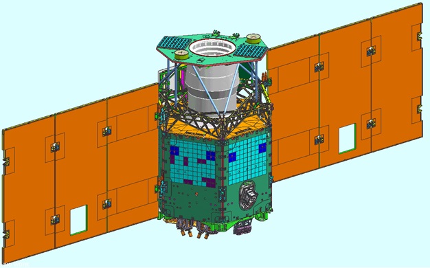
The satellite hosts two three-panel solar arrays which, coupled with a single body-mounted panel, creating a large solar array capable of generating 800 Watts of power fed to a redundant Power Conditioning Unit which distributes power to all satellite subsystems and regulates the charge of a Li-Ion battery unit. Attitude determination is accomplished with a pair of Star Trackers, dual Coarse Sun Sensors, redundant three-axis magnetometers and an inertial measurement system while actuation is accomplished with four Reaction Wheels (a one-failure tolerant design) while three magnetic torquers provide momentum for wheel unloading and attitude control in safe mode.The Attitude Control System provides quick slew capability, enabling off-nadir imaging at up to +/-30 degrees, giving the satellite a field of regard of 720 Kilograms.
VENµS hosts redundant S-Band transceivers for command uplink and housekeeping telemetry; payload data is stored in redundant 30 GB memory units and downlinked to the ground using a dual channel X-Band transmitter reaching a data rate of 2 x 155 Mbit/s.
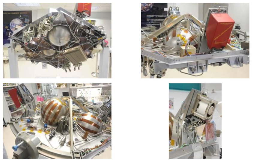
The VENµS satellite hosts two propulsion modules – one traditional chemical propulsion system for initial orbit adjustments during the primary imaging mission and an experimental Hall Effect Thruster System (IHET) that will come into play for the technology demonstration mission.
The traditional propulsion system hosts a central tank holding 7 Kilograms of Hydrazine monopropellant fed to four 1-Newton thrusters that employ the catalytic decomposition of Hydrazine over a metallic catalyst bed to create high-pressure combustion gas. A second bank of four thrusters is available in case the primary system has to be isolated in the event of a malfunction.
IHET is the Israeli Hall Effect Thruster, developed by Rafael Ltd., Israel for application as propulsion system on the country’s future satellites, enabling multi-orbit missions, autonomous orbit maintenance and drag compensation.

The goal of the technology demonstration mission carried out by VENµS is achieving space qualification of the thruster design via a demonstration of its capability to generate meaningful delta-v for orbit changes as well as long-term operation for orbit maintenance.
Electric propulsion has the major advantage of being much more efficient than traditional chemical propulsion in terms of specific impulse, meaning the satellite requires less propellant mass to achieve a target change in velocity. However, ion thrusters only deliver a fraction of the thrust of chemical rockets and all-electric satellites need much longer to reach their orbital destination, creating a trade-off.
The IHET System comprises a pair of thruster modules and a central tank holding 16 Kilograms of Xenon propellant stored at 16 bar. Other equipment part of IHET includes pressure regulators, latch valves, flow controllers, control units and a Power Processing Unit.
Xenon flows from the tank into the system through a Central Latch Valve into a Pressure Regulating Assembly that outputs a gas pressure of 1.9 bar, fed to a common Digital Xenon Flow Controller that delivers a controlled mass flow rate to the active thruster which is selected by the Thruster Selection Unit within the central Power Processing Module.
Xenon propellant is directed into the thruster via a Thruster Valve Module comprising an Anode and Cathode Valve Module which are controlled based on the required thruster operation and prevent a loss of gas in the event of a power outage.
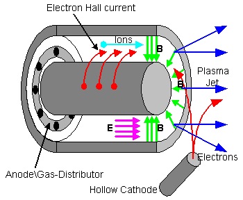
The Sequence Control Unit is tasked with providing the cathode and anode voltages to the operational thruster and actuate all valves within the propellant regulation system and the thrusters themselves – it operates in a closed loop with the Digital Xenon Flow Controller to regulate the Xenon flow rate in unison with the thruster voltages. Xenon is directed into the thruster through a gas distributor that resides within the anode board.
The hollow cathode emits free electrons that then enter a spiraling motion within the thruster channel by means of an applied magnetic field. Xenon atoms entering the thruster collide with the electrons to generate charged ions which are then accelerated out of the thruster channel – delivering an impulse to the satellite. The plasma jet from the thruster is neutralized with additional electrons that do not enter the thruster channel in order to manage the total spacecraft potential.
The IHET thrusters will be operated under an autonomous control scheme that calculates the power availability on an orbit-to-orbit basis and actuates the thrusters accordingly. For the initial maneuver from the 720km orbit to an altitude of 410 Kilometers, the thrusters will be operated to slow the satellite down over the course of what is expected to be a six-to-ten-month sequence. Once at the new operational orbital altitude, the IHET system will transition to a new operational mode to autonomously compensate for drag encountered in the upper atmosphere and keep the satellite at a constant altitude for at least one year.
All in all, each of the IHET thrusters will undergo around 2,500+ duty cycles over the course of the mission and accumulate over 1,000 operating hours. IHET is expected to generate a thrust of over 15 millinewtons and reach a specific impulse of more than 1,300 seconds for an input power of 300 Watts.
The primary payload of the VENµS mission is the VENµS Superspectral Camera VSSC – a 12-channel imaging system capable of collecting spectral imagery for ecosystem assessments and other remote sensing parameters. CNES is responsible for providing design specifications for the camera system, built by ELOp. It uses heritage from the MSRS (Multi-Spectral high Resolution Sensor) design of ELOp and OHB Systems that was envisioned to fly on a mission for the European Union but never lifted off the drawing board.
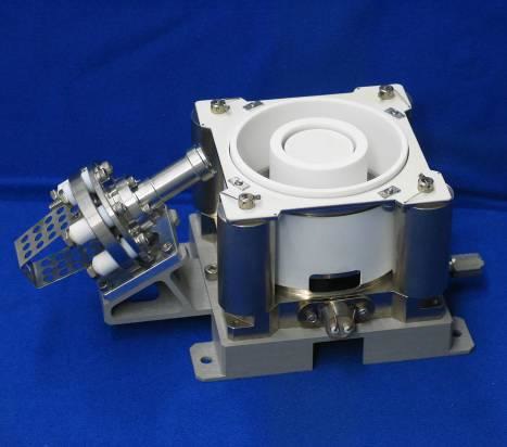
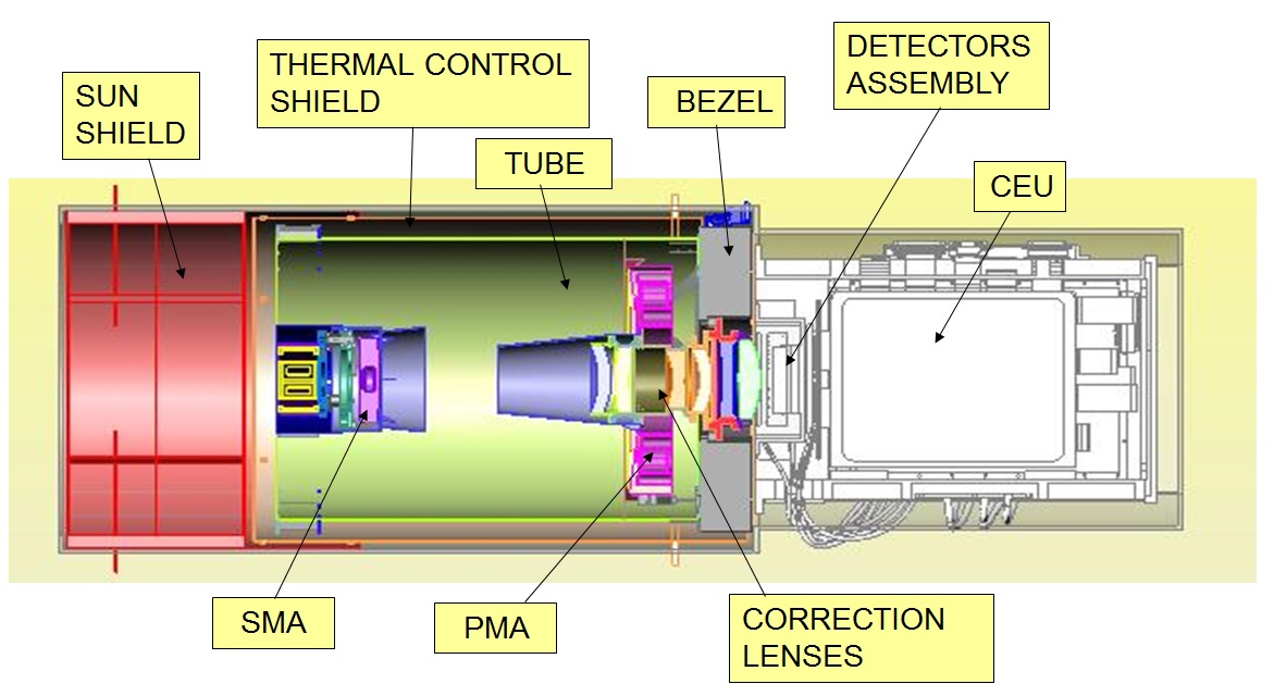
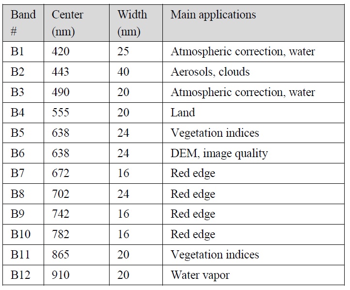
The VSSC instrument delivers 12 simultaneous, overlapping Earth images from a dozen parallel detector arrays in the focal plane, each with its unique wavelength passband. VSSC comprises a 25-centimeter aperture telescope assembly using a Ritchey-Chrétien arrangement to feed four detector units, each with three separate CCD detector arrays operated in a Time-Delay Integration scheme.
Light enters the instrument through a 22-centimeter long sun shade before the entrance of the optical module that measures 34.5 cm in diameter and 46 cm in length.
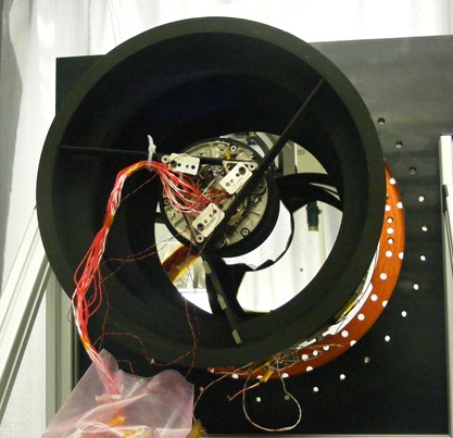
The Ritchey-Chrétien telescope is a special version of the conventional Cassegrain telescope with a hyperbolic primary mirror and a hyperbolic secondary mirror to eliminate off-axis optical errors and create high-quality imagery. Further aberrations are corrected by a reflective objective and auxiliary lenses, all made of Zerodur – a light-weight and highly stable material commonly used for optical components subjected to changing thermal environments. A similar arrangement is used by the Hubble Space Telescope and several of the world’s largest ground-based telescopes.
VSSC has a focal length of 1.75 meters and the instrument measures around 1.2 by 0.4 meters in size with a mass of under 40 Kilograms; the field of view is 1.5 by 2.2 degrees (cross-track x along-track). The optics are kept between 17 and 23°C to ensure proper focusing of the system; the structural elements holding the mirrors, lenses and detectors consist of titanium.

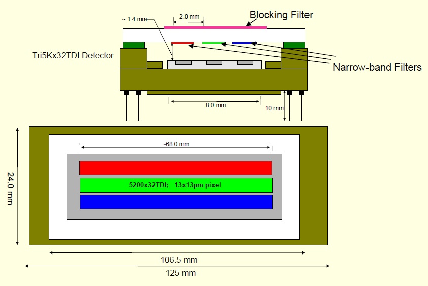
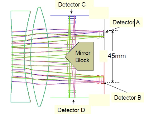
The instrument operates in a pushbroom mode – recording the image strip swept out by the satellite’s orbital motion. Four detector units, each with three separate Charged Coupled Device arrays are combined to form the VSSC focal plane assembly, employing triple-junction detectors.
Each array hosts 32 TDI (Time Delay Integration) lines with 5,200 pixels (13×13µm) per row. The number of TDI stages can be selected individually for data volume reduction and can be set at 1, 2, 4, 8, 16 or all 32 rows. The outer detector units receive the image directly from the objective, a folding mirror block is used to direct the image to the B & C detectors that are arranged orthogonal to the optical axis. In front of each detector resides the passband filters that set the wavelength & bandwidth for each channel.

VSSC does not make use of onboard calibration, though extensive calibration is completed pre-flight and in-flight calibration is performed by imaging instrumented ground sites of known properties and by collecting images of the Moon at specific phase.
The VENµS mission has a pre-arranged timeline, starting with an in-orbit test phase before the 2.5-year VM1 mission phase starts, primarily dedicated to the imaging mission of VSSC. Once a month, the IHET thrusters will be activated to gather performance data and maintain the satellite’s 720-Kilometer orbit. Additionally, once per year, mid-October through mid-November when no crops are monitored, the entire month will be dedicated to the technology demonstration mission.
During this phase of the mission, VSSC collects imagery with a 5.3-meter ground resolution across a 27.5-Kilometer ground swath. The initial SSO has a repeating pattern of 29 orbits and a local time of descending node at 10:30 local.
The VM2 mission phase includes the transfer from the 720km orbit to the second orbit at 410 Kilometers, lasting six months if the IHET thrusters operate at the planned performance. Once in the new orbit, the satellite transitions into VM3 where VSSC and IHET are operated in an interleaved scheme with VSSC taking images for three orbits followed by orbit corrections by IHET to maintain the low altitude. During periods of high-drag (e.g. increased solar activity), the chemical thrusters may be used to keep the satellite at the desired altitude.
When at 410 Kilometers, VSSC will be able to collect images at a 3.0-meter ground resolution, though the ground swath will only be 13 Kilometers wide. The orbit is designed to keep the 10:30 LTDN and two-day repeat cycle (31 orbits). After one year of operations at 410 Kilometers, the satellite will be disposed via destructive re-entry.
VENµS uses several ground segment facilities – the mission’s primary downlink station is located in Kiruna, Sweden, the Scientific Mission Image Ground Segment is located at CNES in France, and the Technological Mission Center is at Rafael in Israel. CNES is in charge of providing planning for the imaging mission and accepts all imaging data that is then processed to Level 1, 2 and 3 products for distribution to the scientific community; the Ground Segment Center at IAI is responsible for all technical aspects of the satellite’s mission – commanding the spacecraft and monitoring its performance; and finally, Rafael is in charge of processing IHET telemetry and commanding thruster operations.
CNES lists the following data products for the VENµS imaging mission:
- Level 1: Single date product, Top Of Atmosphere (TOA) reflectances, calibrated and geocoded.
- Level 2: Single date product, surface reflectances after cloud masking and atmospheric correction.
- Level 3: Multidate product, synthesis of cloud free pixels from the level 2 products acquired during a small period of time, it will be produced every 7 or 10 days.