
Swarm – Instrument Overview
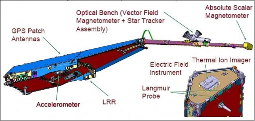
Each Swarm satellite is carrying five payloads that are used to accomplish the scientific goals of the mission – making high precision measurements of the strength, direction and variation (spatial & temporal) of the Earth’s magnetic field complemented by accurate navigation, accelerometer and electric field measurements to provide data required for modeling the various sources of the geomagnetic field.
- Absolute Scalar Magnetometer (ASM)
- Vector Field Magnetometer (VFM)
- Electric Field Instrument (EFI)
- Accelerometer (ACC)
- Laser Range Reflector (LRR)
Vector Field Magnetometer – VFM
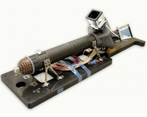
The primary instrument of the Swarm spacecraft is the Vector Field Magnetometer that was developed at DTU Space and measures the magnetic field vector. VFM consists of a triple star sensor block and a Compact Spherical Coil Vector Magnetometer – both mounted on the stable optical bench that is facilitated on the deployable boom of the spacecraft. The CSC Magnetometer is mounted on a Carbon Fiber Reinforced Polymer adapter with extremely high thermal stability while the Camera Head Units are supported by a Carbon-Silicon-Carbon bracket.
The star sensor is needed to provide extremely accurate attitude measurements that are required for the precise determination of the field vector. Three Camera Head Units are positioned with the boresights 90° from each other so that only one Camera Head is affected by Sun or Moon intrusion at a given time. The Camera Head Units are equipped with a straylight suppression system to minimize thermal excursions from the time varying sun impingement. Attitude data is produced by a micro Advanced Stellar Compass.
The VFM uses the proven fluxgate magnetometer design. VFM features a wide-range, high performance ring core fluxgate magnetometer. The fluxgate sensor uses the nonlinearity of magnetization properties for the high permeability of easily saturated ferromagnetic alloys to serve as an indicator for the local field strength. VFM has been built to minimize noise and increase magnetic stability.
The instrument consists of a non-redundant Compact Spherical Coil sensor on the boom, a redundant Data Processing Unit inside the satellite body and the connecting harness featuring a 12-meter cable 8 millimeters in diameter. The Spherical Coil that creates a homogeneous magnetic field is installed on a stable and isotropic mechanical structure. The VFM sensor is held in place by a sliced adapter ring.
The symmetry of the positive and negative magnetic saturation levels of the ferromagnetic sensor core allow the operation of the fluxgate magnetometer by constantly probing the core saturation levels by a high frequency excitation magnetization current that enables the sensor to detect minute deviations from the zero field.
Noise on the instrument is only a few Picotesla while VFM provides a long-term stability in the sub Nanotesla range.
VFM has a dynamic range of ±65536.0 nT to 0.0625nT with high omnidirectional linearity, low noise and a sampling rate of 50 Hz. Overall, the instrument achieves an accuracy of under 0.5 Nanotesla for magnetic measurements and 0.1 degrees for attitude knowledge. The CSC Sensor Head is 82 millimeters in diameter and weighs 280 grams while the Data processing Unit weighs 750 grams being 100 by 100 by 60 millimeters in size.
Star Tracker Assembly
Absolute Scalar Magnetometer – ASM
While VFM provides information on the direction of the magnetic field, the ASM instrument measures the overall strength of the magnetic field. The instrument was developed by the French Space Agency CNES and the French Atomic Energy Commission. ASM uses a new instrument design approach from lessons learned during previous missions which used proton-procession nuclear magnetic resonance probes.
The ASM instrument uses atomic spectroscopy with Helium 4 – making use of the Zeeman effect. Spectral lines can be split into several components in the presence of a magnetic field while the energetic distance between the Zeeman sub-levels is a function of the magnetic field – enabling measurements of the magnetic field by determining the Zeeman levels. ASM uses signal amplification by optically-pumped atoms of Helium 4.
Using this measurement principle enables ASM to determine the magnetic field strength with high sensitivity and performance, which remains identical at all points in the orbit. ASM makes absolute measurements without any drift or bias.
ASM can also determine components of the magnetic field along three axes perpendicular to each other resulting in magnetic field vector measurements that can be used to compare VFM against ASM data to verify the design of the ASM sensor for future missions.
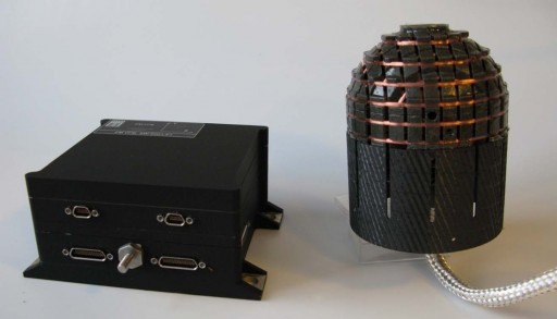
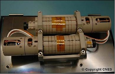
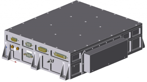
The ASM instrument consists of two major components – a Data processing Unit and the Sensor Unit that is connected to the DPU via optical fibers and electrical cables. Two identical sensors are installed on the tip of the deployable boom to provide redundancy to the system that also features two DPUs – one for each sensor.
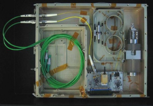
The DPU consists of two stacked modules – a CV/Laser Module and a mixed module. The CV/Laser Module uses a 1083nm laser system that is connected to the sensor via an optical fiber. It also includes primary and secondary power conversion modules.
A dedicated CV card provides the secondary voltages of 5 and 3.3 Volts to the sensor electronics. The laser source provides the optical power to the sensor. An optical interface unit facilitates the pump laser diode, two photodiodes and low noise amplifiers as well as other electronics.
The Mixed Card contains the main digital and analog circuits in charge of regrouping the main digital core, electrical interfaces and a test socket, the data acquisition and processing modules as well as the radio- and high-frequency electronics, the laser, the piezoelectric motor and vector mode drivers.
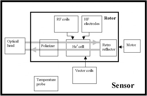
The ASM sensor module facilitates a rotor that consists of a Helium 4 cell, a polarizer, a retroreflector and coils that generate radio- and high-frequency signals. The Helium 4 cell contains a low-pressure Helium gas that is used for the measurements. The high-frequency electrodes apply an electric discharge to the Helium 4 atoms which are then transferred from their ground state to a metastable level. The Radio-Frequency coils the provide an RF field to the excited atoms to induce the magnetic resonance between the Zeeman sublevels of the metastable excited state.
A linear polarizer ensures optimal pumping conditions of the Helium gas while the retroreflector is used to reflect laser light back through the cell to the Optical Head. Complete isotropy of the sensor is achieved by keeping a constant 90-degree angle between both polarization and RF field directions and the ambient magnetic field. Three orthogonal vector coils are used when the system is operated in vector mode to create vector modulation that are superimposed on the static field.
The metastable Helium level is split by the Earth’s magnetic field into three Zeeman sublevels that are measured using a photodetector. The energy difference is directly proportional to the ambient magnetic field strength and equals half the gyro frequency.
A temperature sensor is used to provide the sensor head temperature to the Data processing Unit for heater actuation.
The laser itself features a complex architecture that consists of a pump laser diode, a Wavelength Division Multiplexer WDM, an Ytterbium doped Fiber Bragg Grating and an optical isolator and splitter for feedback control. The emitted laser light at 980nm is transmitted to the WDM and Laser Fiber Assembly that generate a 1082.908nm signal that is passed to the optical isolator and the splitter that directs 80% of the output to the sensor and 20% back to the pump diode.
In this feedback architecture, the noise reduction loop acts on the current of the pump diode by detecting low frequency fluctuations of the optical output power from the dedicated photodiode. This design approach has been chosen to ensure that the 1082.908nm frequency needed for pumping the 4He is achieved without thermal drifts. A 1083nm laser diode with a Peltier Cooler would have increased instrument power consumption.
A piezoelectric actuator modulates the Laser Fiber Assembly for fine-tuning of the laser wavelength to match the wavelength of the Helium transition frequency.
The ASM has two sensors are installed on the tip of the deployable boom using a sensor mount structure. The harness that connects the sensor to the DPU includes two optical fibers the provide the laser light to the sensor chamber and transmit the reflected radiation back to the DPU for analysis. Also included in the harness are two coaxial cables and six twisted pairs of electrical wires that are needed to drive the motor, the HF discharge and the RF Coils. The DPU itself uses the 1553 satellite data bus and it is also connected to the primary power supply and the GPS clock for data time-tagging.
The ASM instrument weighs 3 Kilograms, the sensor head is 40 by 60 millimeters in size and the DPU is 200 by 150 by 100 millimeters in size. The instrument has a dynamic range of 15000 to 65000 nT with an accuracy of less than 0.3 Nanotesla. ASM has an omni-directional response of under 0.1nT.
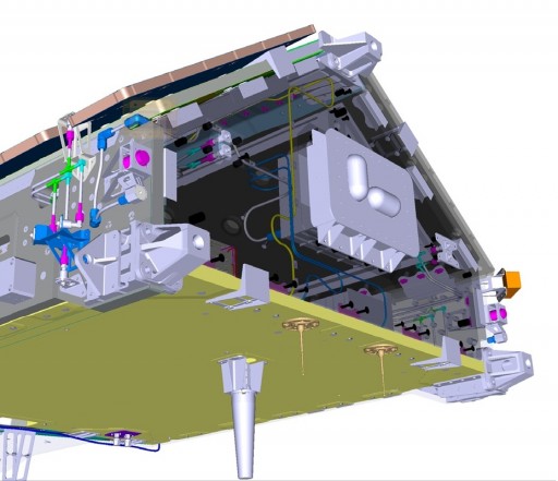
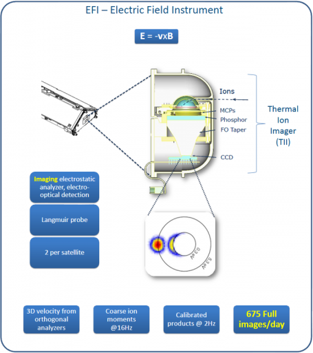
Electrical Field Instrument – EFI
The EFI, also known as CEFI – Canadian Electric Field Instrument, is provided by the Canadian Space Agency, the University of Calgary and ComDev Ltd. The instrument will characterize the electric field around the Earth by measuring the plasma density, drift, and acceleration at high resolution; also for plasma density mapping in conjunction with GPS.
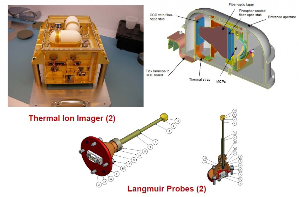
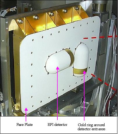
EFI consists of three major components: the Suprathermal Ion Imagers, the Langmuir Probe and the Electronics Assembly.
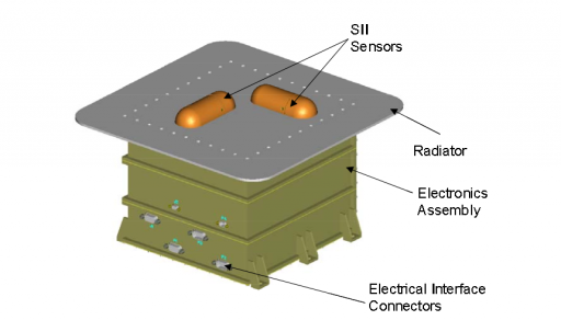
The Electronics Assembly contains all instrument electronics needed for power supply, sensor data acquisition & processing, instrument control & command execution as well as communications with the spacecraft bus. The EFI sensors are positioned on the Ram Side of the Swarm spacecraft. The ram side of a spacecraft is the side facing the direction of the satellite’s motion. It rams/impacts the fluid that the satellite moves through, in Swarm’s case the particle environment of Earth. The Langmuir Probes are located ram-nadir.
The Suprathermal Ion Imagers are two-dimensional spherical particle imagers that follow a design approach that was developed at the University of Calgary. Ions enter a narrow aperture slit and are then deflected by two hemispherical grids that act as the electrostatic analyzer. The grids create an electric field that is directed radially inward.
Low-energy ions are accelerated and deflected toward the center of the spherical sensor while ions with larger energies are deflected farther to the edge of the sensor which creates an ion energy spectrum as a function of the detected radius. Ions coming from out-of-plane directions strike at different positions on the image plane.
Each SII sensor creates a two-dimensional image that represents a 2D cut through the ion distribution function that allows scientists to determine ion density, drift velocity, energy and higher-order moments. To create a three-dimensional image, the two SII sensors are oriented so that their apertures are positioned perpendicular to each other allowing the two cuts to be combined into a 3D image.
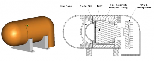
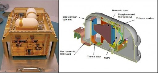
The SII sensors are equipped with Microchannel Plate Detector Assemblies, a phosphor-coated fiber taper and a frame transfer Charged Coupled Device (CCD). When striking the MCP, ions generate a signal that is amplified by secondary emission processes. The voltage applied to the MCP can be regulated to control the gain of the instrument – in orbital passages with high ion flux, the voltage can be reduced to limit the gain of the device and prolong its lifetime. The gain is controlled by an autonomous system that uses a feedback loop which uses the EFI faceplate current as control input. When instrument gain control can not be achieved by the MCP alone, an electrostatic shutter will gate the incoming ions with a duty cycle of 1 to 100%.
After striking the MCP and initiating secondary emissions, the charge strikes a phosphor screen that acts as coating on a fiber taper. As a result, photons are emitted and the electrical signal is converted to an optical signal. The fiber taper reduces the image size to match the active area of the CCD detector that creates the instrument images. A test LED is located near the CCD for instrument aliveness checks and calibrations.
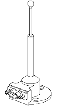
In addition to the SII sensors, the EFI instrument also features two Langmuir Probes. Langmuir probes can determine electron temperature, electron densities and the electric potential of a plasma. Two electrodes are inserted into a plasma environment. The electrodes have a constant or time-varying electric potential between them to allow the determination of physical plasma properties by measuring currents and potentials in this two-electrode system. A bias voltage is applied to the probe and the resulting current that is measured is proportional to plasma charge density.
Using a two-probe design allows Swarm to make simultaneous measurements of of electrons and ions by applying a positive bias to one and a negative bias to the other. Two probes on equal potentials can also be used for interferometric measurements.
EFI uses small Langmuir Probes that are about 10 millimeters in size.
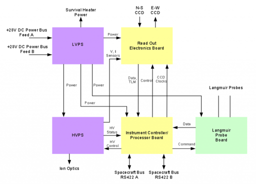
The EFI instrument electronics assembly consists of a number of components that are connected to each other and the sensors via a wire harnesses. The primary 28-Volt power bus of the spacecraft interfaces with a Low-Voltage Power Supply that provides power to the individual instrument electronics and heaters. A High-Voltage Power Supply uses the 5-Volt bus from the LVPS and generates the high voltages needed for the electrostatic analyzers on the two SII sensors and the MCPs and the phosphor. An Instrument Controller/Processor Board controls the high-voltage units and the other instrument functions. ICP consists of a processor, a control FPGA, an EEPROM nonvolatile memory, SDRAM for volatile memory, an oscillator, a D/A converter and RS-422 serial interfaces.
The ICP is connected to the Read-Out Electronics Board that interfaces with the SII sensors and provides data and telemetry to the ICP which delivers commanding and clock data to the Read Out Electronics Board. The Read-Out Electronics Board provides the signal conditioning and readout chain, programmable voltage CCD clock drivers, test LED actuation and housekeeping data multiplexing and Analog-to-Digital conversion.
The SII CCDs are connected to two pre-amp circuit boards inside the SII heads that provide the amplified instrument signal to the Readout Board for A/D conversion and relay to the ICP. SII electrostatic shutter actuation is completed by the ICP that senses instrument skin current and determines the required shutter control parameters before sending the appropriate control waveform to the High-Voltage Power Supply.
The High-Voltage Power Supply provides the current voltage settings to the Read Out Electronics Board for instrument operations.
Also connected to the ICP is the Langmuir Probe Board that regulates the floating voltage and measures the current in the electrode system as well as the spacecraft potential. The LP Board receives commands from the ICP and switches between its different measurement modes as commanded providing its instrument data including science data and telemetry to the ICP. The ICP itself is connected to the spacecraft data system via a redundant RS-422 data bus to transmit science data and telemetry and receive uplinked commands.
The EFI instrument consists of aluminum alloy used for its low mass, high strength and good thermal conductivity. The instrument is attached to the spacecraft via six attachment points. The SII sensors are directly installed on the radiator for heat rejection in order to limit dark current on the CCD.
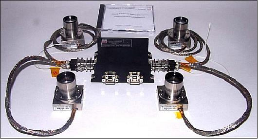
Micro Accelerometer 04 – MAC-04
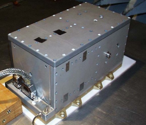
MAC-04 is an electrostatic instrument that was designed and developed at the Aeronautical Research and Test Institute, Prague. Its main objective is to precisely measure non-gravitational perturbing accelerations with temporal and spatial variability. Factors that cause non-gravitational accelerations are air drag, winds, Earth albedo (reflected solar radiation and thermal radiation) and direct solar radiation pressure. MAC-04 data can provide air density measurements that can be used with magnetometer data to provide new insights into geomagnetic processes.
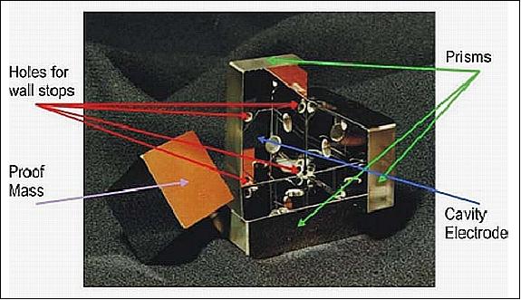
MAC-04 uses a cubic proof mass that is free-floating in the cubic cavity that is separated from external influences by the Swarm satellite structure and the construction of the accelerometer itself that is located near the spacecraft Center of Gravity. The cubic cavity is rigidly attached to the satellite body so that gravitational as well as all perturbing forces acting on the satellite are identical to those acting on the cavity. Within the cavity, the proof mass can move freely. The difference between the acceleration of the cavity and the acceleration of the proof mass is equal to the sum of all accelerations generated by non-gravitational forces.
Measuring the position of the proof mass allows even minute displacements to be detected and counteracted by applying a known electrostatic force so that the action of non-gravitational forces can be measured as a function of counteracting force settings. The proof mass position control is accomplished via electrodes that are actuated through a feedback loop that drives servo control electronics.
The MAC-04 instrument provides three vector components of linear and angular accelerations and positions as well as eight temperature sensor values.
MAC-04 is 17.7 by 20.4 by 36.0 centimeters in size with a total instrument weight of 6.06 Kilograms.
Laser Retroreflector
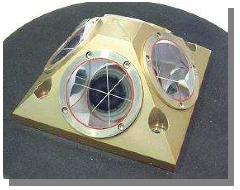
Each Swarm satellite is equipped with a Laser Retroreflector to provide the opportunity for precise orbit determination. The LRR consists of a regular 45-degree pyramid shaped retroreflector array and was manufactured at GeoForschungszentrum, Potsdam, Germany. The LRR is identical to those flown on several previous ESA and CNES missions.
It is a passive payload that features four prisms to reflect short laser pulses back to the transmitting ground station. The prisms consist of fused quartz glass with a refractive index of 1.461 at 532 nanometers, coated with aluminum & a protective layer of silicon dioxide. Measuring direct two-way range between the ground station and the laser can be accomplished with an accuracy of one to two centimeters.
The LRR weighs 400g and is 10 by 10 by 4.8 centimeters in size.