
Tsubame
Tsubame is a microsatellite project of Matunaga LSS (Laboratory for Space System) at the Tokyo Institute of Technology that combines technical and scientific mission objectives. The 50-Kilogram satellite will demonstrate an agile attitude control system based on Control Moment Gyros, acquire Earth imagery and study gamma-ray bursts and X-ray emissions.
Tsubame means ‘swift’ – a name chosen to reflect on the mission’s objective of demonstrating a quick attitude control system and due to parallels with NASA’s Swift mission that also studies gamma-rays.
The overall technical goals of the mission are the demonstration of the microsatellite bus that includes Commercial Off The Shelf COTS components, the demonstration of the Control Moment Gyros and the demonstration of a high-resolution optical imager.
Scientific goals identified for this mission are the observation of gamma- and X-ray sources in a responsive system that uses the satellite’s high agility to automatically identify and point the instrument to events of interest.
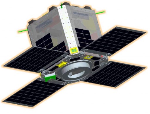
The satellite uses a nearly cubic platform measuring 50 by 50 by 47 centimeters, comprised of a lattice structure and external panels. Four solar panels are deployed once in orbit to face in the same direction and ensure optimal power-generation when in sun-pointing mode. The side panels of the satellite are outfitted with additional solar cells to ensure some power is generated in any spacecraft orientation. Tsubame uses indium-gallium-arsenide solar cells that are grouped in six strings, interfacing with the EPS Board and a 6-cell Lithium-Polymer battery.
The EPS board controls the state of charge of the battery and provides solar array shunting when required. Overall, the solar cells deliver more than 100 Watts of electrical power. Using DC to DC converters, the EPS hardware generates voltages needed by other electronic components of the satellite, conditioned from an unregulated power bus at 25-32 Volts.
Thermal control of the satellite uses multilayer insulation to keep all components in a stable thermal environment. More than 40 temperature sensors are used to keep track of temperatures in various positions of the satellite.
The Attitude Determination and Control System uses CMGs and Magnetic Torquers for attitude actuation and a series of sensors for navigation and attitude control. Each satellite panel is equipped with one sun-sensor to allow a fast determination of the solar direction and point the solar panels at the sun in case of spacecraft safe mode. A three-axis magnetometer and a redundant set of two star trackers are used for precise attitude determination in combination with Fiber Optic Gyros that accurately measure body rates.
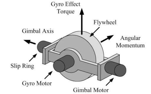
The miniature Control Moment Gyroscopes are the primary focus of Tsubame’s technical demonstration mission. Four CMGs are installed in a pyramide to be able to provide three-axis stabilization with agile pointing capability. A CMG consists of a spinning rotor and motorized gimbals that can tilt the rotor’s angular momentum resulting in a gyroscopic torque acting on the spacecraft, causing it to rotate since the CMGs are firmly installed on the spacecraft structure. CMGs differ from reaction wheels that impart toque by simply changing the speed at which they rotate. Overall, CMGs require less energy and deliver much higher torque than reaction wheels which are simpler in design and for most spacecraft are the best solution.
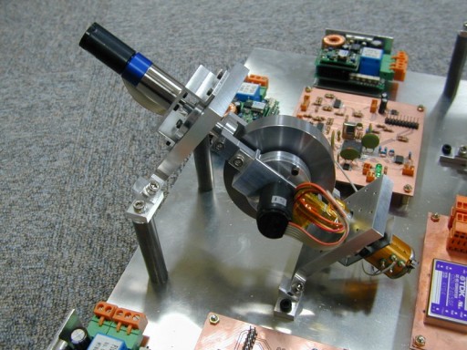
Each CMG used on Tsubame is 7.35 centimeters in diameter with a total length per assembly of 15 centimeters and a mass of 1 Kilogram per wheel. The wheel is rotated by a synchronous motor to generate an angular momentum of 0.053 Nms. A step motor is used to gimbal each wheel along one axis with a speed of +/-1.0rad/s while an RV resolver delivers the current gimbal position to the ADCS controller as feedback. Overall, the CMGs used on Tsubame can generate 53mNm of torque for very fast re-orientations of the spacecraft while maintaining a pointing accuracy of 1° and a stability of better than 0.5°/s.
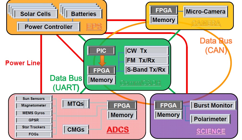
The Tsubame spacecraft uses a central Onboard Computer based on Field Programmable Gate Array technology to control all vehicle functions and sequences, and handle all housekeeping and payload data as well as communication tasks. A Peripheral Interface Controller is used to monitor the OBC health. The OBC interfaces with other systems using a CAN data bus with the exception of the Electrical Power Systems and the Peripheral Interface Controller that use UART links (Universal Asynchronous Receiver/Transmitter).
Communications are done via the amateur VHF/UHF bands for command uplink and housekeeping data downlink while S-Band is used for payload data transmission. The 430MHz UHF downlink channel reaches data rates of 9.6kbit/s while the 144MHz VHF uplink is done at 1.2kbit/s. The S-Band system uses BPSK modulation and reaches downlink data rates of 100kbit/s.
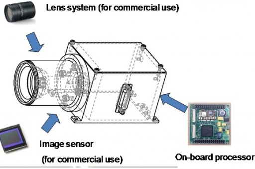
Tsubame is equipped with two payloads – an Optical Camera and a Gamma-Ray Observation System, GROS. The optical camera is used for Earth observations at moderate resolutions for use in landmark tracking, environmental monitoring, and panorama imaging.
The Optical Camera is 9 by 10 by 20 centimeters in size with a total instrument mass of 1 Kilogram and a power demand of 3 Watts or less. A Field Programmable Gate Array is used as an instrument controller, responsible for the operation of all the camera’s functions.
The camera has a focal length of 17.5 centimeters and uses a detector of 2,210 by 3,002 pixels that can operate at a read-out speed of up to 5 images per second. The Optical Imager achieves a ground resolution of 14 meters.
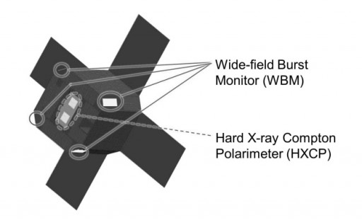
GROS, the Gamma Ray Observation System consists of two main components – the Wide Field Burst Monitor (WBM) and the Hard X-Ray Compton Polarimeter (HXCP). WBM is in charge of the detection of Gamma-Ray Burst Events (GRBs) and determine their direction so that HXCP can be pointed to the event location for observation taking advantage of the satellite’s high agility provided by the Control Moment Gyros, pointing the satellite to the proper viewing direction for HXCP within 15 seconds.
The Wide Field Burst Monitor consists of five separate units that point to different directions. WBMs are flat plate CsI scintillators 6 by 6 centimeters in size and 0.5 centimeters in depth. Continuous count rates of the WBMs are received by the Main Processing Unit. When an increase in count rates is sensed, basic centoid calculations can be made to determine the direction of the event by using data provided by all five sensors. The calculation is done with an accuracy of +/-10° which is sufficient to then position the satellite for event viewing by the HXCP instrument. The re-orientation is completed within 15 seconds from the event trigger.
Each WBM weighs 260 grams and has a minimum energy threshold of 30keV and a minimum count rate of 10 Hz.
HXCP, the Hard X-ray Compton polarimeter aims to analyze the polarization plane of x-rays entering the instrument to yield information on the mechanism of the emission – the distribution of magnetic field, radiation field and matter around the sources which are rotating pulsars, accreting black holes and active galactic nuclei. Polarization analysis has not been performed on a reliable level at different energies and information provided by the instrument is hoped to increase understanding in x-ray and Gamma-ray sources.
The HXCP instrument is pointed to the direction of an even within 15 seconds of the trigger and so can observe the majority of x-ray events that commonly have durations on the order of 40 seconds. HXCP can detect photons at an energy range of 30 to 200 Kilo-Electronvolt utilizing the azimuthal angle anisotropy of Compton scattering.
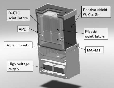
The instrument consists of a scatterer that is used to determine the incidence angle of incoming X-rays before the photon energies are detected by using an absorber. The scatterer consists of 64 (8 by 8) plastic scintillators (6.5 x 6.5 x 49mm) located in the center of the detector while the absorber uses 28 Cesium Iodide scintillators (6.5 x 10 x 49mm). The scintillator signals are read-out by photomultipliers (Multi-Anode Photo Multiplier Tubes Avalanche Photodiodes).
HXCP has a field of view of +/-15 degrees with an effective detector area of 7cm².
To subtract x-ray background radiation and atmospheric gamma rays, the instrument uses a coincidence technique, rejecting all events that do not strike the scatterer and absorber at the same time. Background rejection is also optimized by the shielding of HXCP consisting of lead, tin and copper.
