SaudiSat-4
SaudiSat-4 is a Saudi-Arabian technology demonstration satellite that was developed by the King Abdulaziz City for Science & Technology with input from NASA Ames to conduct a UV LED Experiment in space that will demonstrate UV LED technology and also study AC charge management in LEO satellites.
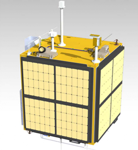
SaudiSat-4 weighs approximately 112 Kilograms based on a modified version of the SaudiSat-3 satellite bus with a mass of 83 Kilograms.
The spacecraft uses four fixed solar panels to generate 61 to 86 Watts of electrical power that is distributed to the various satellite subsystems including the payload that requires 45 Watts of power during operation. Batteries are used to store up to 450 Watt-hours of electrical power.
The satellite is three-axis stabilized using two star trackers, magnetometers and sun sensors to acquire orientation data for precise pointing using a reaction wheel assembly. SaudiSat-4 has no propulsion system for orbit control.
The spacecraft uses an integrated avionics unit that houses the onboard computer and other avionics that control all satellite functions and execute commands sent from the ground, actuating all subsystems and commanding payload operations. SaudiSat-4 has a mass memory of 25Gbytes that can accept data are rates of up to 25Mbps. The satellite uses an X-Band communication system achieving a downlink data rate of up to 358 Mbit/s.
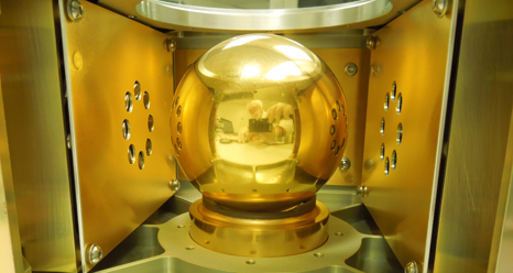
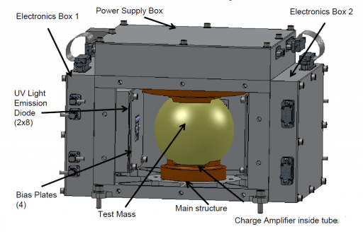
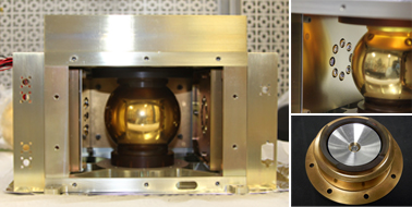
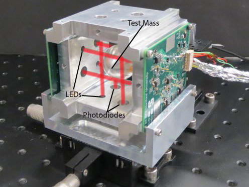
The heart of the satellite is its payload – a Modular Gravitational Reference Sensor and a UV LED Charge Management System for demonstration in orbit. The system consists of a proof mass – a 700-gram sphere that is coated with gold, four bias plates, 16 UV LEDS, a contact probe and gold-coated Ultem tubes for shielding.
The Gravitational Reference Sensor using a free-floating test mass on drag-free spacecraft requires the control of charge build-up on the proof mass. The GRS is an accurate accelerometer that is limited by the charge build-up on the free floating test mass. A GRS is used to allow a spacecraft to fly in an orbit that is solely influenced by gravity and not affected by solar pressure and atmospheric drag. This type of drag-free flight scheme is utilized in gravity sensing spacecraft.
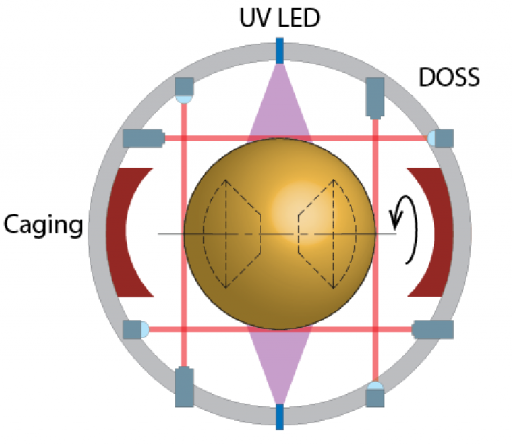
The UV LED System is designed to remove the charge build-up on the test mass by exposing it to UV illumination which creates a cloud of electrons as a result of photoemission leading to the discharge of the sphere. The discharge rate is controlled with electrodes that are biased in voltage.
Using the LEDs and bias in phase (0°), photoelectrons are transported from the test mass to the electrodes creating a positive charge transfer. When the LEDs and voltage bias are operated out of phase (180°), photoelectrons are transported from the electrodes to the test mass as part of a negative charge transfer. The LEDs have a wavelength maximum at 255 nanometers.
The displacement of the test mass is measured by an Differential Optical Shadow Sensor that uses eight LEDs and photodiodes on the opposite side of the cage of the test mass are used to determine the displacement of the test mass as a function of light intensity measured by the photodiodes. The DOSS system achieves a 10-nanometer resolution at a frequency of up to 1Hz.
The caging mechanism has been designed for a 200-Newton holding force to restrain the sphere during launch.
SaudiSat-4 will qualify the UV LEDs for spacecraft and demonstrate the AC charge management system. The success of the GRS will increase the capability of gravitational reference sensors for future missions that are currently under development such as the Laser Interferometer Space Antenna (LISA).
Future nano and microsatellite missions will carry Modular Gravitational Reference Sensors using different variations such as grating angular sensing and diffractive optics as well as micro and nanothrusters to eventually develop the MRGS for scientific missions.