
MicroSCOPE
MicroSCOPE is a minisatellite mission of the French and European Space Agencies with involvement of a number of European institutions to conduct a fundamental physics experiment testing the General Theory of Relativity. The 330-Kilogram satellite hosts a series of payloads to gather data on the Weak Equivalence Principle (WEP) which postulates that a perfect proportionality exists between the inertial mass and the gravitational mass of a body.
Resulting from the WEP is the ‘Universality of Free Fall’ which states that all objects fall with exactly the same acceleration in the same gravitational field. The Equivalence Principle is a major part of Albert Einstein’s Theory of Relativity and experiments on Earth have so far returned the best accuracy value of EP at 10^-13. MicroSCOPE will employ state of the art technologies to improve the value by two orders of magnitude.
The MicroSCOPE concept is similar to that of the STEP (Satellite Test of the Equivalence Principle) mission designed in 1989 but never realized. MicroSCOPE uses ultra-sensitive accelerometers, micro thrusters, and simultaneous spin control and drag-free flight in order to obtain its measurements. A number of complex technologies are brought together in this mission such as continuous drag-free control, hybrid attitude control through star sensor and accelerometer data, micro-newton cold gas thrusters, passive thermal control with milli-Kelvin accuracy, and an electrostatic differential accelerometer with femto-G precision.
The French Space Agency CNES is responsible for the microsatellite (the satellite bus, testing and payload integration), ESA provides the micro thruster system, mission and data analysis is completed by OCA and ONERA, and the Center for Applied Space Technology and Microgravity in Bremen is responsible for drag-free system design and accelerometer testing.
The MicroSCOPE project was put forward in 2000 and is based on the principle of placing two test masses made from different materials into an identical gravitational environment and measuring their free fall motion while ensuring both masses are submitted to the exact same gravitational field, eliminating any outside perturbations. An electrostatic field is applied to the masses to force the masses to remain on the same orbit – the required field is accurately measured and a defect in experiment symmetry would provide evidence of an EP violation.
MicroSCOPE is a very complex undertaking because of the requirement of removing any and all external disturbances arising from non-gravitational forces such as drag, radiation pressure, thermal variations and electromagnetic forces. The satellite employs a micro-propulsion system operating along six degrees of freedom for attitude and linear acceleration control to place the test masses into a perfect drag-free environment at very low noises.
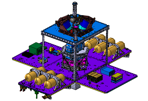
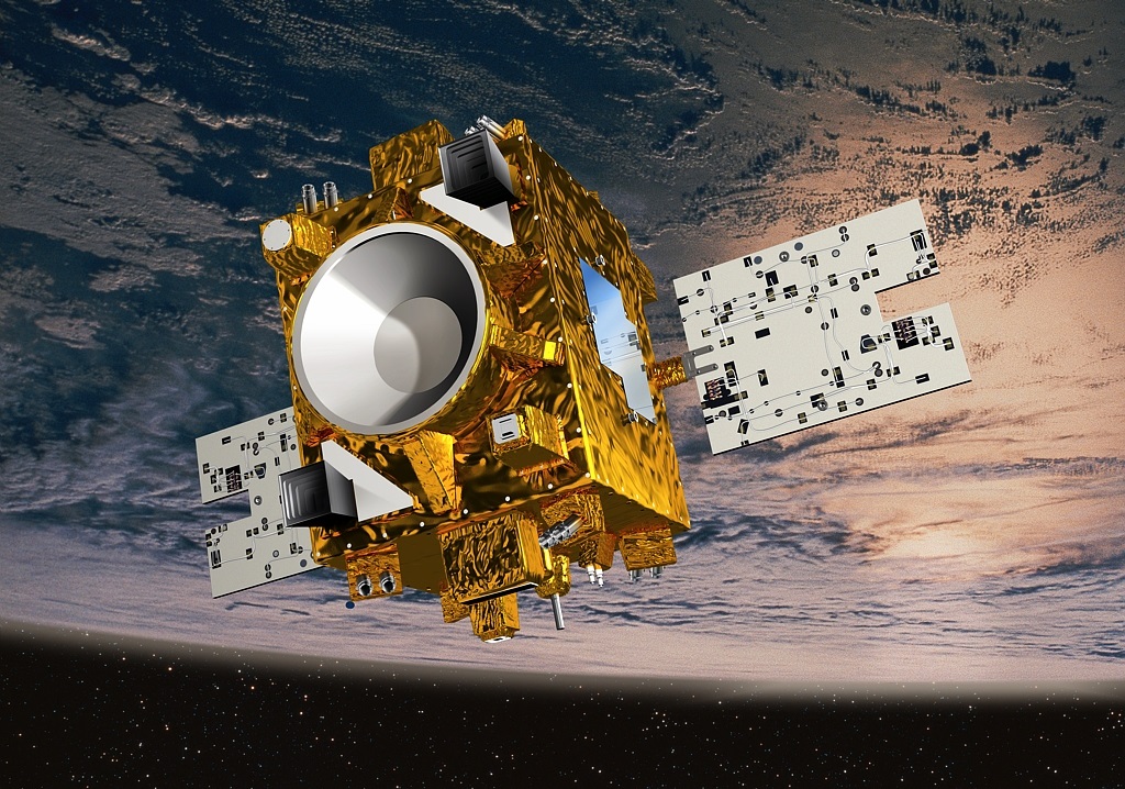
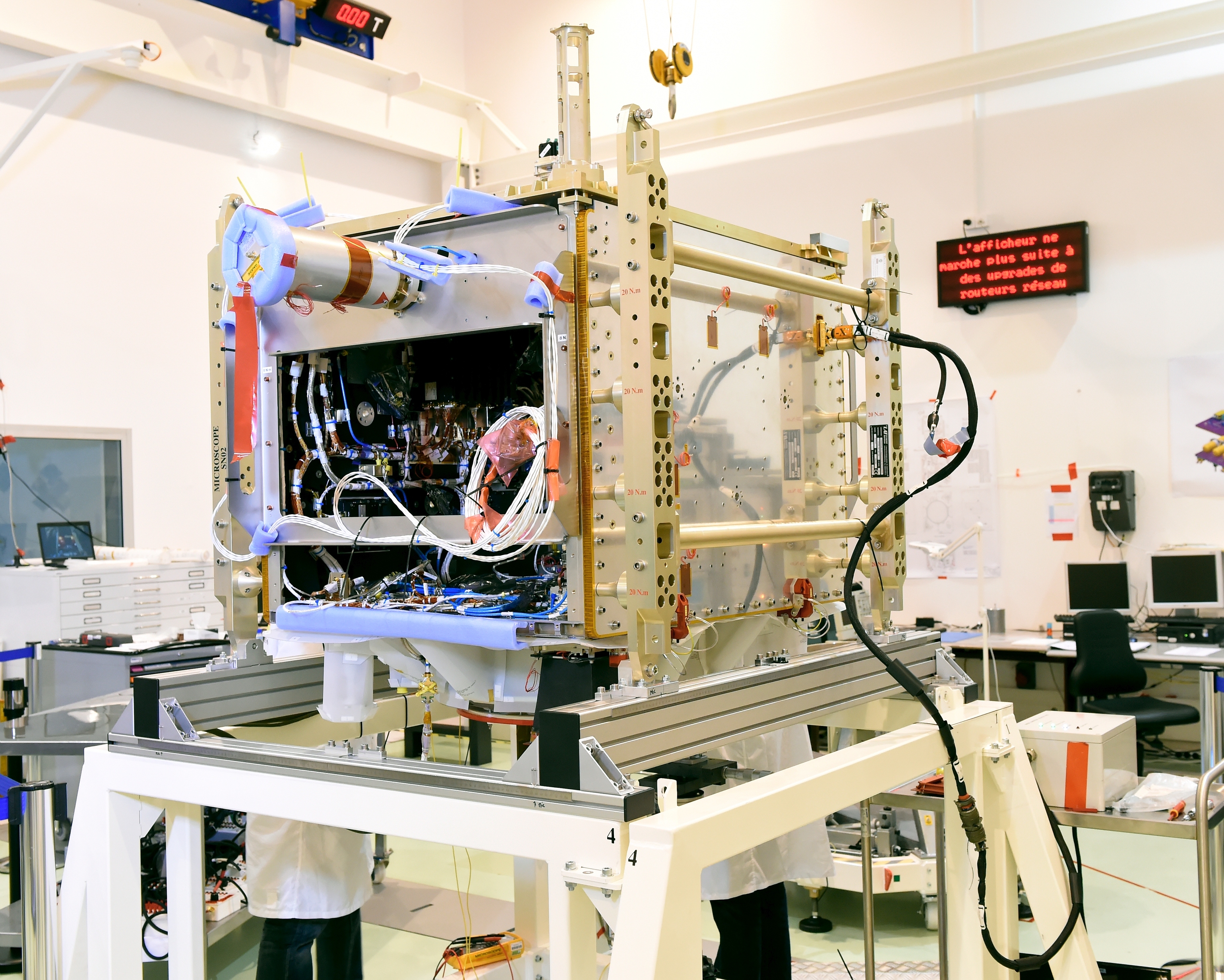
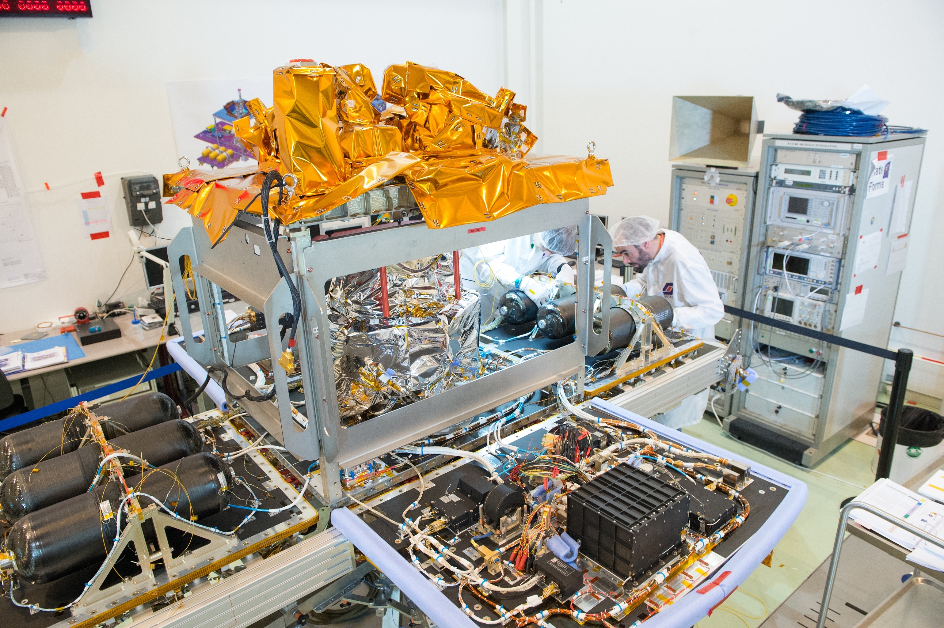
The MicroSCOPE satellite is based on the Myriade satellite bus for microsatellites, developed by CNES and flown on a number of missions. The bus is cube-shaped, 138 by 104 by 158 centimeters in size when in its launch configuration, capable of facilitating mid-sized payloads. Structurally, the satellite platform is comprised of a honeycomb-and-plate structure with lateral panels held by L-spar support structures that permit the side panels to be opened independently during satellite integration.
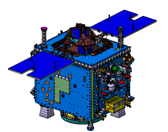
The Z-deck of the spacecraft hosts the CGPS (Cold Gas Propulsion System), the Y-panels facilitate the satellite subsystem components, the -X wall has the Star Tracker Optical Heads and provides structural interfaces for the Payload Assembly Subsystem.
Myriade was chosen for this mission in a compromise between the high performance required for MicroSCOPE and the cost effective and robust architecture of the satellite platform. MicroSCOPE employs the Myriade platform with all of its subsystems operated decoupled from a modular payload system facilitated within the central part of the platform structure.
A pair of deployable solar arrays are hinged on the zenith panel of the satellite (Y) and deploy to the +X direction from a position folded up against the satellite side panels. The arrays are held in place by three pyrotechnic locks and deployment is completed by a pair of Carpenter blades. A total area of 1.6 square meters is covered with Gallium-Arsenside solar cells generating a total power of 140 Watts, stored in a 14 Amp-hour battery unit and distributed to the various subsystems by a dedicated Power Conditioning and Distribution Unit, also in charge of battery management, thruster and magneto-actuator commanding.
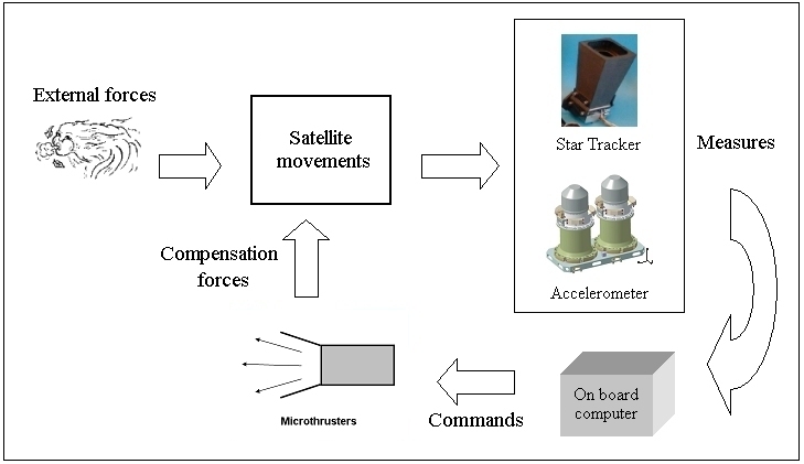
The satellite is flown either spin-stabilized directed normal to the plane of the orbit, three-axis stabilized, or in drag-free mode. MicroSCOPE employs an Attitude and Acceleration Control Subsystem that is in charge of three functions: the control of the three-axis attitude of the satellite, the control of linear accelerations on the satellite (drag compensation), and the the generation of linear and angular excitations for instrument calibration.
Satellite attitude determination is accomplished with three coarse sun sensors, a three-axis magnetometer and a pair of Star Trackers. Attitude actuation uses the Drag-Free Attitude Control System during the operational mission phase. Reaction wheels and magnetic torquers are installed on the satellite for use during the initial injection phase and during potential satellite safe modes.
The AACS (Attitude and Acceleration Control Subsystem) also makes use of the scientific payload of the instrument, SAGE, for the measurement of angular and linear accelerations. In the nominal mission mode, the only active attitude sensor is the µASC (micro Advanced Stellar Compass) comprised of a pair of Star Tracker Units.
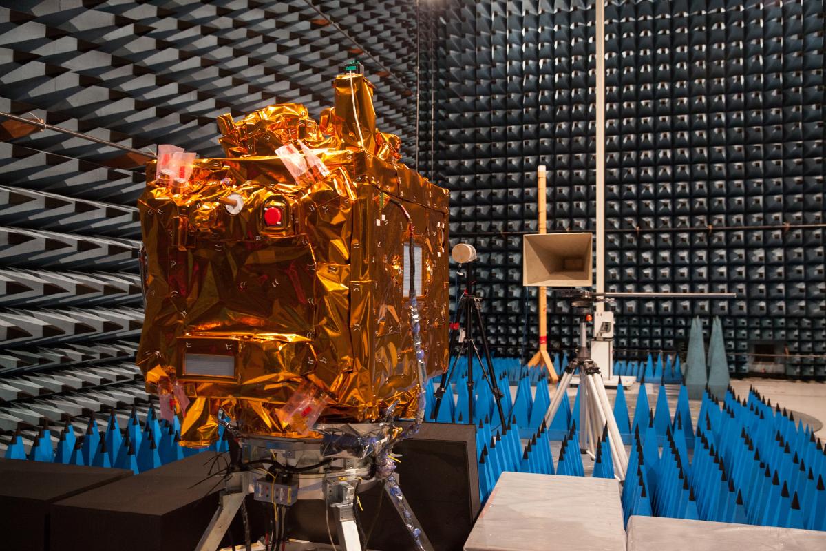
Thermal control on the satellite purely relies on passive methods, transporting excess heat from the internal electronic components to external radiators installed on the satellite side panels.
The Payload Assembly Subsystem is installed on the anti-sun panel of the spacecraft (-X) to be able to use the high natural external flux stability of this S/C side along the 6-hour local time dawn-dusk orbit, thus avoiding thermal cycling from Earth’s radiative heat flux. The Payload Assembly Subsystem is made of a two-stage structure – the Front End Electronics Units (FEEUs) are centered on the first stage for thermal stability purposes while the accelerometer sensor units are centered on the second stage where thermal stability is better than 1mK. Multi-layer insulation is used for radiative thermal shielding of the payload.
Overall, the MicroSCOPE payload weighs 50 Kilograms and measures 54 by 50 centimeters in size. It occupies the entire central section of the spacecraft and the satellite design is governed by mass and thermal symmetry as well as thermal stability to provide a conducive environment to the sensitive payload.
The spacecraft controller is built around a Transputer T805 used as onboard computer with a 1Gbit solid state memory and support of I²C data buses. Communications are accomplished with a functional S-Band chain with a data rate of 625kbit/s.
The primary objective of the sensor payload of the MicroSCOPE spacecraft is to expose two test masses to the same gravitational environment and measure whether they are affected in the exact same way. Because the two masses can not be idealized point masses, local gravity gradients will affect their behavior and have to be factored into calculations.
The experiment, in essence, controls the free fall motion of a pair of quasi-cylindrical masses of different materials flying in the same orbit. Both are subjected to the same gravitational environment in Low Earth Orbit. To have an identical gravitational field acting on the two masses, they have to be concentric with a common center of gravity and their shape must be chosen so that gravity gradients are identical on the two masses.
The experimental setup requires the masses to be shielded from non-gravitational influences such as drag, radiation pressure from the sun and Earth as well as electromagnetic forces. For these purposes, MicroSCOPE carries a micro-propulsion system and precise accelerometer units to work in unison and cancel out external disturbances.
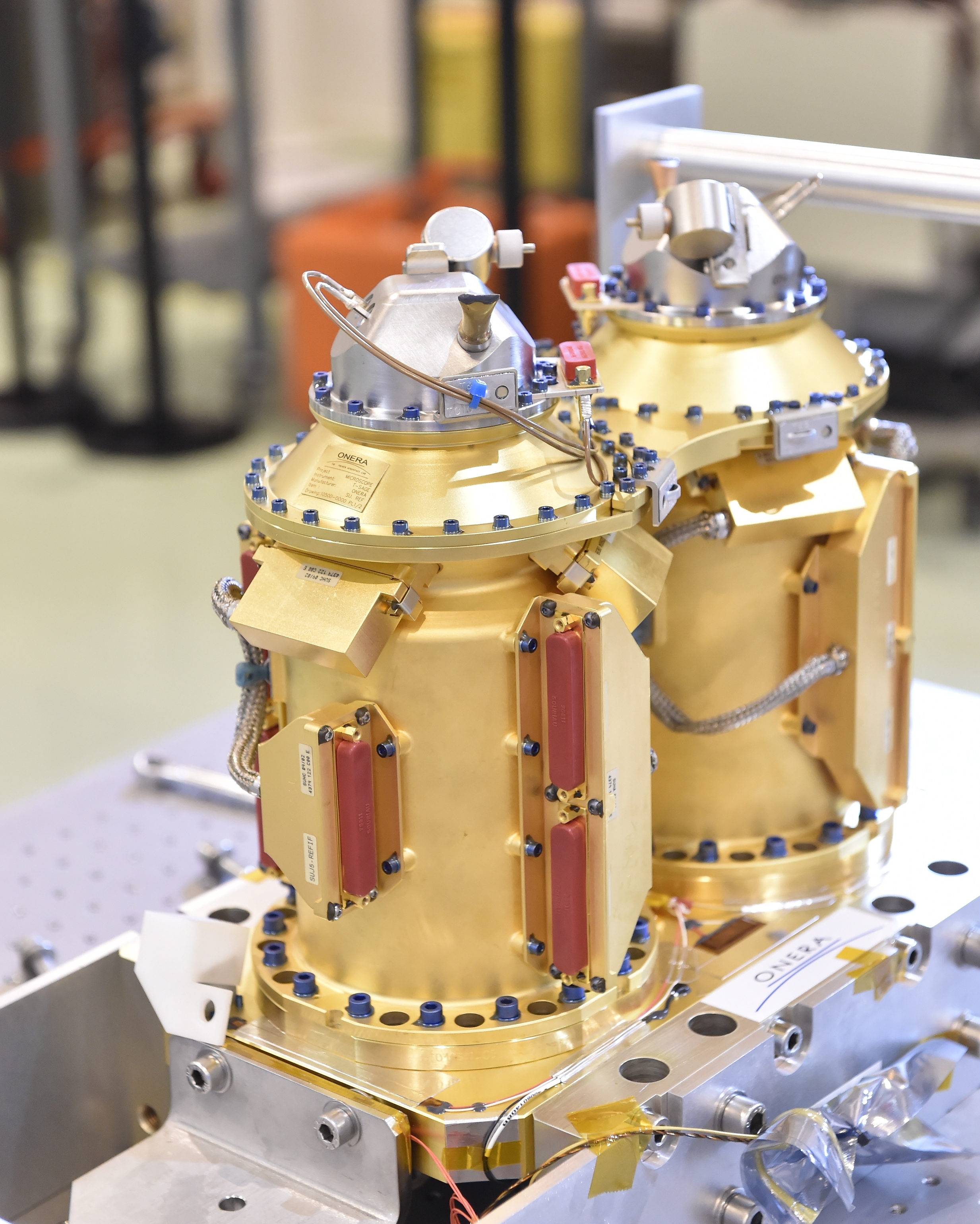
T-SAGE – Twin-Space Accelerometer for Gravity Experiment
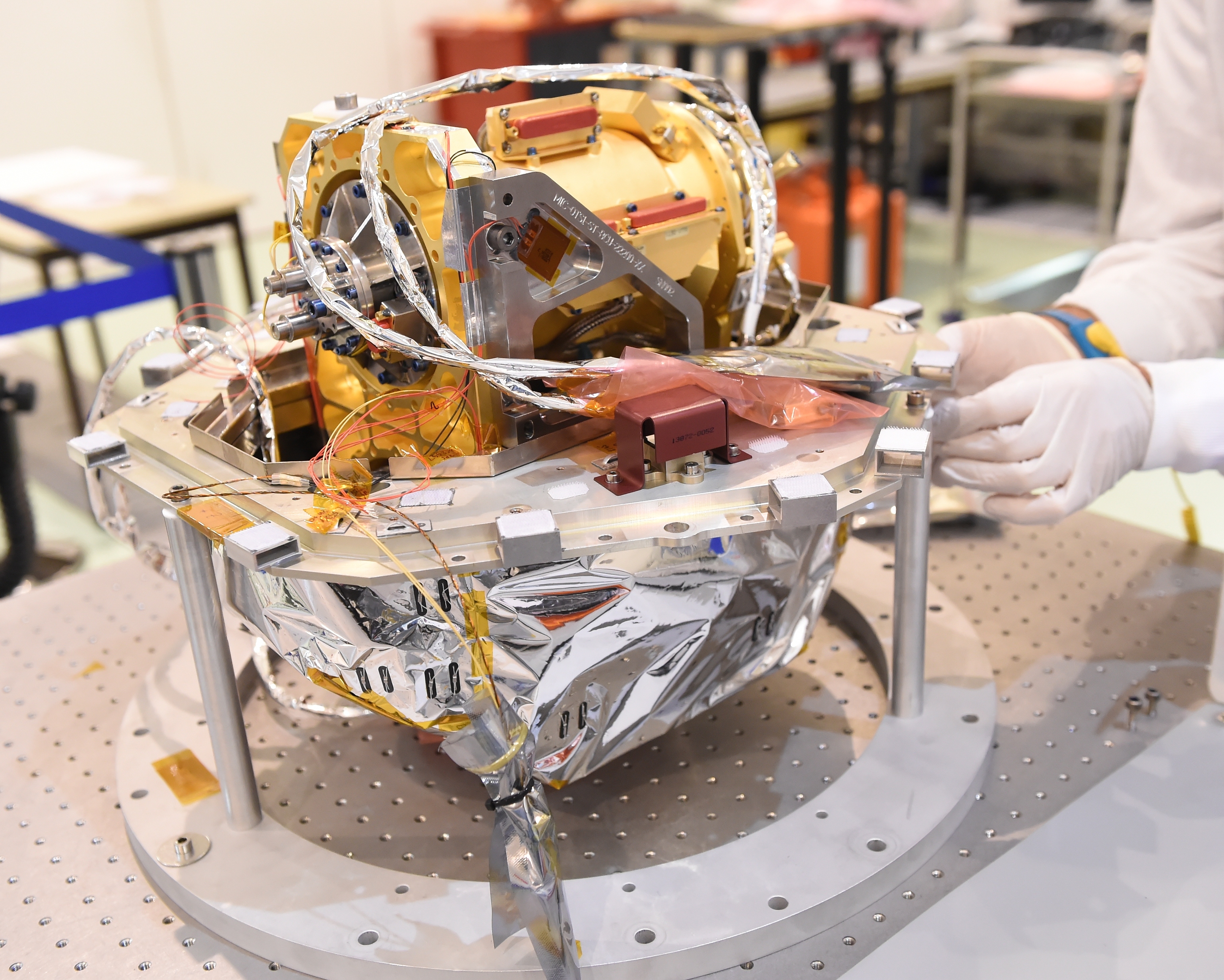
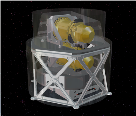
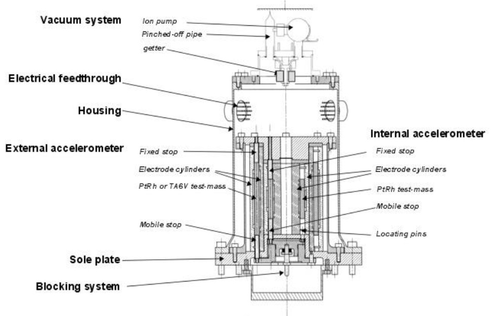
SAGE is the primary payload of the MicroSCOPE spacecraft comprised of a set of two cylindrical concentric electrostatic differential accelerometers. The two SAGE units on the spacecraft are referred to as SAGE-EP (Equivalence Principle) and SAGE-REF (Reference) and a collectively referred to as T-SAGE.
The fundamental principle of an electrostatic accelerometer calls for a proof mass to be suspended in a highly stable electrode cage and measure the electrostatic forces needed to maintain the position of the mass within the case. The measurement is accomplished with capacitive sensors within the cage wall, providing data on the mass position and orientation. In mission mode, the satellite’s Drag Reduction System is operated so that the cage follows the free fall motion of the two masses. The difference in electrostatic forces is then observed to detect any EP-violating signatures.
For SAGE, two inertial sensors are positioned to give their proof masses the same center of gravity to form a single differential accelerometer. The masses are cylindrical with one mass located around an inner mass, both with a common center of mass and the two are machined to have spherical moments of inertia and to reduce gravity gradient disturbances.
Assuming a perfect instrument design, a detection of a difference in acceleration of the two concentric test masses in a perfect Earth geodetic environment would be proof of a violation of the Equivalence Principle. However, machining accuracy has to be considered with regard to miscentering of the masses when looking at the precision of the instrument.
The two SAGE accelerometers on the MicroSCOPE satellite are identical except for the material of their masses. The SAGE-REF accelerometer used for science baseline measurements has two identical masses consisting of platinum-rhodium; SAGE-EP has the external mass in titanium and the inner mass in platinum-rhodium. The Ti mass has a length of 79.9 mm and an outer radius of 35 mm with a mass of 364 grams while the smaller Pt mass is 43.51mm in length with a 20mm outer radius and a mass of 473 grams.
Each mass is maintained in a centered position within the six-degree-of-freedom scheme using electrostatic forces from the surrounding cage comprised of gold-coated silica electrodes. Each mass is connected to a gold wire supplying a high frequency voltage for the capacitive sensing and also keeping the electrical charge of the mass stable. Position signals are sampled at a frequency of 100kHz for science measurements.
The two SAGE sensor units are facilitated within vacuum enclosures to minimize outgassing effects on the instrument.
Each of the sensor units is connected of a Front End Electronics Unit which contains the analog electronics required for proof mass position control, Analog to Digital Converters, Digital Analog Converters and position sensors. Within the FEEU, capacitive sensing of the mass position is completed, and the voltages for the electrodes is generated.
A single Interface Control Unit contains the remaining electronics in charge of controlling the sensor units, specifically the proof mass position control loop and the data/electrical interfaces with the satellite platform. The ICU includes two stacked ICU cards for each FEEU and a common Digital Signals Processor and two Field Programmable Gate Arrays executing the test mass control laws and data processing for the onboard computer. A pair of Power Control Units accept the 28-Volt satellite power bus and convert power to the required voltages for distribution to all SAGE instrument systems.
Both differential accelerometer cores are integrated in tight vacuum enclosures with thermal insulation and magnetic shielding. The typical thermal variation over the course of an orbit is under 0.1°C.
The 50-Kilogram instrument assembly is positioned at the satellite center of mass to reduce any torque demand onto the micro-Propulsion system. In nominal mission operations, the sensitive axis of the accelerometers is oriented in the orbital plane of the spacecraft x-axis with the center of the masses aligned with the rotating axis of the spacecraft, normal to the orbit plane.
Drag Free Attitude Control System
The MicroSCOPE mission must operate its accelerometer payload in a near-perfect environment with no non-gravitational influences, requiring a system to counter drag in the uppermost atmosphere. Initially, the spacecraft was designed to use the Field Emission Electric Propulsion System which was replaced in 2009 with a Cold Gas Propulsion System largely based on the Micro Propulsion System of the Gaia spacecraft.
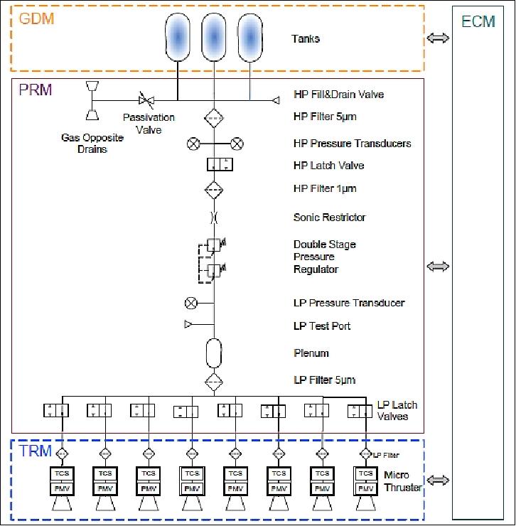
The Cold Gas Propulsion System (CGPS) consists of two identical and fully independent subsystems facilitated on the -Z and +Z panels of the MicroSCOPE Spacecraft. Each of the two strings is comprised of a Gas Distribution Module that stores the propellant gas, a Pressure Regulation Module that distributes the gas to the thrusters at the correct regulated pressures, a Thrust Regulation Module that contains four primary and four redundant Micro Thrusters, and an Electronics Control Module facilitating the power supply, command systems and spacecraft interfaces needed for commanding of the thruster system.
Each Gas Distribution Module consists of three carbon-overwrapped pressure vessels each loaded with 8.25 Kilograms of Nitrogen, pressurized to 345 bar. The three gas bottles of each string are mounted on the respective lateral satellite panel. The Pressure Regulation Module includes a series of pressure transducers and latch valves as well as filters with pressure regulation accomplished by a Two-Stage Pressure Regulator feeding gas at the correct pressure to a Plenum from where it is routed to the thrusters.
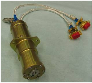
Each line feeding one thruster assembly includes Low-Pressure Latch valves for thruster isolation as well as filters sitting at the thruster inlets. Eight thrusters are part of each CGPS string with four in use as primary while the other four can be used as a redundant system in case any of the primary thrusters fails during the mission.
The thruster system uses high-pressure Nitrogen propellant to provide very small impulses with a thrust range of 1 Micronewton to 500 Micronewtons (0.102 to 51 Milligram-Force) with a thrust resolution better than 2µN and a low response time of 250 milliseconds. Thrust measurement is accomplished with a Miniature Mass Flow Sensor and a piezoelectric actuator is employed for the modulation of the gas flow.
Each of the thrusters is operated at a low inlet pressure of 1 to 2 bar with a tolerance of up to 4 bar. The Micro Thrusters operate at an N2 mass flow of 0.002 to 1 Milligram per second. The thrusters tolerate more than 500 million on/off cycles and have a lifetime of 20,000 hours at an operational temperature of –20 to +50°C.
IDEAS – Innovative Deorbiting Aerobrake System
IDEAS is a new deorbiting system that can allow satellites in higher orbits to comply with the Space Debris Code of Conduct rule specifying that the orbital life span for a Low Earth Orbit satellite should be no more than 25 years after the end of its operational life.
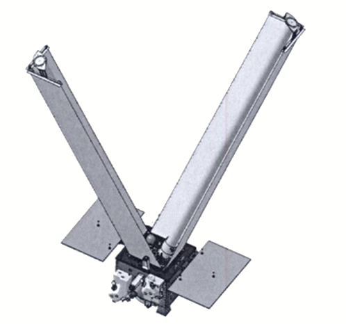
The MicroSCOPE satellite employs a passive deorbiting system based on a pair of sails extended from the satellite body at the end of the mission by two Gossamer arms. This will sufficiently increase the spacecraft’s surface-to-mass ratio allowing atmospheric drag to quickly remove the satellite from orbit. The two arms are inflated with Nitrogen fed from a Titanium vessel.
The two 4.5-Kilogram wings are made of aluminized Kapton forming a membrane structure with a density of 100 grams per square meter. They are deployed from the central inflatable arms using a Tetragonal Accordion Deployment Control System to create a drag surface of 6.3 square maters.
