
CanX-4 & CanX-5
The CanX-4 and 5 satellites (Canadian Advanced Nanospace eXperiment) were developed at the University of Toronto to conduct a demonstration mission dedicated to Satellite Formation Flying using high-accuracy tracking demonstrating algorithms for autonomous formation maintenance in the presence of orbital perturbations with sub-meter accuracy in Earth’s uneven gravitational field.
The CanX program was initiated to allow graduate students gain experience in the development, manufacturing and operation of satellite missions and to test out new, innovative technologies for future application in space missions. CanX-4 and 5 will demonstrate the autonomous and maintenance of a dual-satellite constellation using various geometries, a carrier-differential GPS measurement technique for high-precision relative position determination, and a nanosatellite propulsion system for use to maintain the formation.
The two satellites will perform a one-week formation flying campaign after performing a rendezvous to meet up following the release from the launch vehicle. The operation is limited in time due to the restricted supply of propellant. Once separated, the satellites will demonstrate formation flying at distances of 50 to 1,000 meters using a position control better than one meter and a relative position determination of 10 centimeters.
For the demonstration, the two spacecraft will use GPS information to calculate relative position. An inter-satellite communication system will allow the spacecraft to exchange GPS and attitude data for precise navigation using an accurate attitude control and nanopropulsion system.
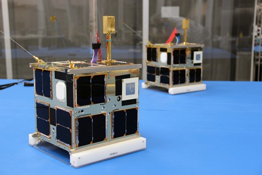
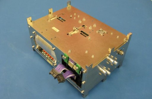
CanX-4 and CanX-5 are identical satellites based on SFL’s Generic Nanosatellite Bus that provides all the required subsystems for the operation of a variety of payloads leaving about 30% of its total volume open for use by payloads. Using the same platform for several previous missions led to a quick build-up of flight heritage and performance data which is of great value when conducting experimental missions.
The satellite bus features a cubical design with a 20-centimeter side length using aluminum exterior panels and two internal trays to host the various satellite subsystems and create a payload bay for simple integration of satellite payloads of different kinds. Each CanX spacecraft weighs around 7 Kilograms.
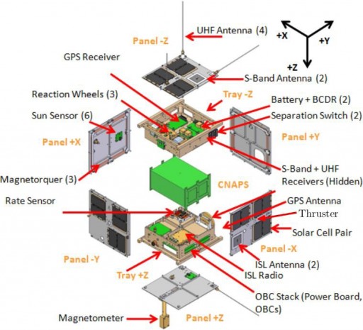
Power is provided by four to ten triple-junction GaAs solar cells installed on each of the external panels delivering up to ten Watts of power using Peak Power Point Tracking provided by the Battery Charge/Discharge Units. Power is stored in two Li-Ion batteries with a capacity of 5.3 Ah. The power conditioning unit provides a 4-Volt unregulated power bus.
Attitude Determination is accomplished by a three-axis magnetometer, six sun sensors for fine and sun attitude determination and a star tracker for precise attitude determination. The Miniature Star Tracker provides three-axis attitude solutions at a control cycle at 0.5 Hz and an accuracy of 10arcsec. Attitude actuation is provided by three reaction wheels with a total mass of 185grams and a volume of 5 by 5 by 4 centimeters. The wheels have a momentum capacity of 30mNms and deliver a maximum torque of 2mNm. Momentum dumps are supported by three magnetotorquers.
Data handling and satellite control is provided by an ARM7 housekeeping computer that handles standard telemetry and communications while a second computer supports all attitude determination and control functions. A third computer board is in charge of the operation of the science payload and handles its data. Each processor board uses the ARM7/TDMI processor with a code memory of 256kB and 2MB of hardware SRAM memory used to store program variables and data. A 256MB flash memory is used for long-term data storage.
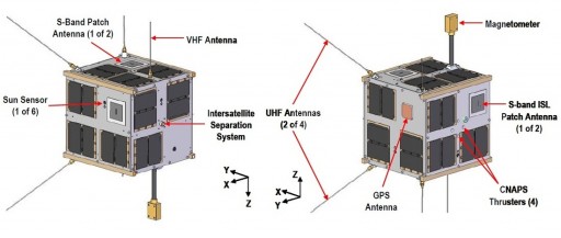
The communications system of the satellites includes a UHF receiver, an S-Band Transceiver and a VHF beacon. The UHF receiver will be used for the command uplink from the ground at a data rate of 4kbit/s in the amateur radio band using quad-canted monopole antennas for omni-directional coverage. The VHF beacon transmits the satellite’s identification and some basic telemetry values for satellite tracking and the initial commissioning of the spacecraft.
The S-Band system is used for data downlink to the ground and the Intersatellite Communication System to allow the exchange of position, velocity and attitude data between the two satellites. The system consists of two patch antennas installed on opposite side panels of the satellites connected to the main S-Band Transceiver. The downlink data rate can be selected between 32 and 256kbit/s while the inter-satellite data rate is about 10kbit/s up to a separation distance of 5 Kilometers.
The two satellites carry identical payloads consisting of CNAPS – the Canadian Nanosatellite Advanced Propulsion System, a GPS receiver and a Formation Flying Control Unit.
The Canadian Nanosatellite Advanced Propulsion System uses heritage components from the NanoPS flown on CanX-2 in 2008. CNAPS will be used to perform precise maneuvers required to maintain a formation in the presence of orbital perturbations.
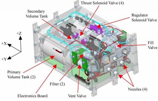
CNAPS is a gas propulsion system using liquid sulfur hexafluorid as a propellant that is ejected through four nozzles that are installed on one external panel of each satellite. The propulsion module measures 18 by 12.5 by 7 centimeters in size featuring two fuel tanks and four nozzles arranged in a cruciform pattern.
Each nozzle achieves a thrust of about 5 Millinewtons and the propulsion system reaches a specific impulse of around 35 seconds. The propellant is stored in a bottle that can hold 300 Milliliters which provides each satellite with a delta-v budget of 14 meters per second which is the limiting factor for the formation demonstration mission.
The four thrusters are pointing to the same direction – the thrust vector is controlled by pointing the satellite into the correct direction for each propulsive maneuver using the reaction wheels and attitude determination system. Each thruster can be controlled independently which is important for long propulsive maneuvers which will require independent control of the thrusters to avoid torques due to thruster misalignment.
A key component of the CanX-4/5 mission is the use of GPS data for absolute and relative navigation. Each satellite is equipped with a dual-band GPS antenna and a dual-band GPS receiver. The antennas are installed on a satellite side panel orthogonal to the thruster panel to be able to point close to zenith during propulsive maneuvers so that the maximum possible GPS satellites are within view.
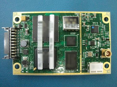
The GPS receiver acquires precise position data for each spacecraft that is immediately transmitted via the Inter Satellite Comm Link for use by the other satellite’s Relative Navigation Software. This software uses the two sets of GPS data to derive a very precise relative position measurement provided the two satellites are using the same GPS satellites which is ensured by both satellites being in an identical orientation at all times with their GPS antennas facing the same direction.
A minimum of four GPS satellites have to be in view to obtain a position fix, but six GPS satellites will significantly improve the accuracy of the navigation data. The navigation system of the satellites can tolerate short GPS blackouts, but will require additional fuel in such a scenario.
The GPS system can achieve an absolute position measurement at an accuracy of <5 meters and the velocity can be detected with <10cm/s accuracy. The relative navigation system using a common GPS set reaches an accuracy of under 5 centimeters in position and under 3 cm/s in velocity allowing extremely precise formation determination and control.
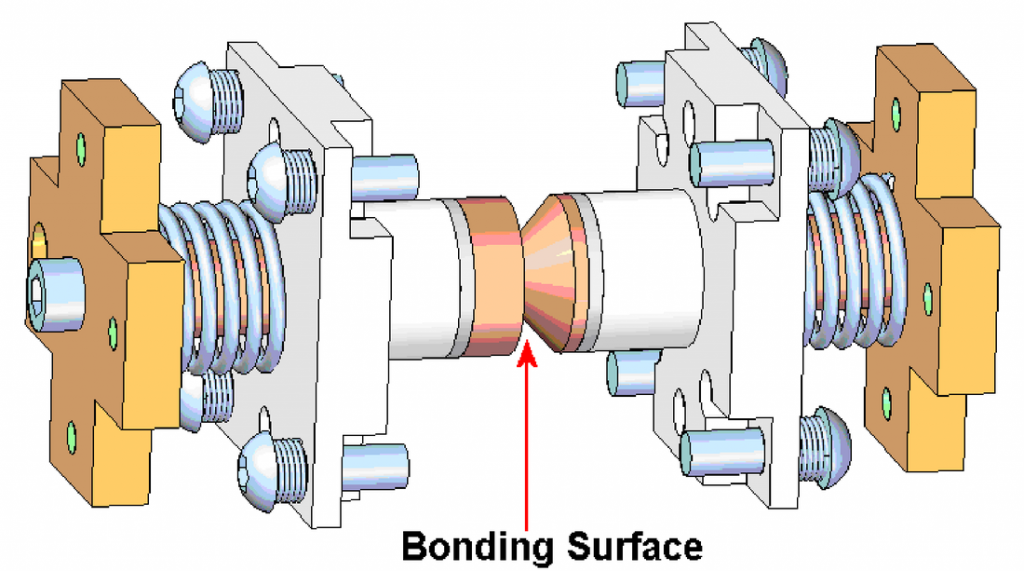
The CanX-4 and 5 satellites were to launch firmly attached to one another using an Intersatellite Separation System for the separation once in orbit and fully commissioned to kick off the formation demonstration. However, the satellites will launch separated from each other and the separation system will not be put to use. The Intersatellite Separation System, ISS for short, consists of two nearly identical interfaces that are installed on the connecting side panels of the two satellites. ISS is comprised of a spring-loaded cone interface that builds the bonding surface between the two spacecraft coated in an electrically debonding agent that acts as a glue holding the satellites together.
For the separation, ISS applies a small voltage to the mechanism which causes the glue to weaken so that the loaded springs can overcome the adhesive force and push the two satellites apart. The two springs are loaded at a force of about 70 Newtons to impart a delta-v of about 8cm/s to each satellite at separation which is reduced to 2.6cm/s in the along-track direction by conducing the separation partially in the orbit-normal direction. This is done to set up the proper conditions for the first formation test.
The formation is controlled by FIONA, the Formation flying Integrated Onboard Nanosatellite Algorithm that uses a pre-programmed definition of each formation experiment to determine the tracking error of the deputy spacecraft and compute the optimal propulsion strategy to correct the error which is then commanded via the spacecraft controller.
Two formation schemes will be tested by the CanX-4 and 5 satellites: Along Track Orbit and Projected Circular Orbit formations. After recovery from the separation event, the two satellites will be assigned their roles – one will be the deputy spacecraft that performs all propulsive maneuvers while the other satellite does not use its propulsion system. Both satellites will exchange attitude data and the passive satellite will mimic the attitude of the deputy spacecraft to ensure both see the same set of GPS satellites for RelNav. The deputy satellite will initially conduct a drift recovery after the separation to get to a defined stationkeeping point for the initiation of the formation maneuvers.
For the Along Track Orbit formation, the two satellites will be in an identical orbit with one satellite flying ahead of the other at a defined separation distance that is maintained by propulsive maneuvers executed by the deputy satellite. The ATO scheme will be demonstrated at distances of 500 and 1,000 meters.
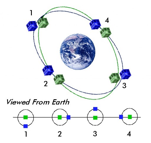
In the Projected Circular Orbit formation mode, the deputy enters an orbit with a slightly different inclination and eccentricity which, when observed from Earth, will seem like the deputy is orbiting the passive satellite. The PCO mode will be demonstrated at distances of 50 and 100 meters.
Each of the formations will be maintained for ten orbits with one orbit of reconfiguration maneuvers in between each formation mode or distance. The criteria for mission success are twofold – first, the level of accuracy to which the satellites can control their relative position in each formation will be assessed, and second, the ability of the deputy satellite to calculate the most efficient maneuvers will be studied to minimize fuel consumption.
Because the two satellites are identical, they can swap roles in the mission. Although the primary mission can be completed with one satellite acting as deputy and expending its fuel, a possible extended mission would be to use the previously passive satellite as deputy to repeat the formation exercise with different parameters. This mission design also adds redundancy in the event of a propulsion system failure on one satellite.
